AXI11154620PORTABLE UHF TRANSCEIVER
Vertex Standard USA, Inc.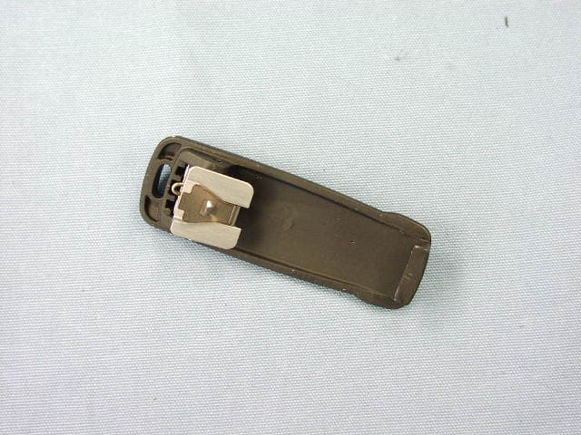
Click to zoom
Application Details
- Equipment Class
- TNF - Licensed Non-Broadcast Transmitter Held to Face
- Date of Grant
- Jul 17, 2013
- Application Purpose
- Original Equipment
- Date of Application
- Jul 16, 2013
- Equipment Note
- PORTABLE UHF TRANSCEIVER
- Frequency Range
- 406.10000000 - 470.00000000
- Company
- Vertex Standard USA, Inc.
- Country
- United States
Documents & Files
Document Text
Text extracted from the exhibit documents filed with the FCC. Open a document above to read the original.
Users Manual
Vertex Standard LMR, Inc. EVX-534 / 539 Operation Guide (Analog Mode / Digital Mode) Switch / Knob Allocation ① Power ON / OFF and Volume Control ・See the LED status shown below. ② CH Selector (Rotary Switch) Channel number is displayed on the LCD. ③ Group Select Switch (Group 1:Analog / Group 2:Digital) The Group changes by pressing this key. When a switch is pushed, "GROUP-01" or "GROUP-02" is displayed. ④ PTT Switch (TX ON / OFF) ・See the LED status shown below. ⑤ Monitor Switch (Manually SQL OFF ) * In Analogue mode only* While receiving, when pressing and holding this key for 2 seconds, the SQL becomes OFF and the radio sounds (output AF). The LED blinks in Green color. When pressing and holding this key again, the sound stops. Note: Press and hold this key when this key needs to be activated. The short press downs not work for this function, though the LED lights in Green. ・See the LED status shown below. ⑥ PN9 Modulation ON/OFF **In Digital mode only** While receiving, when this key is pressed, the radio sounds "pi" and the radio modulates with PN9 in Transmission. When the key is pressed again, the radio sounds "po", and the PN9 modulation is canceled. ・See the LED status shown below. ⑦ LED Status: Power ON:The light blue LED lights once when the radio wakes up. *Analogue mode* RX Monitor (SQL OFF):Green blink *The LED blinks in GREEN, instead of continuous lighting. (No function for the continuous lighting) TX PTT ON :Red (High Power) :Blue (Low Power) **Digital mode** TX PTT ON :Blue (High and Low Power) Vertex Standard LMR, Inc. Switch / Knob Allocation Vertex Standard LMR, Inc.
Users Manual
EVX-534 Operating Manual prOgraMMable FunctiOns/Features IP57 Submersible (1 m/30 min.) 9 Programmable Function Keys 2-Tone Encode/Decode ø 1 5-Tone Encode/Decode ø 1 MDC-1200 ® Encode/Decode ø 1 Scan Group Scan Dual Watch FM-Scan ( Follow-Me Scan ) TA Scan Encryption ø 1 Privacy ø 2 VOX Talk Around Emergency Lone Worker TX Save Disable Direct Channel Entry Code Up/Down ø 1 Code Set ø 1 Speed Dial ø 1 DTMF Code Set ø 1 ID Check ø 1 ARTS TM ø 1 /ARTS II TM ( Auto Range Transpond System ) ø 1: Analog mode only ø 2: Digital mode only EVX-534 A BC D FCC ID: AXI11154620 IC: 10239A-11154620 Introduction...............................................................1 Warning!.FCC.RF.Exposure.Requirements...........2 Before.You.Begin.......................................................4 Battery Pack Installation and Removal ...............4 Battery Charging ..................................................4 Low Battery Indication ........................................5 Belt Clip Installation and Removal .....................6 MIC/SP Cap Installation ......................................6 Controls.&.Connectors.............................................8 LCD.Icons.&.Indicators...........................................9 Operation...................................................................9 Preliminary Steps .................................................9 Operation Quick Start ..........................................9 Automatic Time-Out Timer ...............................12 Advanced.Operation...............................................13 Programmable Key Functions ..........................13 Description of Operating Functions .................16 Lock..........................................................................28 ARTS™/ARTSII™.(Auto.Range.Transpond.System)....28 User.Set.Mode.........................................................29 Optional.Accessories...............................................30 Warranty.Policy......................................................32 cOntents Congratulations! You now have at your fingertips a valuable communications tool, a Vertex Standard two-way radio! Rugged, reliable and easy to use, your Vertex Standard radio will keep you in constant touch with your colleagues for years to come, with negligible maintenance down-time. Please take a few minutes to read this manual carefully. The information presented here will allow you to derive maximum performance from your radio, in case questions arise later on. Important.Note r There are no owner-serviceable parts inside the radio. All service jobs must be referred to an authorized Vertex Standard Service Representative. r In order to maintain the specified water integrity performance, periodic maintenance is recommended. r Should the radio sustain a severe shock (e.g. if it is dropped), the water integrity may be compromised, requiring service. Should this occur, contact your Authorized Vertex Standard Dealer. FCC ID: AXI11154620 IC: 10239A-11154620 EVX-534 OpErating Manual1 Important Notice for North American Users Regarding 406 MHz Guard Band The U.S. Coast Guard and National Oceanographic and Atmospheric Administration have requested the cooperation of the U.S. Federal Communications Commission in preserving the integrity of the protected frequency range 406.0 to 406.1 MHz, which is reserved for use by distress beacons. Do not attempt to pro- gram this apparatus, under any circumstances, for operation in the frequency range 406.0 - 406.1 MHz if the apparatus is to be used in or near North America. Warning - Frequency band 406 - 406.1 MHz is reserved for use ONLY as a distress beacon by the US Coast Guard and NOAA. Under no circumstance should this frequency band be part of the pre programmed oper- ating frequencies of this radio. IntroductIon The EVX-534 is full-featured Hand-Held Digital/Analog Transceiver designed for business communications in the VHF/UHF Land Mobile bands. This transceiver is designed for reliable business communications in a wide variety of applications with a wide range of operating capability provided by their leading-edge design. The EVX-534 allows to 512-channel capacity and 32 groups which can each be programmed with an 8-character Alpha-Numeric Tag. Important channel frequency data is stored in the flash memory on the CPU, and is easily programmable by a Ver- tex Standard licensed dealers using a personal computer with Vertex Standard Programming equipment: FIF-12 USB Programming Interface, and CT-106 Connection cable with CE142 Software. Or, once a single radio is pro- grammed, cloning cable CT-27 can be used to program additional radios directly. The pages which follow will detail the many advanced features provided in the EVX-534 transceiver. After reading this manual, you may wish to consult with your Network Administrator regarding precise details of the configura- tion of this equipment for use in your application. FCC ID: AXI11154620 IC: 10239A-11154620 EVX-534 OpErating Manual2 WarnIng! Fcc rF ExposurE rEquIrEmEnts This Radio has been tested and complies with the Federal Communications Commission (FCC) RF exposure limits for Occupational Use/Controlled exposure environment. In addition, it complies with the following Standards and Guidelines: FCC 96-326, Guidelines for Evaluating the Environmental Effects of Radio-Frequency Radiation. FCC OET Bulletin 65 Edition 97-01 (2001) Supplement C, Evaluating Compliance with FCC Guidelines for Human Exposure to Radio Frequency Electromagnetic Fields. ANSI/IEEE C95.1-1992, IEEE Standard for Safety Levels with Respect to Human Exposure to Radio Frequen- cy Electromagnetic Fields, 3 kHz to 300 GHz. ANSI/IEEE C95.3-1992, IEEE Recommended Practice for the Measurement of Potentially Hazardous Electro- magnetic Fields - RF and Microwave. WARNING: This radio generates RF electromagnetic energy during transmit mode. This radio is designed for and clas- s…
Text truncated - open the document above for the full version.
Users Manual
EVX-539 Operating Manual EVX-539 A B C D 1 4 5 6 7 89 0 # 2 3 ? prOgraMMable FunctiOns/Features IP57 Submersible (1 m/30 min.) 9 Programmable Function Keys 2-Tone Encode/Decode ø 1 5-Tone Encode/Decode ø 1 MDC-1200 ® Encode/Decode ø 1 Scan Group Scan Dual Watch FM-Scan ( Follow-Me Scan ) TA Scan Encryption ø 1 Privacy ø 2 VOX Talk Around Emergency Lone Worker TX Save Disable Direct Channel Entry Code Up/Down ø 1 Code Set ø 1 Speed Dial ø 1 DTMF Code Set ø 1 ID Check ø 1 ARTS TM ø 1 /ARTS II TM ( Auto Range Transpond System ) ø 1: Analog mode only ø 2: Digital mode only FCC ID: AXI11154620 IC: 10239A-11154620 Introduction...............................................................1 Warning!.FCC.RF.Exposure.Requirements...........2 Before.You.Begin.......................................................4 Battery Pack Installation and Removal ...............4 Battery Charging ..................................................4 Low Battery Indication ........................................5 Belt Clip Installation and Removal .....................6 MIC/SP Cap Installation ......................................6 Controls.&.Connectors.............................................8 LCD.Icons.&.Indicators...........................................9 Operation...................................................................9 Preliminary Steps .................................................9 Operation Quick Start ..........................................9 Automatic Time-Out Timer ...............................12 Advanced.Operation...............................................13 Programmable Key Functions ..........................13 Description of Operating Functions .................16 Lock..........................................................................28 ARTS™/ARTSII™.(Auto.Range.Transpond.System)....28 User.Set.Mode.........................................................29 Optional.Accessories...............................................30 Warranty.Policy......................................................32 cOntents Congratulations! You now have at your fingertips a valuable communications tool, a Vertex Standard two-way radio! Rugged, reliable and easy to use, your Vertex Standard radio will keep you in constant touch with your colleagues for years to come, with negligible maintenance down-time. Please take a few minutes to read this manual carefully. The information presented here will allow you to derive maximum performance from your radio, in case questions arise later on. Important.Note r There are no owner-serviceable parts inside the radio. All service jobs must be referred to an authorized Vertex Standard Service Representative. r In order to maintain the specified water integrity performance, periodic maintenance is recommended. r Should the radio sustain a severe shock (e.g. if it is dropped), the water integrity may be compromised, requiring service. Should this occur, contact your Authorized Vertex Standard Dealer. FCC ID: AXI11154620 IC: 10239A-11154620 EVX-539 OpErating Manual1 Important Notice for North American Users Regarding 406 MHz Guard Band The U.S. Coast Guard and National Oceanographic and Atmospheric Administration have requested the cooperation of the U.S. Federal Communications Commission in preserving the integrity of the protected frequency range 406.0 to 406.1 MHz, which is reserved for use by distress beacons. Do not attempt to pro- gram this apparatus, under any circumstances, for operation in the frequency range 406.0 - 406.1 MHz if the apparatus is to be used in or near North America. Warning - Frequency band 406 - 406.1 MHz is reserved for use ONLY as a distress beacon by the US Coast Guard and NOAA. Under no circumstance should this frequency band be part of the pre programmed oper- ating frequencies of this radio. IntroductIon The EVX-539 is full-featured Hand-Held Digital/Analog Transceiver designed for business communications in the VHF/UHF Land Mobile bands. This transceiver is designed for reliable business communications in a wide variety of applications with a wide range of operating capability provided by their leading-edge design. The EVX-539 allows to 512-channel capacity and 32 groups which can each be programmed with an 8-character Alpha-Numeric Tag. Important channel frequency data is stored in the flash memory on the CPU, and is easily programmable by a Ver- tex Standard licensed dealers using a personal computer with Vertex Standard Programming equipment: FIF-12 USB Programming Interface, and CT-106 Connection cable with CE142 Software. Or, once a single radio is pro- grammed, cloning cable CT-27 can be used to program additional radios directly. The pages which follow will detail the many advanced features provided in the EVX-539 transceiver. After reading this manual, you may wish to consult with your Network Administrator regarding precise details of the configura- tion of this equipment for use in your application. FCC ID: AXI11154620 IC: 10239A-11154620 EVX-539 OpErating Manual2 WarnIng! Fcc rF ExposurE rEquIrEmEnts This Radio has been tested and complies with the Federal Communications Commission (FCC) RF exposure limits for Occupational Use/Controlled exposure environment. In addition, it complies with the following Standards and Guidelines: FCC 96-326, Guidelines for Evaluating the Environmental Effects of Radio-Frequency Radiation. FCC OET Bulletin 65 Edition 97-01 (2001) Supplement C, Evaluating Compliance with FCC Guidelines for Human Exposure to Radio Frequency Electromagnetic Fields. ANSI/IEEE C95.1-1992, IEEE Standard for Safety Levels with Respect to Human Exposure to Radio Frequen- cy Electromagnetic Fields, 3 kHz to 300 GHz. ANSI/IEEE C95.3-1992, IEEE Recommended Practice for the Measurement of Potentially Hazardous Electro- magnetic Fields - RF and Microwave. WARNING: This radio generates RF electromagnetic energy during transmit mode. This radio is …
Text truncated - open the document above for the full version.
Cover Letter(s)
June 6, 2013 Timco Engineering, Inc. 849 NW State Roa d 45 P.O. Box 370 Newberry, Flor ida 32669 Subject: AXI11154620 justification letter for ex panded freq uency range 403-470 MHz Gentlemen; You have asked Ver tex Standard for justification to have the 403-470 MHz freq range appear on the face of the FCC Grant of Cer tification for a Part 90 Cer tification. This freq uency range is regarded as usual & customary by United States Federal Gov er nment and its various dep artments, user or ganizations and the military to appear on the face of the eq uipment Grant of Cer tification. (1) Ver tex Standard’s Marketing Dep artment plans to ensure that USA users, ot her than those spec ifically identified in this letter, not op er ate within bands 403-470 MHz, as controlled by the users’ FCC station lic ense. (2) Ver tex Standard understands that is a violation of the FCC rules if the radio is prog rammed to unauthorized freq uencies . (3) Ver tex Standard also understands that the band 406 to 406.1 is res er ved for use by distres s bea cons and as such under no circumstance should this freq uency band be part of the pre prog rammed oper ating freq uencies of this radio. . Sincer ely, Ver tex Standard LMR, Inc. Yukimasa Tomita Exec utive Manager
Cover Letter(s)
May 20, 2013 Federal Communications Commission Authorization and Evaluation Division, 7435 Oakland Mills Road Columbia, MD 21046 USA Re: FCC ID: AXI11154620 EVX-534-G6-5 / EVX-539-G6-5 Gentlemen: Part 15.19 Compliance Statement is placed on the rear of case. Sincerely, Vertex Standard LMR, Inc. Yukimasa Tomita Executive Manager
Cover Letter(s)
May 20, 2013 Federal Communications Commission Authorization and Evaluation Division, 7435 Oakland Mills Road Columbia, MD 21046 USA Re: FCC ID: AXI11154620 EVX-534-G6-5 / EVX-539- G6-5 Gentlemen: A. Part 15.21 Compliance Statement Drawing: B. Part 15.21 Compliance Statement Drawing Location: IN OPERATING MANUAL (location on inside last page) Sincerely, Vertex Standard LMR, Inc. Yukimasa Tomita Executive Manager 12mm Part 15.21: Changes or modifications to this device not expressly approved by Vertex Standard could void the user’s authorization to operate this device. 147mm
Cover Letter(s)
May 20, 2013 Federal Communications Commission Authorization and Evaluation Division, 7435 Oakland Mills Road Columbia, MD 21046 USA Re: FCC ID: AXI11154620 EVX-534-G6-5 / EVX-539-G6-5 Gentlemen: The equipment meets the requirements of the FCC Rules, Part 90.203(e) and (g), as applicable. Programming of this product’s transmit frequencies can be performed only by the manufacturer or by service or maintenance personal. The operator cannot be program transmit frequencies using the equipment’s external operation controls. Sincerely, Vertex Standard LMR, Inc. Yukimasa Tomita Executive Manager
Cover Letter(s)
May 20, 2013 Federal Communications Commission EQUIPMENT APPROVAL SERVICES P. O. Box 358315 Pittsburgh, PA 15251-5315 Attention: Authorization and Evaluation Division Reference: FCC ID: AXI11154620 EVX-534-G6-5 / EVX-539-G6-5 Pursuant to Sections 0.457 (d)(1)(ii) and 0.459 of the Commission’s Rules, the Applicant hereby requires confidential treatment of some of the information accompanying this Application, as listed below: ・ Block Diagram ・ Schematics These materials contain trade secrets and proprietary information not customarily released to the public. The public disclosure of these matters might be harmful to the Applicant and provide unjustified benefits to its competitors. The Applicant understands that pursuant to Rule 0.457 (d)(1)(ii), disclosure of the Application and all accompanying documentation will not be made before the date of Grant for this Application. Sincerely, Vertex Standard LMR, Inc. Yukimasa Tomita Executive Manager
External Photos
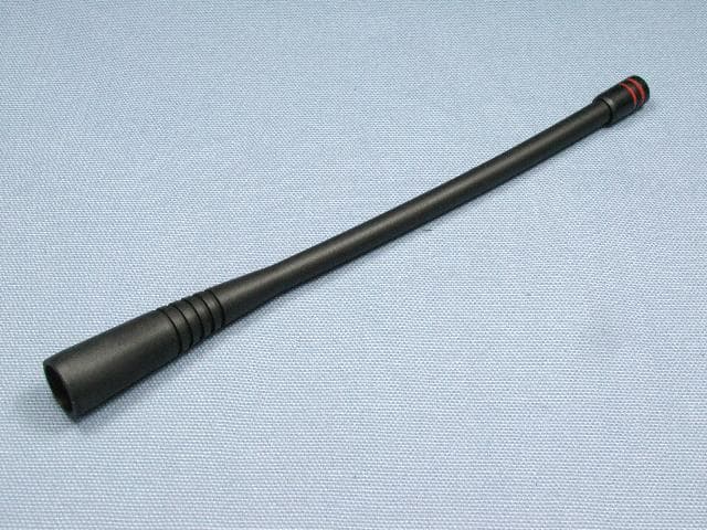
FCC ID:AXI11154620 IC: 10239A-11154620 Vertex Standard LMR, Inc. EVX-534-G6-5 Front view with antenna EVX-539-G6-5 Front view with antenna FCC ID:AXI11154620 IC: 10239A-11154620 Vertex Standard LMR, Inc. EVX-534-G6-5 Front view EVX-539-G6-5 Front view FCC ID:AXI11154620 IC: 10239A-11154620 Vertex Standard LMR, Inc. EVX-534 / 539-G6-5 Rear view EVX-534 / 539-G6-5 Rear view without Battery FCC ID:AXI11154620 IC: 10239A-11154620 Vertex Standard LMR, Inc. EVX-534-G6-5 Right side view EVX-539-G6-5 Right side view FCC ID:AXI11154620 IC: 10239A-11154620 Vertex Standard LMR, Inc. EVX-534-G6-5 Left side view EVX-539-G6-5 Left side view FCC ID:AXI11154620 IC: 10239A-11154620 Vertex Standard LMR, Inc. EVX-534-G6-5 Top View EVX-539-G6-5 Top View FCC ID:AXI11154620 IC: 10239A-11154620 Vertex Standard LMR, Inc. EVX-534-G6-5 Bottom View EVX-539-G6-5 Bottom View FCC ID:AXI11154620 IC: 10239A-11154620 Vertex Standard LMR, Inc. Battery Pack FNB-V133LI (1350mAh) and FNB-V134LI (2250mAh) Battery Charger FCC ID:AXI11154620 IC: 10239A-11154620 Vertex Standard LMR, Inc. AC Adapter Speaker / Microphone MH-45B4B FCC ID:AXI11154620 IC: 10239A-11154620 Vertex Standard LMR, Inc. Speaker / Microphone MH-360S Speaker / Microphone MH-450S FCC ID:AXI11154620 IC: 10239A-11154620 Vertex Standard LMR, Inc. VOX Headset VC-25 Antenna FCC ID:AXI11154620 IC: 10239A-11154620 Vertex Standard LMR, Inc. Belt Clip Installation View of Belt Clip (Bottom)
ID Label/Location Info
EVX-534-G6-5 / EVX-539-G6-5 EVX-534-G6-5 / EVX-539-G6-5 LABEL DRAWINGLABEL DRAWING Vertex Standard LMR, Inc.Vertex Standard LMR, Inc. ID / Part 15.19 and CAUTION drawings ID drawing Part 15.19 and CAUTION drawings Label location EVX-534-G6-5 Model:EVX-534-G6-5 FCC ID: AXI11154620 IC: 10239A-11154620 233G080001 VERTEX STANDARD LMR,INC. MADE IN CHINA SER. NO. 788026138364 2013. 5. 9 2013. 5. 9 EVX-539-G6-5 Model:EVX-539-G6-5 FCC ID: AXI11154620 IC: 10239A-11154620 233G080011 VERTEX STANDARD LMR,INC. MADE IN CHINA SER. NO. 788026138388
Internal Photos
FCC ID:AXI11154620 IC: 10239A-11154620 Vertex Standard LMR, Inc. Side A of MAIN-UNIT With VCO Case (EVX-534 / EVX-539) Side A of MAIN-UNIT Without VCO Case (EVX-534 / EVX-539) FCC ID:AXI11154620 IC: 10239A-11154620 Vertex Standard LMR, Inc. Side B of MAIN-UNIT With Shield Case (EVX-534 / EVX-539) Side B of MAIN-UNIT Without Shield Case (EVX-534 / EVX-539) FCC ID:AXI11154620 IC: 10239A-11154620 Vertex Standard LMR, Inc. Side A of DISPLAY-UNIT (EVX-534 / EVX-539) Side A of DISPLAY-UNIT Without LCD-UNIT(EVX-534 / EVX-539) FCC ID:AXI11154620 IC: 10239A-11154620 Vertex Standard LMR, Inc. Side B of DISPLAY-UNIT (EVX-534 / EVX-539) Front of LCD-UNIT (EVX-534 / EVX-539) FCC ID:AXI11154620 IC: 10239A-11154620 Vertex Standard LMR, Inc. Back of LCD-UNIT (EVX-534 / EVX-539) Inside of chassis FCC ID:AXI11154620 IC: 10239A-11154620 Vertex Standard LMR, Inc. Outside of chassis Inside of front panel (EVX-534) (EVX-539) FCC ID:AXI11154620 IC: 10239A-11154620 Vertex Standard LMR, Inc. PWB of Battery Charger
Operational Description
FCC ID: AXI11154620 IC: 10239A-11154620 Circuit Description EVX-534/539 (UHF) Circuit Description 1. Receiver System 1-1. Front-end RF amplifier Incoming RF signal from the antenna passes through the Low-pass filter, antenna switching diode D1513, D1514 (both 1SS390), and the RF attenuator Q1508 (SKY12338), and then removed undesired frequencies by the varactor tuned band-pass filter D1515 and D1516 (both 1SV323). The filtered RF signal is amplified by Q1518 (2SC5006) and then passes through another varactor tuned band-pass filter D1520 and D1521 (both 1SV323) to remove the undesired frequencies, and then applied to the 1st mixer Q1523 (3SK293). 1-2. First Mixer The RF signal is mixed with the 1st local signal between 352.15 and 419.15 MHz in the 1st mixer Q1523 (3SK293), to produce 50.85 MHz 1st IF signal. The 1st local signal is generated by the VCO, which consists of Q1506 (2SK508), varactor diodes D1502 (1SV279), D1504 (1SV282), D1507 (1SV279), and D1508 (1SV282). The 1st local signal is supplied to the 1st mixer Q1523 (3SK293) through the buffer amplifier Q1510 (2SC5006) and amplifier Q1524 (2SC5005). 1-3. IF Amplifier & Demodulator The 1st IF signal is applied to the monolithic crystal filter XF1501 to strip away all but the desired signal, and then supplied to the custom IC Q1522 (RFIC) through the buffer amplifier Q1526 (2SC5226). The custom IC Q1522 (RFIC) converts the 1st IF signal into the Base Band signal. The Base Band signal from the custom IC Q1522 (RFIC) is applied to another custom IC Q1306 (OMAP), which is demodulated by the Digital Signal Processor. 1-4. Audio amplifier The demodulated signal from the custom IC Q1306 (OMAP) is applied to another custom IC Q1017 (PMAIC). The custom IC Q1017 (PMAIC) adjusts the audio volume level, and then amplifies Q1003 (TDA2822L) the audio signal up to 700 mW (Internal 16Ω). The BTL output audio signal from the Q1003 (TDA2822L) is applied to the audio speaker.(External: 350mW 4Ω) 2. Transmitter System 2-1. MIC Amplifier and modulator The speech signal from internal microphone MC1001 or external microphone J1003 is supplied to the custom IC Q1017 (PMAIC), which is amplified the speech signal. The amplified speech signal from the custom IC Q1017 (PMAIC) is supplied to another custom IC Q1306 (OMAP), which process the speech signal by the Digital Signal Processor. The processed speech signal from the custom IC Q1306 (OMAP) is supplied to the modulator section of the custom IC Q1522 (RFIC), which modulates the speech signal into the FM or digital signal. 2-2. Drive and Final Amplifier Stages The modulated signal from the custom IC Q1522 (RFIC) is buffered by Q1520 (2SC3356) and amplified by the driver amplifier Q1519 (RQA0004PXDQS), and then is applied to the final amplifier Q1513 (RQA0011DNS), which is amplified up to 5 watts output power. The transmit signal then passes through the antenna switch D1512 (RN124S) and is low pass filtered to suppress away harmonic spurious radiation before delivery to the antenna. Vertex Standard LMR, Inc. FCC ID: AXI11154620 IC: 10239A-11154620 Circuit Description 2-3. Automatic Transmit Power Control The current detector Q1528-1 (AD8566ARM) detects the current of the final amplifier Q1513 (RQA0011DNS) and the driver amplifier Q1519 (RQA0004PXDQS), and converts the current difference to the voltage difference. The output from the current detector Q1528-1 (AD8566ARM) is compared with the reference voltage and amplified by the power control amplifier Q1528-2 (AD8566ARM). The output from the power control amplifier Q1528-2 (AD8566ARM) controls the gate bias of the driver amplifier Q1519 (RQA0004PXDQS) and the final amplifier Q1513 (RQA0011DNS). The reference voltage changes into four values (Transmit Power High and Low) controlled by custom IC Q1522 (RFIC). 3. PLL Frequency Synthesizer The frequency synthesizer consists of VCO, TCXO (X1501), and the custom IC Q1522 (RFIC). The output frequency from TCXO is 19.2 MHz and the tolerance is ±1.5 ppm in the temperature range –22 °F to +140 °F (–30 °C to +60 °C). 3-1. VCO (Voltage Controlled Oscillator) While the radio is receiving, the RX oscillator Q1506 (2SK508) generates a programmed frequency between 352.15 and 419.15 MHz as 1st local signal. While the radio is transmitting, the TX oscillator Q1505 (2SC5006) generates a frequency between 403.00 and 470.00 MHz. The output from oscillator is amplified by buffer amplifier Q1510 (2SC5006) and then is divided, one is fed back to the PLL Circuit in the custom IC Q1522 (RFIC). The other one is supplied to the 1st mixer Q1523 (3SK293) through the buffer amplifier Q1524 (2SC5005) in case of the reception. In the transmission, the output is modulated to the FM (or digital) in the custom IC Q1522 (RFIC), and then supplied to the transmitter section described previously. 3-2. VCV (Varactor Control Voltage) Control The tuning voltage (VCV) of the VCO establishes the lock range of VCO by controlling the cathode of varactor diode (D1502 (1SV279), D1504 (1SV282), D1507 (1SV279), D1508 (1SV282) for receiving, and D1501 (1SV279), D1503 (1SV282), D1505 (1SV279), D1506 (1SV282) for transmitting) from the custom IC Q1522 (RFIC). 3-3. PLL The main constitution product of the PLL is equipped all with in the custom IC Q1522 (RFIC), so that all processing regarding the frequency control is performed in the custom IC Q1522 (RFIC). Vertex Standard LMR, Inc.
Parts List/Tune Up Info
Introduction The EVX-53x series has been aligned at the factory for the specified performance across the entire frequency range spec- ified. Realignment should therefore not be necessary except in the event of a component failure. All component replace- ment and service should be performed only by an authorized Vertex Standard representative, or the warranty policy may be voided. The following procedures cover the sometimes critical and tedious adjustments that are not normally required once the transceiver has left the factory. However, if damage occurs and some parts are replaced, realignment may be required. If a sudden problem occurs during normal operation, it is likely due to component failure; realignment should not be done un- til after the faulty component has been replaced. We recommend that servicing be performed only by autho- rized Vertex Standard service technicians who are experi- enced with the circuitry and fully equipped for repair and alignment. Therefore, if a fault is suspected, contact the deal- er from whom the transceiver was purchased for instructions regarding repair. Authorized Vertex Standard service techni- cians realign all circuits and make complete performance checks to ensure compliance with factory specifications after replacing any faulty components. Those who do undertake any of the following alignments are cautioned to proceed at their own risk. Problems caused by unauthorized attempts at realignment are not covered by the warranty policy. Also, Vertex Standard must reserve the right to change circuits and alignment procedures in the interest of improved perfor- mance, without notifying owners. Under no circumstances should any alignment be attempted unless the normal func- tion and operation of the transceiver are clearly understood, the cause of the malfunction has been clearly pinpointed and any faulty components replaced, and the need for realignment determined to be absolutely necessary. The following test equipment (and thorough familiarity with its correct use) is necessary for complete realignment. Correction of problems caused by misalignment resulting from use of improper test equipment is not covered under the warranty policy. While most steps do not require all of the equipment listed, the inter- actions of some adjustments may require that more complex adjustments be performed afterwards. Do not attempt to per- form only a single step unless it is clearly isolated electrically from all other steps. Have all test equipment ready before beginning, and follow all of the steps in a section in the order presented. Required Test Equipment r Radio Tester with calibrated output level at 600 MHz r In-line Wattmeter with 5% accuracy at 600 MHz r 50-ohm, 10-W RF Dummy Load r Regulated DC Power Supply (standard 7.5 VDC, 3 A) r Frequency Counter: ±0.2 ppm accuracy at 600 MHz r AF Signal Generator r AC Voltmeter r DC Voltmeter r UHF Sampling Coupler r IBM PC/Compatible Computer with Microsoft ® Win- dows ® 2000, XP, Vista, or 7 r Micorosoft ® Net Framework 2.0 or later r Vertex Standard CE142 Alignment Program r Vertex Standard FIF-12 USB Programming Interface and CT-106 PC Programming Cable r Vertex Standard FRB-6 Tuning Interface Box and CT-160 Connection Cable Alignment Preparation & Precautions A 50-Ohm RF Dummy Load and in-line wattmeter must be connected to the main antenna jack in all procedures that call for transmission, except where specified otherwise. Correct alignment is not possible with an antenna. After completing one step, read the following step to deter- mine whether the same test equipment will be required. If not, remove the test equipment (except dummy load and wattme- ter, if connected) before proceeding. Correct alignment requires that the ambient temperature be the same as that of the transceiver and test equipment, and that this temperature be held constant between 20 °C and 30 °C. When the transceiver is brought into the shop from hot or cold air, it should be allowed time to come to room tempera- ture before alignment. Whenever possible, alignments should be made with oscilla- tor shields and circuit boards firmly affixed in place. Also, the test equipment must be thoroughly warmed up before begin- ning. Note: Signal levels in dB referred to…
Text truncated - open the document above for the full version.
Contact Information
Applicant
Arine Lee(Certification Manager)
Test Firm
Timco Engineering, Inc.Bruno Clavier
Technical Specifications
| # | Rule Parts | Frequency Range | Power Output | Emission | Tolerance |
|---|---|---|---|---|---|
| 12 | 90.21 | 406.1 MHz - 470 MHz | 5 W | 7K60FXD | 2.5 ppm |
Other Applications from Vertex Standard USA, Inc.
AXI11284620
Jun 30, 20152-WAY PORTABLE RADIO
Equipment Class
TNF - Licensed Non-Broadcast Transmitter Held to Face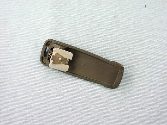
AXI11274620
Jun 30, 20152-WAY PORTABLE RADIO
Equipment Class
TNF - Licensed Non-Broadcast Transmitter Held to Face
AXI11273020
Dec 28, 2014VHF HANDHELD LAND MOBILE RADIO
Equipment Class
TNF - Licensed Non-Broadcast Transmitter Held to Face
AXI11283020
Dec 28, 2014VHF HANDHELD LAND MOBILE RADIO
Equipment Class
TNF - Licensed Non-Broadcast Transmitter Held to Face
AXI11143030
Dec 07, 2014VHF MOBILE TWO-WAY RADIO
Equipment Class
TNB - Licensed Non-Broadcast Station Transmitter