AXYATX034MX-3S Radio Control (R/C) Transmitter
Airtronics Inc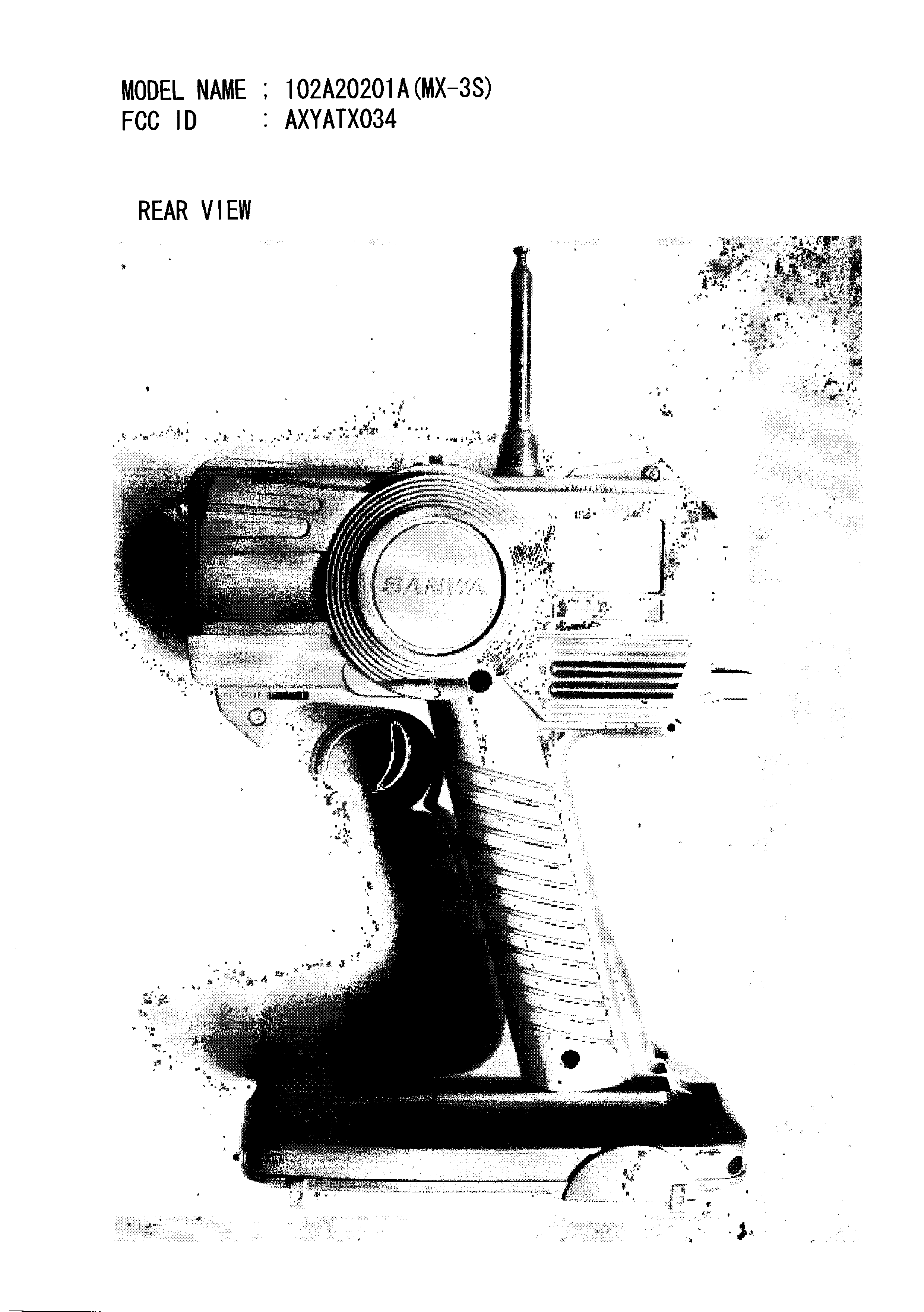
Click to zoom
Application Details
- Equipment Class
- TNB - Licensed Non-Broadcast Station Transmitter
- Date of Grant
- Jun 29, 2004
- Application Purpose
- Original Equipment
- Date of Application
- Apr 22, 2004
- Equipment Note
- MX-3S Radio Control (R/C) Transmitter
- Frequency Range
- 75.41000000 - 75.99000000
- Company
- Airtronics Inc
- Country
- United States
Documents & Files
Document Text
Text extracted from the exhibit documents filed with the FCC. Open a document above to read the original.
Users Manual
3 Channel Computer Radio System M X - 3 S B/ DSC 1 2 3 Synthesized 3 CH. Receiver 92926 75 FM M h z #1#2#3 Steering Throttle AUX B/DSC Switch AA Dry Cell Battery Holder Mechanical Speed Controller #2 Electronic Speed Controller ESC TRANSMITTER BATTERY INSTALLATION RECEIVER AND SERVO CONNECTIONS Your MX-3S Computer R/C system receiver is NOT equipped with BEC circuitry. DO NOT use more than 6.0 volts to power the receiver. Anything higher than 6.0 volts will burn-up or destroy your receiver. Only use a 4.8~6.0 volt battery pack or a speed controller that is designed to lower the voltage to the receiver. The following diagram shows a typical connection for the servos and receiver. Note that the receiver antenna should be located at least 2” (50mm) away from any servo leads and switches. In electric cars, we recommend that it be at least 4” (100mm) from the electric motor. Extend the receiver antenna to the full length. Failure to do so will cause loss of control. Do not cut or bend the receiver antenna. Insulate the connectors with tape or use tie wraps to avoid contact with metal car chassis. Please follow the model manufacturers recommendations for the correct installation of your radio system in your car or boat. Switch To Battery To Motor ! CAUTION When installing your MX-3S radio system in your model, always make sure to set your model on a stand so the wheels are free from any traction before turning on your radio and or connecting your motor for the first time. TRIGGER POSITION ADJUSTMENT Throttle Trigger Set Screw Throttle Trigger Position Gauge A B Throttle Trigger Adjustment screw NOTE: Trigger Set Screw must be loosened before adjusting The Throttle Trigger can be adjusted to give you a more natural feel of the throttle. To Adjust: 1. Loosen the Throttle Trigger set screw by turning counter clock-wise. 2. Turning the adjustment screw clock-wise will move the trigger out or in the (A) direction. 3. Turning the adjustment screw counter clock-wise will move the trigger in or towards the (B) direction. 4. After adjustment is made, re-tighten the Trigger Set Screw. 5. Total adjustment for the trigger is 10mm. Do Not over tighten adjustment screw, it may damage the adjuster and or the threads. TROUBLESHOOTING GUIDE and WARNINGS If your radio system does not operate properly, please check the following items: 1. Make sure the batteries are properly installed and fully charged. Make certain all the batteries are installed in the correct direction. 2. Check that both the transmitter and receiver power switches are in the ON position. 3. Check the battery voltage by turning on the transmitter and pushing both menu bottons at the same time and releasing. 4. Make sure that the proper frequencies are set on both the transmitter and receiver. 5. Make sure all the receiver and servo connections are tight. WARNINGS: DO NOT OPERATE YOUR SYSTEM IF SOMEONE ELSE IS ON YOUR FREQUENCY AT THE SAME TIME. YOUR MODEL CAN CAUSE SERIOUS DAMAGE OR INJURY SO PLEASE USE CAUTION AND COURTESY AT ALL TIMES. DO NOT EXPOSE THE RADIO SYSTEM TO WATER OR EXCESSIVE MOISTURE. PLEASE WATERPROOF THE RECEIVER AND SERVOS BY PLACING THEM IN A WATER TIGHT RADIO BOX WHEN OPERATING R/C BOAT MODELS. IF YOU HAVE LITTLE OR NO EXPERIENCE OPERATING R/C MODELS, WE STRONGLY RECOMMEND YOU SEEK THE ASSISTANCE OF EXPERIENCED MODELERS OR YOUR LOCAL HOBBY SHOP FOR GUIDANCE. To Open slide CoverInstall BatteriesTo Close slide cover Press down on the battery cover and slide in the direction of the arrow to remove. Install 8 pieces “AA” size alkaline batteries as indicated on the battery tray. Make sure to match the polarity (+ and -) as shown in the battery compartment or the transmitter will not function. Install the battery cover in place and slide to close. 1. 2. 3. WARNING: Improper installation of transmitter batteries can cause serious damage to your system. To Battery To Motor ESC REGISTRATION NUMBER The abbreviation, IC, before the registration number signifies that registration was performed based on a Declaration of Conformity indicating that Industry Canada technical specifications were met. It does not imply that Industry Canada approved the equipment. MODEL BATT REV ARC SUB-TMODEL EPAD/R TH H L LR ST MX-3S DIGITAL CONTROL SYSTEM + - INC / DEC MENU MHz 79 75.770 SETUP Synthesized RECEIVER CHANNEL SELECTION By using the supplied screwdriver, you can set the channel number by turning the channel selector dial or dials, located on the front of the receiver. The 75MHz receiver has two dials. The dial on the left can be set from 6~9 and the right dial can be set from 0~9. For example, you what to set your receiver on channel 73. You first set the left dial to the number 7 and the right dial to the number 3. When using a 27MHz receiver, you can select channels 1~6. Available 75Mhz Channels. 61~90 Available 27MHz Channels. 1~6 NOTE: The receiver power must be turned off first before changing channels. BY SANWA C N L H A N E S E L E C T O R 9 8 7 6 9 8 7 6 0 5 4 3 2 1 B/ DSC 1 2 3 Synthesized 3 CH. Receiver 92926 75 FM M h z BY SANWA C A N L H N E S E L E C T O R 9 8 7 6 9 8 7 6 0 5 4 3 2 1 AIRTRONICS Get The Advantage ® SYSTEM FEATURES MODEL BATT REV ARC SUB-TMODEL EPAD/R TH H L LR ST We appreciate your purchase of this new Airtronics MX-3S Synthesized Radio Control System. These instructions are intended to familiarize you with the many unique features of this modern, state of the art equipment. Please read them carefully so you may obtain maximum success and enjoyment from its operation. Please note that the MX-3S is designed for comfort and precise control of all types of model cars and boats. We wish you the best of success with your radio system. Enjoy and have fun. MX-3S Unique and functional pistol grip transmitter design Well balanced for precise control Non-slip foam steering wheel Well placed digital trim levers Optimum third channel switch location Big LCD display Adjustable (70/30) Throttle trigger Low Battery warning Quick …
Text truncated - open the document above for the full version.
ID Label/Location Info
FCC IC Label and Location 1. FCC ID Label FCC ID AXYATX034 2. FCC ID Location
Operational Description
Operational Description The unit under test, Model name MX-3S, is a Frequency Modulated Radio Control (R/C) transmitter. The MX-3S transmitter is used for remote control of ground (e.g. model car, boat) radio control units. The power source of the MX-3S transmitter is a 10VDC Nickel Cadmium battery. The technical specifications for the transmitter are shown below: Transmit frequency range: 75.410MHz ~ 75.990MHz (29 Channels) Modulation type: PPM / FM Transmitter Power Output: 320mW Current Drain: 180mA Power Source: Nickel Cadmium 10VDC battery
Contact Information
Applicant
Ronald Koberg(President)
Technical Contact
Garwood Laboratories, Inc.Arnie Tapia
949-361-9189
950 Calle Negocio · San Clemente, California · United States
Non-Technical Contact
Garwood Laboratories, Inc.Arnie Tapia
[email protected]949-361-9189
Test Firm
Kansai Electronic Industry Dev. Ct.Seiichi Izumi
Technical Specifications
| # | Rule Parts | Frequency Range | Power Output | Emission | Tolerance |
|---|---|---|---|---|---|
| 1 | 95C | 75.41 MHz - 75.99 MHz | 63.10 mW | 4K00F1D | 0.0020000000 % |
Other Applications from Airtronics Inc
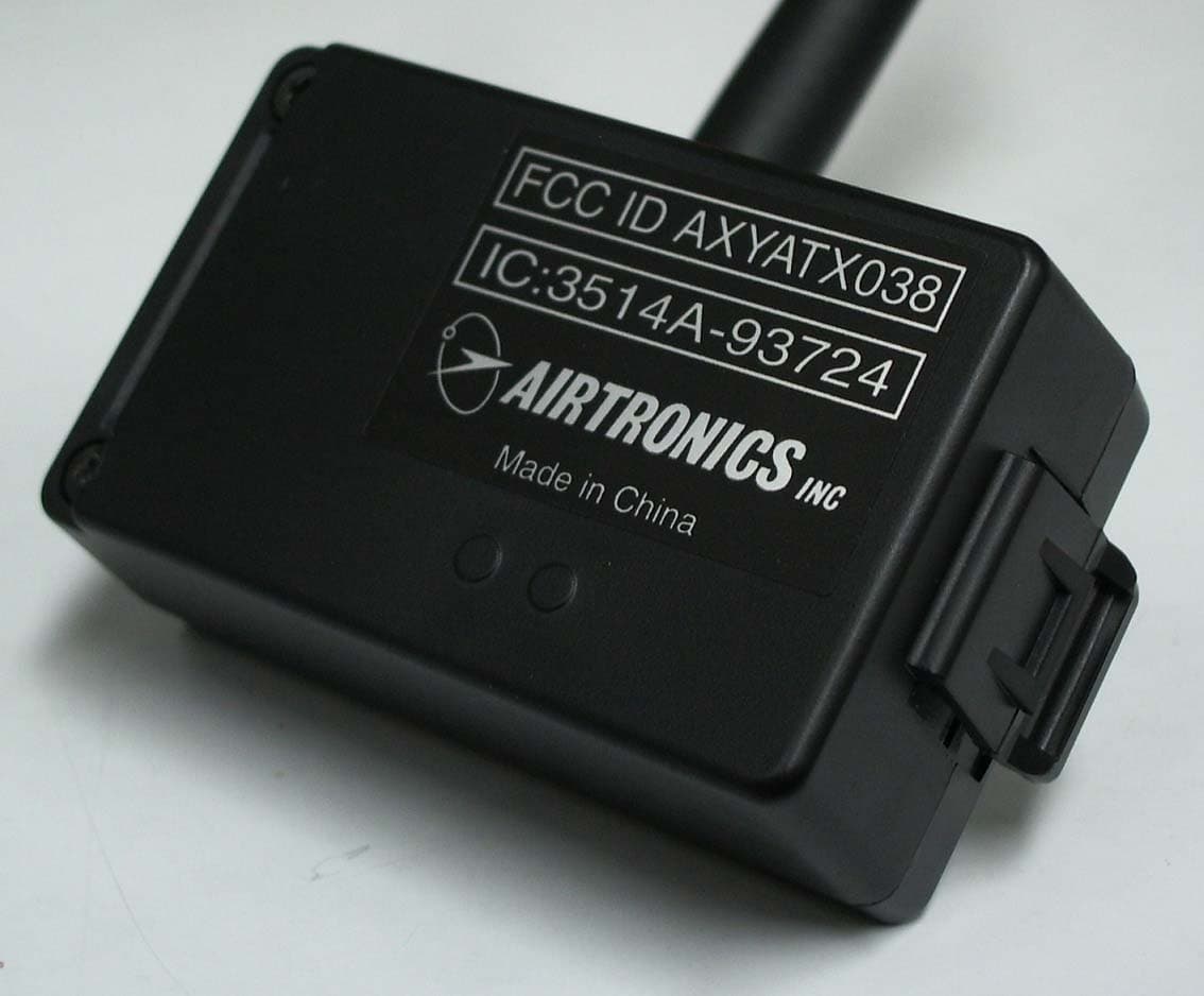
AXYATX038
May 24, 2007Radio controller module for RC Models
Equipment Class
DTS - Digital Transmission System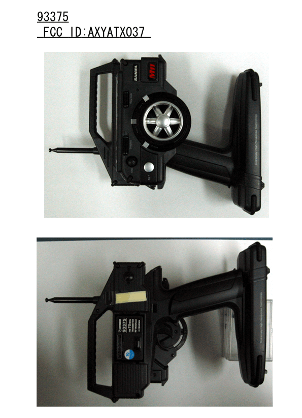
AXYATX037
May 24, 2005Transmitter and Module for Radio Control
Equipment Class
TNB - Licensed Non-Broadcast Station Transmitter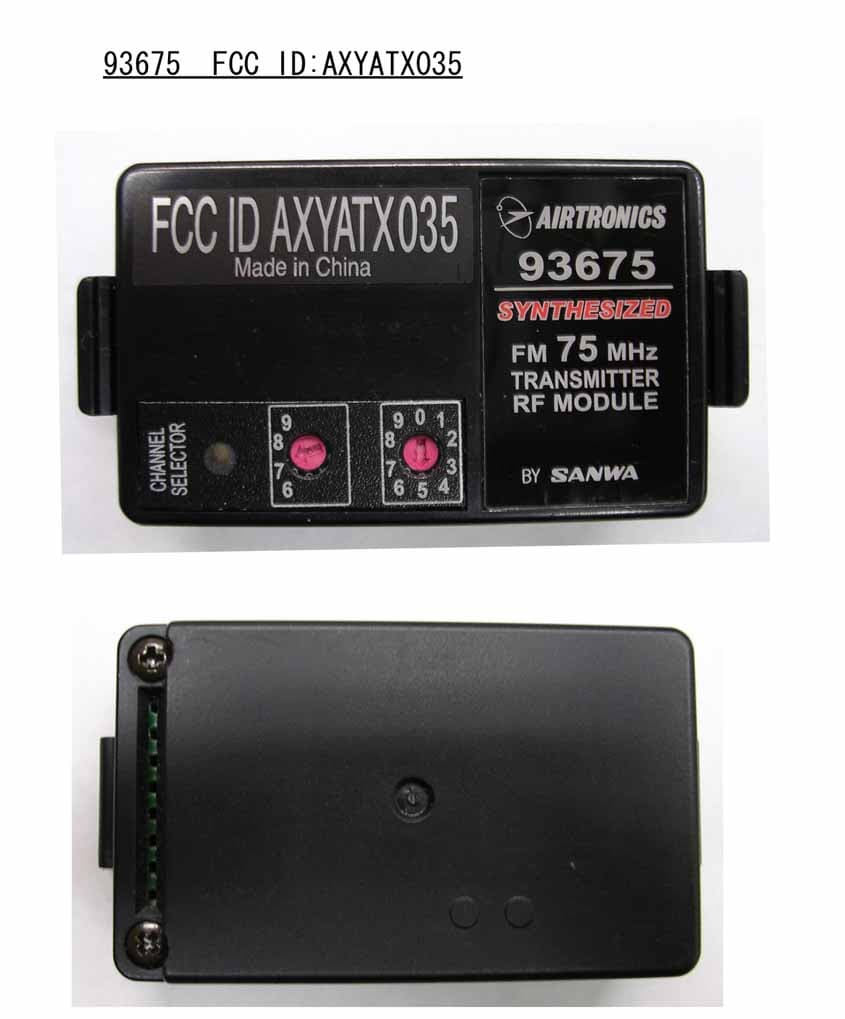
AXYATX035
Jun 06, 2004M8 75MHz Synthesized Module
Equipment Class
TNB - Licensed Non-Broadcast Station Transmitter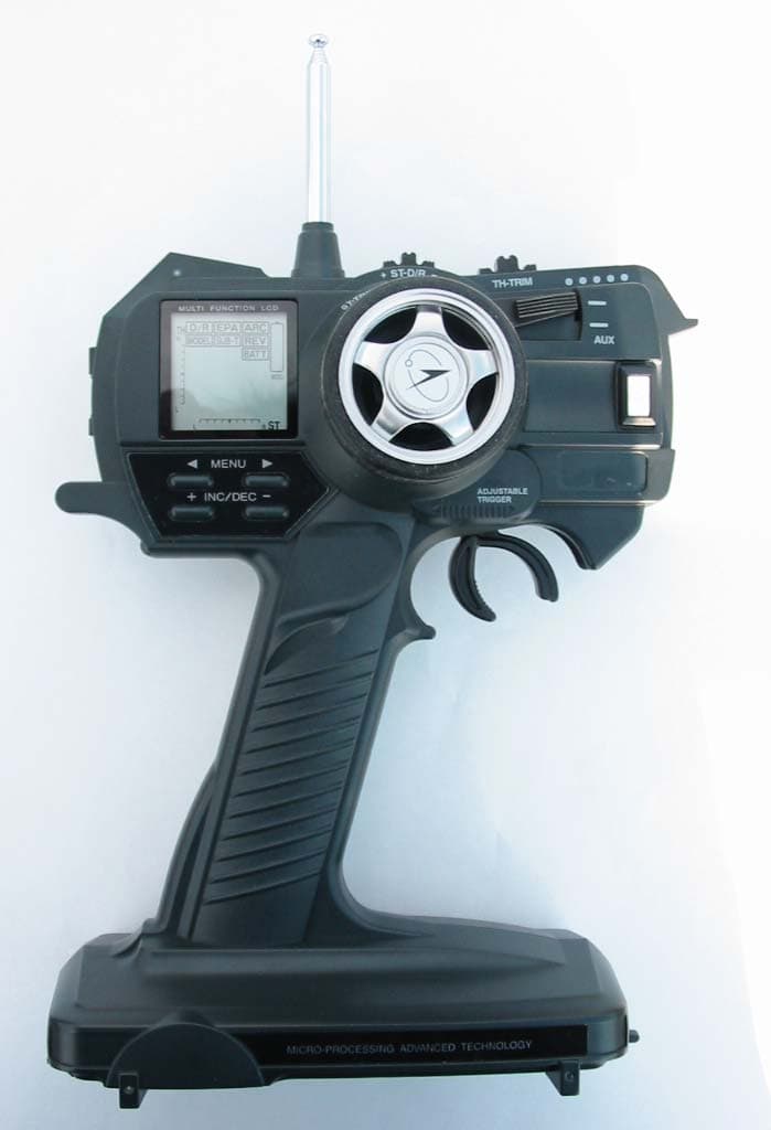
AXYATX036
Jun 03, 2004MX-A Radio Control (R/C) Transmitter
Equipment Class
TNB - Licensed Non-Broadcast Station Transmitter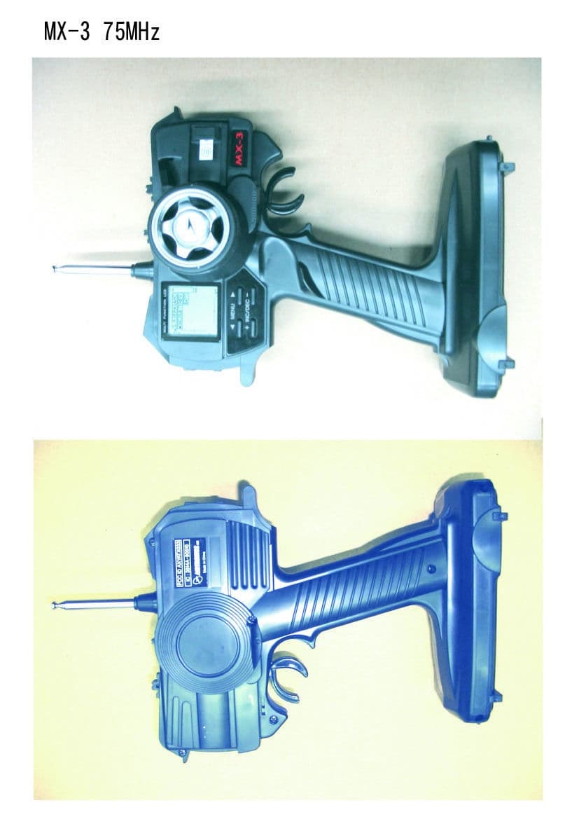
AXYATX033
Jul 31, 2002MX-3 Radio Control System
Equipment Class
TNB - Licensed Non-Broadcast Station Transmitter