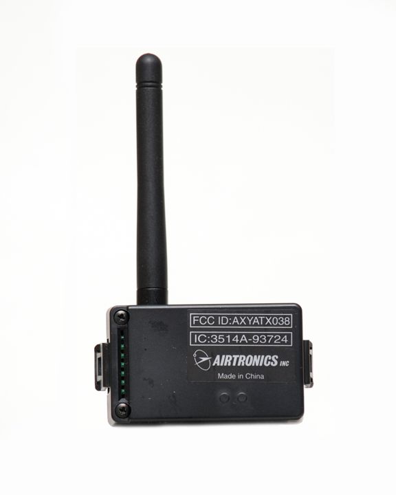
AXYATX038Radio controller module for RC Models
Airtronics Inc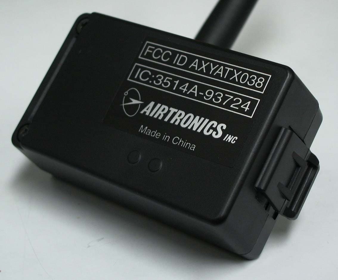
Click to zoom
Application Details
- Equipment Class
- DTS - Digital Transmission System
- Date of Grant
- May 24, 2007
- Application Purpose
- Original Equipment
- Date of Application
- May 09, 2007
- Equipment Note
- Radio controller module for RC Models
- Frequency Range
- 2402.00000000 - 2478.00000000
- Company
- Airtronics Inc
- Country
- United States
Documents & Files
Document Text
Text extracted from the exhibit documents filed with the FCC. Open a document above to read the original.
Users Manual
DSS Module and Receiver Manual 2.4 G H z AIRTRONICS Get The Advantage ® Airtronics Inc 1185 Stanford Court Anaheim, CA 92805 PH: 714-978-1895 FAX: 714-978-1540 Web: www.Airtronics.net Contact: [email protected] (ST) Steering Batt Switch AA Dry Cell Battery Holder Mechanical Speed Controller Electronic Speed Controller Setup ESC Switch To Battery To Motor ! CAUTION When installing your DSS in your model, always make sure to set your model on a stand so the wheels are free from any traction before turning on your radio and or connecting your motor for the first time. To Battery To Motor Binding Button and Blue LED After installing the DSS Receiver and Module, you are now ready to Bind them together. Binding is the proses that will match the DSS Receiver to the DSS Module electronically as a match set. You can Bind additional Airtronics DSS Receivers to your DSS Module to operate many other cars, trucks and or boats. Throttle Fail Safe is a feature that will move the throttle servo to a preset position that you set. If no user preset is added, the Fail Safe will set it-self to the neutral throttle position. BINDING: 1. Turn the power switch to the ON position on the Transmitter. The DSS Module LED will turn on after 6 seconds. 2. Depress and hold the DSS Receiver Binding button. 3. Turn the power switch to the ON position on the DSS Receiver and continue holding the Binding button. The DSS Receiver LED will flash slowly. 4. Release the Binding button on the DSS Receiver after 2 seconds. 5. Depress and hold the Binding button on the transmitter until the LED on the DSS Receiver flashes rapidly. 6. Binding is now complete. Both DSS Module and Receiver LED will now stay on. 7. Operate the controls to confirm. Thank you for purchasing your new DSS Module and Receiver. The DSS Module and Receiver are to be used in an Airtronics M8, M11, Super EXZES and Super EXZES Plus. DO NOT try to use the DSS Module or Receiver in any other radio system. Please read this manual completely before installing and or using it. Always keep this manual to use as a reference. Get the Advantage, Get Airtronics. Install your DSS Receiver as far away from any electrical components as possible. Route the antenna threw a plastic tube so that it is in the upright position. With the receiver power switch in the off position, insert the servos and or ESC as shown in the illustration below. (TH) Throttle (AUX1) Auxiliary 1 (AUX2) Auxiliary 2 Input 6.0v Max (TH) Throttle SERVO CONNECTIONS DSS MODULE Before installing your DSS Module, make sure the power switch is in the OFF position. Read the following instructions first before turning the power switch to the ON position on the transmitter. Binding Button and Blue LED The DSS Module antenna can be rotated 270 left or right and has 3 positions up and down. Adjust the DSS Module antenna to your preference. 270 o 0 45 90 BINDING (RECEIVER to TRANSMITTER) THROTTLE FAIL SAFE After binding of the DSS Module and Receiver, you can set the Throttle Fail Safe feature. 1. Turn the power switch to the ON position on the transmitter. Confirm DSS Module LED is on. 2. Turn the power switch to the ON position on the DSS Receiver. Confirm DSS Receiver LED is on. 3. Move controls to confirm connection between transmitter and receiver. 4. Move throttle lever to your desired Fail Safe position and hold. NOTE: If the throttle lever is left in the neutral position, Fail Safe will be set at that position. 5. Depress the binding button on the DSS Receiver for 4 seconds. LED will flash slow. 6. Release the throttle lever after the receiver LED starts to flash rapidly. 7. Confirm that the Throttle Fail Safe is working properly by turning the transmitter power switch OFF. Turn the transmitter power switch back on to confirm full control. BINDING NOTES You must rebind and reset Throttle Fail Safe on the DSS Receiver when: 1. You change your M11 from (2 to 4) or (4 to 2) channels. 2. Install your DSS Module from a M11 to M8 or M8 to M11. o WARRANTY Your Airtronics DSS Module and DSS Receiver are warranted for the period of one year from the original date of purchase. When in need of any warranty request, send the item to the address below with a detailed note stating the problem you are having and with a copy of the original sales receipt. Any modifying or abuse of the product will void any warranty. The DSS Module and DSS Receiver are not waterproof. Water damage is not covered under any warranty. FCC INFORMATION This device complies with part 15 of the FCC rules. Operation is subject to the following two conditions: (1) This device may not cause harmful interference, and (2) This device must accept any interference received, including interference that may cause undesired operation. Caution: Changes or modifications not expressly approved by the party responsible for compliance could void the user's authority to operate the equipment. This product contains a radio transmitter with wireless technology which has been tested and found to be compliant with the applicable regulations governing a radio transmitter in the 2.400GHz to 2.4835GHz frequency range. The associated regulatory agencies of the following countries recognize the noted certifications for this product as authorized for sale and use: USA Denmark Germany Spain Canada France Italy Sweden Belgium Finland Netherlands UK
Cover Letter(s)
Non-Conformities FCC ID: AXYATX038 (CKC CS Ref # E 07-000022-01) The items listed below represent requests for infor mation following review of this application for cer tification under United States (FCC) regulations. . Further question may arise pending review of responses to t hese items. OK # Non-Conformity or Comment Submitted Response Respondent / Date of Response X 1 The test laboratory accreditation NVLAP 200207- 0 covers testing under FCC part 15B, but does not cover Part 15.247 (ie, part 15C). CKC CS is required by our accreditation requirements (ISO GUIDE 65), b y the FCC and by Industry Canada to ensure that the test laboratory is competent to perform measurements to the listed standards. Listed on KE C Scope is the following: [12/FCC15b] ANSI C63.4 (2003) with FCC Method 47 CF R Part 15, Subpart B Unintentional Radiators One method is to be accredited for the appropriate test specifications (such as part 15C), another method is to undergo a CKC CS re view of competency for the requested scope. In the past, we have accepted the NVLAP scope of accreditation because the devices we certified are receivers tested under part 15B. However, for this application the measurement procedures differ significantly from "normal" part 15B testing. In o rder to avoid requiring KEC to undergo an accreditation scope change, CKC C S can review KEC for competency to perform measurements under 15.247 (an d RSS-210 Annex8). In order to accomplish this task, we need to obtain at least some of the following documentation: - Calibration Reports - Engineer's Training Records - Documentation of test procedures - Quality system procedures for testing - Any documentation which would demonstrate compete nce to perform testing under 15.247 / RSS-210 Annex 8. Note: CKC CS will use the provided test report as p art of the documentation. Commentary: If KEC has other accreditations to ISO 17025 under other accreditation agencies, please forward copies of th is information. Information provided. Airtronics, 5/22/07 X 2 Please provide an operational description in ac cordance with 2.1033, a brief description of the circuit functions of the device along with a statement Operational description provided. Airtronics, 5/22/ 07 describing how the device operates, is modulated an d meets the requirements? This should include a description of the ground system and antenna (if any). It must describe the EUT complete ly in both general and specific terms X 3 A request for confidentiality was not received. This item is to inform the applicant that certain items may be withheld from p ublic inspection in accordance with 47 CFR §0.457 and §0.459. No respo nse necessary for this item. None None x 4 Please provide a users manual in accordance wit h 2.1033. Users manual provided. Airtronics, 5/16/0 7
External Photos
EUT External Photos Figuer 1General Appearance (Front & Side View) Figuer 2General Appearance (Bottom & Side View) Radio Control FCC ID : AXYATX038
Internal Photos
EUT Internal Photos Figure 3 Internal View (Removed Cover) Figure 4 Internal View (Control Board , Front View with Shield) Radio Control FCC ID : AXYATX038 Figure 5 Internal View (Control Board , Front View) Figure 6 Internal View (Control Board , Back View) Radio Control FCC ID.:AXYATX038
Operational Description
Theory of operation4page Theory of operation(RF)21page Cypress Semiconductor Corporation•3901 North First Street•San Jose, CA 95134•408-943-2600 August 19, 2003, rev. 0.B WirelessUSB™ LS Theory of Operation WirelessUSB LS System Overview WirelessUSB LS adds to the existing WirelessUSB portfolio a low-cost 2.4-GHz wireless solution that enables the wireless gaming console peripheral device market and displaces the 27-MHz solutions currently used for low-end retail PC Human Interface Device (HID) applications. A WirelessUSB LS system typically consists of a WirelessUSB LS Bridge and at least one WirelessUSB LS HID. The host PC is not aware of the wireless connection, since the interface to the host acts like a normal wired USB HID connection. Therefore, there is no special software required on the host PC in order to support WirelessUSB LS. Figure 1 is a block diagram of the WirelessUSB LS radio. Direct Sequence Spread Spectrum WirelessUSB LS utilizes a 2.4-GHz direct sequence spread spectrum (DSSS) radio interface. DSSS generates a redundant bit pattern for each bit to be transmitted. This bit pattern is called a “chip” or a pseudo noise code. Notice in Figure 2 that the pseudo noise code is a binary signal that is produced at a much higher frequency than the data that is to be transmitted. Because it has a higher frequency, it has a large bandwidth that spreads the signal in the frequency domain (i.e., it spreads its spectrum). The nature of this signal makes it appear that it is random noise. Note: 1.Figure 2 shows the concept of PN Codes using 10 chip PN codes for illustration purposes only. The LS uses 32 chip and 64 chip PN Codes. SERDES A SERDES B DSSS Baseband A DSSS Baseband B SPI Synthesizer GFSK Demodulator GFSK Modulator IRQ SS SCK MISO MOSI RESET PD DIO DIOV A L RFOUT RFIN X13IN X13 X13OUT Block Dia gram CY WUSB6934 Only Figure 1. WirelessUSB LS Block Diagram "one" data bit "zero" data bit 10-chip code word for each "one" data bit same chip code word but inverted for "zero" data bit Figure 2. Pseudo Noise Code [1] WirelessUSB™LS Theory of Operation 2 Contrast the spread waveform of a DSSS signal with the narrowband waveform of a traditional radio signal, both repre- sented in Figure 3. The wide bandwidth provided by the pseudo noise code allows the signal power to drop below the noise threshold without losing any information. This allows DSSS signals to operate in noisy environments and reduces the interference caused by traditional narrowband signals. The longer the chip is, the greater the probability that the original data can be recovered, and, of course, the more bandwidth required. See the section below on Gold Codes for more information on the 32-bit and 64-bit pseudo noise codes used in WirelessUSB LS. The receiver uses a locally generated replica pseudo noise code and a receiver correlator to separate only the desired coded information from all possible signals. A correlator can be thought of as a very special matched filter: it responds only to signals that are encoded with a pseudo noise code that matches its own code. Thus a correlator can be “tuned” to different codes simply by changing its local code. This corre- lator does not respond to man-made, natural, or artificial noise or interference. It responds only to signals with identical matched signal characteristics and encoded with the identical pseudo noise code. Even if one or more bits in the chip are damaged during transmission, statistical techniques embedded in the radio can recover the original data without the need for retransmission. Auto Correlation Auto correlation is the correlation of a variable with itself over successive time intervals, in our case the pseudo noise code. Pseudo noise codes should have a high autocorrelation factor so that the receiver’s correlator correctly matches the received pseudo noise code with its own code. For example, if “1010” was used as the pseudo noise code, the following sequence shows that the correlator would match the code in two separate time positions (1010 – 0101 – 1010 – 0101). If “1001” was used instead, the correlator would only match the code in a single time position allowing the correlator to correctly process the incoming data stream (1001 – 0011 – 0110 – 1100). WirelessUSB LS uses pseudo noise codes that have a high auto correlation factor (see section on Gold Codes). Cross Correlation Cross correlation is the statistical correlation between two different signals as a function of relative time between the signals. In other words, cross correlation measures how unique different pseudo noise codes are. If pseudo noise codes are used that have a low cross correlation factor their signals will not interfere with each other. For example, if “1001” and “1100” are used as pseudo noise codes, if “1100” is time shifted it becomes “1001” and can be incorrectly matched to by the correlator looking for “1001” and not “1100.” If “1001” and “1011” are used instead, “1011” will never be incorrectly matched by the correlator looking for “1001” because these two pseudo noise codes never match no matter how they are shifted. WirelessUSB LS uses pseudo noise codes that have a low cross correlation factor (see section on Gold Codes). Gold Codes WirelessUSB LS uses sets of Gold Codes as pseudo noise codes in order to enable multiple devices to simultaneously transmit on the same frequency. Gold Codes exhibit high auto correlation and minimal, well defined, cross correlation levels with all other members of the set. Gold Codes are excellent pseudo noise codes for code division multiple access (CDMA) systems. WirelessUSB LS can use 32-bit or 64-bit Gold Codes. There are pros and cons to each code length. 32 bit Gold Codes allow a data rate of 32-kbps, while 64-bit Gold Codes allow a data rate of 16 kbps. On the other hand, using 64-bit Gold Codes has a greater probability of recovering the data due to the longer chip length. Analysis has shown that in order to avoid more tha…
Text truncated - open the document above for the full version.
Schematics
MODULE-RF-TX PARTS LIST (93724) REF No. SPEC R EF No. SPEC R EF No. SPEC PCB 700A14772A R1 47Ω C1 47μF 16V R2 0Ω C2 0.1μF IC1 CYWUSB6953 R3 0Ω C3 0.1μF IC2 SE2550BL R4 0Ω C4 6TPB100MA IC3 TA48M033F R5 27Ω C5 × R6 200Ω C6 0.1μF CN1 5124-06BHPB R7 200Ω C7 0.1μF CN2 U.FL-R-SMT R8 10KΩ C8 0.1μF ANT SW-Z009-0603-50 R9 × C9 0.1μF R10 0Ω C10 0.1μF SW1 SKQMASE010 H4.3 R11 0Ω(2012) C11 0.1μF LED1 SML312BC4TT86 R12 0Ω(2012) C12 0.1μF R13 10KΩ C13 100pF X1 DSX321G13M30 R14 10KΩ C14 100pF X2 × R15 47Ω C15 0.1μF R16 × C16 100pF C17 0.1μF C18 100pF C19 0.1μF C20 0.1μF C21 100pF C22 100pF C23 × C24 10μF (6.3V/1608) C25 0.1μF C26 ×
Test Report
A-004-07-C Page 1 of 40 FCC ID: AXYATX038 KEC Ikoma Testing Laboratory 12128 Takayama-cho Ikoma-city Nara 630-0101 Japan KANSAI ELECTRONIC INDUSTRY DEVELOPMENT CENTER HEAD OFFICE IKOMA TESTING LABORATORY 6-8-7 NISHITENMA 12128 TAKAYAMA-CHO KITA-KU OSAKA 530-0047 JAPAN IKOMA-CITY NARA 630-0101 JAPAN Corporate Juridical Person TEST REPORT Report No. A-004-07-C Date: 16 March 2007 This test report is to certify that the tested device properly complies with the requirements of: FCC Rules and Regulations Part 15 Subpart C Intentional Radiators All the tests necessary to show compliance to the requirements were performed and these results met the specifications of requirement. The results of this report should not be construed to imply compliance of equipment other than that, which was tested. Unless the laboratory permission, this report should not be copied in part. 1. Applicant Company Name : SANWA ELECTRONIC INSTRUMENT CO., LTD. Mailing Address : 1-2-50 Yoshidahonmachi, higashiosaka, Osaka 578-0982 2. Identification of Tested Device Type of Device : Direct Sequence Spread Spectrum Transmitter Type of Modulation : FHSS DSSS Other method Kind of Equipment Authorization : DoC Certification Verification FCC ID : A X YAT X 0 3 8 Device Name : Module for radio control model Trade Name : Airtronics Model Number : 93724 Serial Number : – Production Pre-production Prototype Date of Manufacture : February 2007 3. Test Items and Procedure 6dB Bandwidth Measurement Peak Output Power Measurement Band Edge RF Conducted Emission Measurement Spurious RF Conducted Emission Measurement Power Density Measurement Radiated Spurious Emission Measurement AC Power Line Conducted Emission Measurement Above all tests were performed under: ANSI C63.4-2003 without deviation, with deviation (details are found inside of this report) 4. Date of Test Receipt of Test Sample : 20 February 2007 Condition of Test Sample : Damage is not found on the set. Damage is found on the set. (Details are described in this report) Test Completed on : 6 March 2007 Seiichi Izumi General Manager / Ikoma Testing Laboratory A-004-07-C Page 2 of 40 FCC ID: AXYATX038 KEC Ikoma Testing Laboratory 12128 Takayama-cho Ikoma-city Nara 630-0101 Japan Table of Contents 0. LABORATORY ACCREDITATION AND MEASUREMENT UNCERTAINTY .............................. 3 0.1. Laboratory Accreditation............................................................................................................................. 3 0.2. Measurement Uncertainty ........................................................................................................................... 3 1. CERTIFICATION OF THE COMPLIANCE......................................................................................... 3 2. GENERAL INFORMATION ................................................................................................................... 4 2.1. Product Description..................................................................................................................................... 4 2.2. Description for Equipment Authorization ................................................................................................... 5 2.3. Test Facility ................................................................................................................................................. 5 3. TESTED SYSTEM .................................................................................................................................... 6 3.1. Test Mode .................................................................................................................................................... 6 3.2. Characterization and condition of EUT System .......................................................................................... 6 3.3. Test Setup Diagram ..................................................................................................................................... 7 3.4. Block Diagram of EUT System................................................................................................................... 9 3.5. List of EUT System ..................................................................................................................................... 9 3.6. List of Cables .............................................................................................................................................. 9 4. 6dB BANDWIDTH MEASUREMENT (§15.247 (a) (2)).......................................................................... 10 4.1. Test Procedure ........................................................................................................................................... 10 4.2. Test Results ............................................................................................................................................... 11 5. PEAK OUTPUT POWER MEASUREMENT (§15.247 (b) (3)).............................................................. 14 5.1. Test Procedure ........................................................................................................................................... 14 5.2. Test Results ............................................................................................................................................... 15 6. BAND EDGE RF CONDUCTED EMISSION MEASUREMENT (§15.247 (c))................................... 18 6.1. Test Procedure ........................................................................................................................................... 18 6.2. Test Results ............................................................................................................................................... 19 7. SPURIOUS RF CONDUCTED EMISSION MEASUREMENT (§15.247 (c))...................................... 21 7.1. Test Procedure ........................................................................…
Text truncated - open the document above for the full version.
Test Setup Photos
A-004-07-C Page 1 of 1 FCC ID: AXYATX038 KEC Ikoma Testing Laboratory 12128 Takayama-cho Ikoma-city Nara 630-0101 Japan 1. APPENDIX Photographs of EUT System Configuration Tested Item ・Radiated Emission measurement Horizontally Place Vertically Place
Contact Information
Applicant
Ronald Koberg(President)
Technical Contact
Airtronics, Inc.Ronald Koberg
[email protected]714-978-1895
1185 Stanford Court · Anaheim · United States
Test Firm
Kansai Electronic Industry Dev. Ct.Seiichi Izumi
Technical Specifications
| # | Rule Parts | Frequency Range | Power Output |
|---|---|---|---|
| 1 | 15C | 2.40 GHz - 2.48 GHz | 17.00 mW |
Other Applications from Airtronics Inc
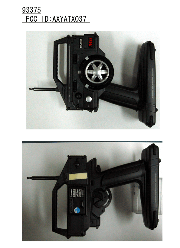
AXYATX037
May 24, 2005Transmitter and Module for Radio Control
Equipment Class
TNB - Licensed Non-Broadcast Station Transmitter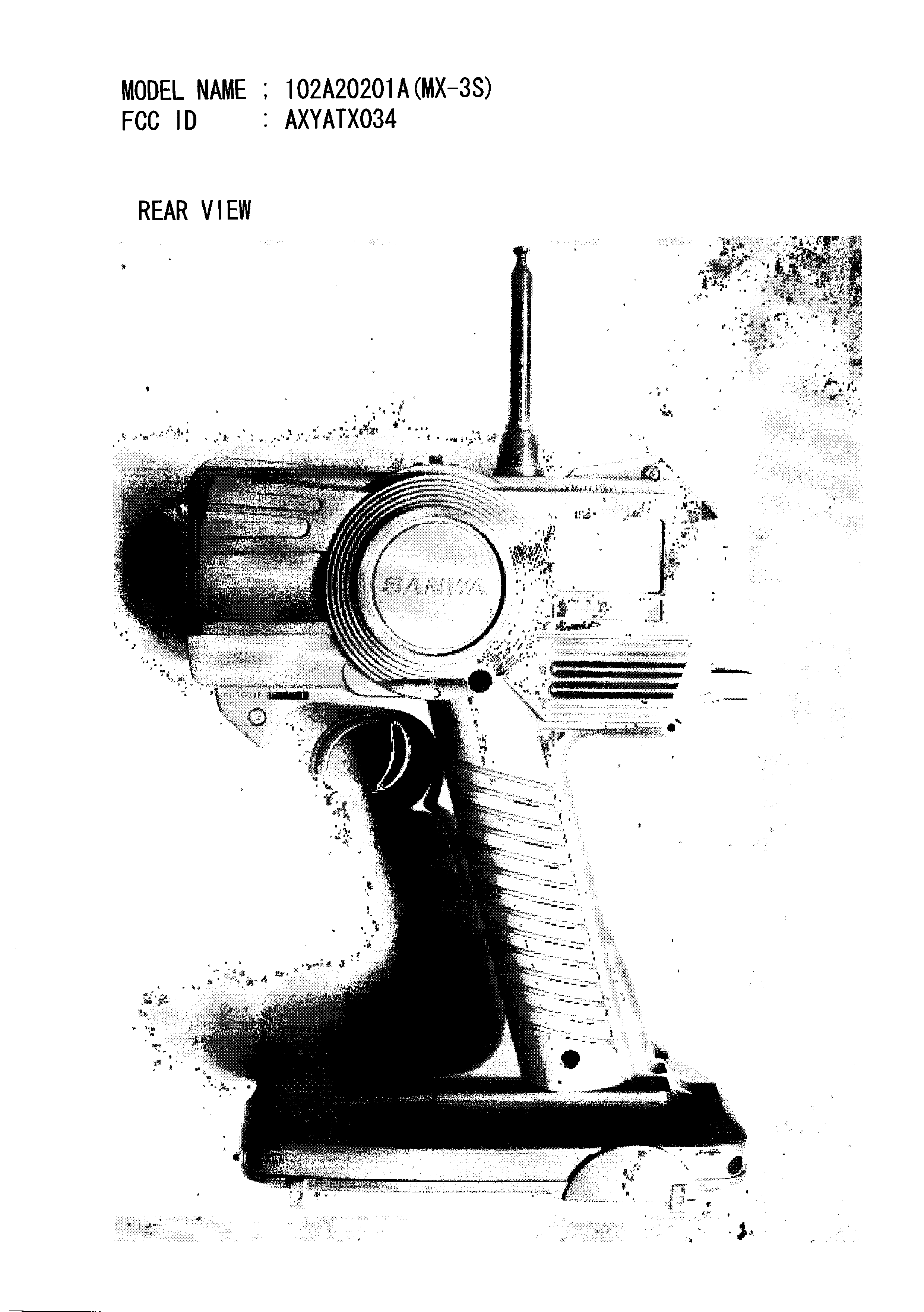
AXYATX034
Jun 29, 2004MX-3S Radio Control (R/C) Transmitter
Equipment Class
TNB - Licensed Non-Broadcast Station Transmitter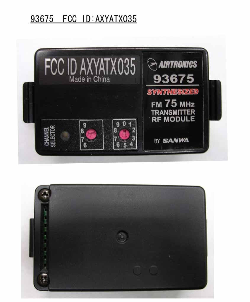
AXYATX035
Jun 06, 2004M8 75MHz Synthesized Module
Equipment Class
TNB - Licensed Non-Broadcast Station Transmitter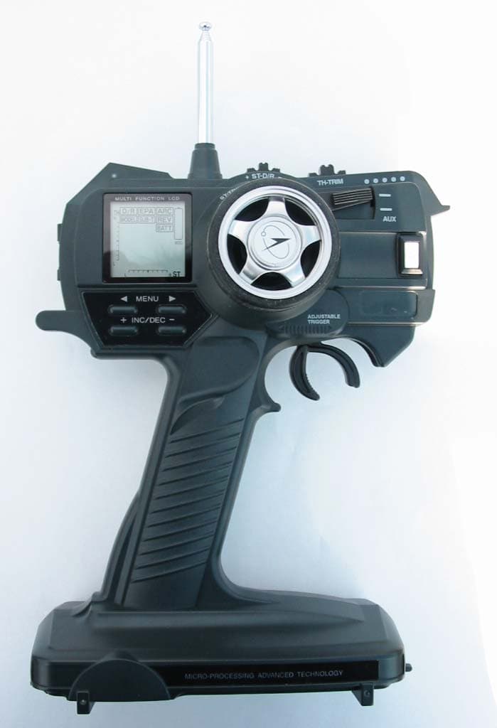
AXYATX036
Jun 03, 2004MX-A Radio Control (R/C) Transmitter
Equipment Class
TNB - Licensed Non-Broadcast Station Transmitter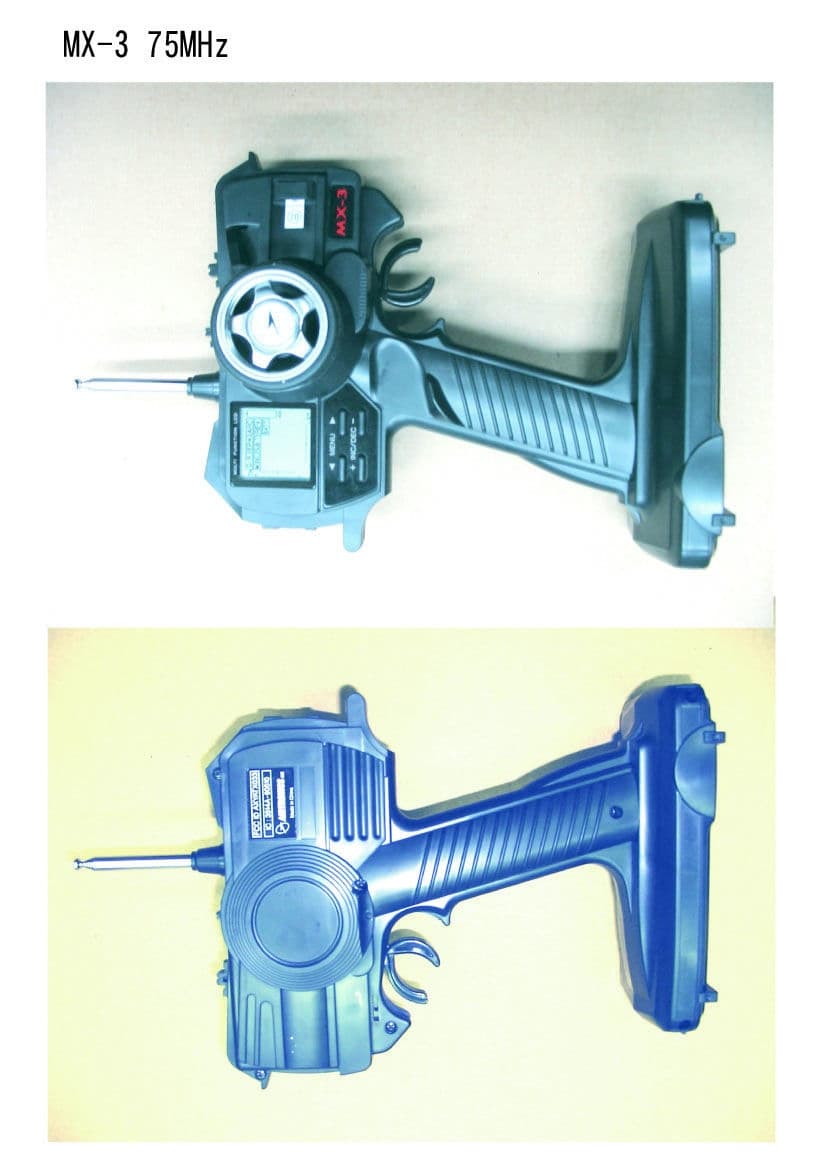
AXYATX033
Jul 31, 2002MX-3 Radio Control System
Equipment Class
TNB - Licensed Non-Broadcast Station Transmitter