AY5SN531PSTH-AModel - SN531 PSTH-A
NEC America Inc
Click to zoom
Application Details
- Equipment Class
- PUE - Part 15 Unlicensed PCS portable Tx held to ear
- Date of Grant
- Jun 29, 2003
- Application Purpose
- Original Equipment
- Date of Application
- Jun 29, 2003
- Equipment Note
- Model - SN531 PSTH-A
- Frequency Range
- 1920.35000000 - 1929.65000000
- Company
- NEC America Inc
- Country
- United States
Documents & Files
Document Text
Text extracted from the exhibit documents filed with the FCC. Open a document above to read the original.
External Photos
COMMUNICATION CERTIFICATION LABORATORY TEST REPORT: 73-7865 FCC ID: AY5SN531PSTH-A Page 4 of 98 Exhibit 3 Exhibit 3: Photographs of Overall Appearance Front View of the SN531 PSTH-A COMMUNICATION CERTIFICATION LABORATORY TEST REPORT: 73-7865 FCC ID: AY5SN531PSTH-A Page 5 of 98 Exhibit 3 Back View of the SN531 PSTH-A COMMUNICATION CERTIFICATION LABORATORY TEST REPORT: 73-7865 FCC ID: AY5SN531PSTH-A Page 6 of 98 Exhibit 3 Outside View of the SN531 PSTH-A Charger
ID Label/Location Info
Remove a battery cover FCC label
Internal Photos
COMMUNICATION CERTIFICATION LABORATORY TEST REPORT: 73-7865 FCC ID: AY5SN531PSTH-A Page 87 of 98 Exhibit 9 Exhibit 9: Internal Photographs Inside View of the SN531 PSTH-A COMMUNICATION CERTIFICATION LABORATORY TEST REPORT: 73-7865 FCC ID: AY5SN531PSTH-A Page 88 of 98 Exhibit 9 Back cover showing the antenna COMMUNICATION CERTIFICATION LABORATORY TEST REPORT: 73-7865 FCC ID: AY5SN531PSTH-A Page 89 of 98 Exhibit 9 Side A of the Digital board COMMUNICATION CERTIFICATION LABORATORY TEST REPORT: 73-7865 FCC ID: AY5SN531PSTH-A Page 90 of 98 Exhibit 9 Side A of the RF board COMMUNICATION CERTIFICATION LABORATORY TEST REPORT: 73-7865 FCC ID: AY5SN531PSTH-A Page 91 of 98 Exhibit 9 Side B of the RF board COMMUNICATION CERTIFICATION LABORATORY TEST REPORT: 73-7865 FCC ID: AY5SN531PSTH-A Page 92 of 98 Exhibit 9 Side B (Keypad and LCD display)
RF Exposure Info
EXHIBIT 11 The SN531 PSTH-A was previously certified under FCC ID # AY5SN531PSTH. A change has been made to the modulator, which requires a new grant of certification under section 2.1043. The new FCC ID # is AY5SN531PSTH-A. It is NEC’s opinion that the change made to the modulator will not effect SAR compliance; therefore, NEC is submitting the original SAR data to show compliance. Please see rational below. - No change has been made to the antenna - No change has been made to the packaging - The conducted power at the antenna terminal is within 0.5 dB of original unit - The original peak 1-g SAR was 0.061 W/kg A 0.5 dB change in conducted power could not possibly cause the peak 1-g SAR to increase from 0.061 W/kg to exceed 1.6 W/kg. Even if the 0.5 dB power increase caused the 1-g SAR to increase by 2,600% it would still be in compliance. Based on the fact that it is unlikely that the minor change in performance (0.5 dB) could cause the 1-g SAR to increase by more than 2,600%, NEC is submitting the original SAR data to show compliance. See original SAR data below.
Test Report
TEST REPORT FROM: COMMUNICATION CERTIFICATION LABORATORY 1940 W. Alexander Street Salt Lake City, Utah 84119-2039 Type of Report: Certification TEST OF: SN531 PSTH-A FCC ID: AY5SN531PSTH-A To Part 15 Subpart D of the FCC Rules and Regulations Test Report Serial No: 73-7865 Applicant: NEC AMERICA, INC. 6535 North State Hwy 161 Irving, TX 75039-2402 Date(s) of Test: April 22 - 28, 2003 Issue Date: May 21, 2003 Equipment Receipt Date: April 22, 2003 COMMUNICATION CERTIFICATION LABORATORY TEST REPORT: 73-7865 FCC ID: AY5SN531PSTH-A Page 1 of 72 CERTIFICATION OF ENGINEERING REPORT This report has been prepared by Communication Certification Laboratory to evaluate the device described below with the requirements of FCC Part 15, Subpart D. Specific identifying information for the device tested is given below. - Applicant NEC AMERICA, INC. 6535 North State Hwy 161 Irving, TX 75039-2402 - Manufacturer: NEC Corporation 7-1 5 Chome Shiba Minato-Ku Tokyo, 108-01 Japan - Trade Name: NEC - Model Number: SN531 PSTH-A - FCC ID Number: AY5SN531PSTH-A On this 21 st day of May 2003, I, individually, and for Communication Certification Laboratory, certify that the statements made in this engineering report are true, complete, and correct to the best of my knowledge, and are made in good faith. COMMUNICATION CERTIFICATION LABORATORY Tested by: Jeffrey L. Draney EMC Technician COMMUNICATION CERTIFICATION LABORATORY TEST REPORT: 73-7865 FCC ID: AY5SN531PSTH-A Page 2 of 72 SECTION 1 GENERAL INFORMATION 1.1 Product Description The SN531 PSTH-A is the handset (PS) portion of a wireless PBX system. The system consists of a PBX, Wireless Communication system (WCS) (installed inside of the PBX), ZT and handset (PS). The ZT’s are installed throughout the coverage area and hard wired to the base station controller. The user carrier a wireless PS which allows the user access to the PBX functions from any location within the coverage area. This application is for the PS which is identified by FCC ID: AY5SN531PSTH-A. The ZT portion of the system is unchanged from the original certification identified by FCC ID: AY5SN933WEK. The ZT (MN:SN933 WEK-A) performs all of the channel monitoring and selection functions. The ZT was not changed, and all of the test data on the ZT was taken from the original certification report. This PS is functionally the same as a previously certified PS (FCC ID: AY5SN531PSTH); therefore, it can be installed with the previously certified PS’s and will also work with the previously certified ZT’s (FCC ID: AY5SN933WEK). 1.2 Test Specification The SN531 PSTH-A is an Isochronous device that operates in the 1920-1930 MHz sub-band; therefore the SN531 PSTH-A is subject to the provisions of FCC Part 15, Subpart D. Unlicensed Personal Communications Service Devices. 1.3 Test Methods & Procedures The SN531 PSTH-A was tested in accordance with ANSI C63.17-1998. COMMUNICATION CERTIFICATION LABORATORY TEST REPORT: 73-7865 FCC ID: AY5SN531PSTH-A Page 3 of 72 SECTION 2. SUMMARY OF TEST RESULTS: 2.1 Summary of Tests: FCC Section Description Report Section ANSI C63.17 Section Result 15.307 Affidavit from UTAM, Inc. certifying participation in UTAM, Inc. 3.2.1 N/A Complies 15.309 Cross Reference to Subpart B 3.2.2 6.1.6.3 Complies 15.311 Labelling Requirements 3.2.3 N/A Complies 15.315 AC power line conducted limits 3.2.4 N/A Complies 15.317 Antenna requirement 3.2.5 N/A Complies 15.319 (a) Frequency of operation 3.2.6 N/A Complies 15.319 (b) Modulation technique 3.2.7 6.1.4 Complies 15.319 (c) Peak transmit power and emission bandwidth 3.2.8 6.1.2 Complies 15.319 (d) Power spectral density 3.2.9 6.1.5 Complies 15.319 (e) Directional gain of antenna 3.2.10 N/A Complies 15.319 (f) Automatic discontinuance of transmission 3.2.11 N/A Complies 15.319 (i) IEEE C95.1-1991 and IEEE C95.3- 1991 3.2.12 N/A Complies COMMUNICATION CERTIFICATION LABORATORY TEST REPORT: 73-7865 FCC ID: AY5SN531PSTH-A Page 4 of 72 FCC Section Description Report Section ANSI C63.17 Section Result 15.323 (a) Channel allocation 3.2.13 N/A Complies 15.323 (b) Channel packing 3.2.14 8.1.2 Complies 15.232 (c) Time and Spectrum monitoring 3.2.15 Sections 7 and 8 Complies 15.323 (c)(1) Transmit window monitoring 3.2.16 7.3.2.2 7.5 Complies 15.323 (c)(2) Monitoring threshold 3.2.17 7.3.2.1 Complies 15.323 (c)(3) Transmission duration 3.2.18 N/A Complies 15.323 (c)(4) Acknowledgments 3.2.19 8.2.1 8.1.3 Complies 15.323 (c)(5) Least interfered channel 3.2.20 7.3.2.1, 7.3.2.2 8.2.1 Complies 15.323 (c)(6) Random waiting interval 3.2.21 8.1.3 8.2.1 Complies 15.323 (c)(7) Threshold monitoring bandwidth, Threshold monitoring reaction time 3.2.22 7.4 7.5 Complies 15.323 (c)(8) Threshold monitoring antenna 3.2.23 N/A Complies 15.323 (c)(9) Monitoring threshold relaxation 3.2.24 N/A Complies 15.323 (c)(10) Duplex connections 3.2.25 8.2.3 Complies 15.323 (c)(11) Alternative monitoring interval 3.2.26 8.2.4 Complies COMMUNICATION CERTIFICATION LABORATORY TEST REPORT: 73-7865 FCC ID: AY5SN531PSTH-A Page 5 of 72 FCC Section Description Report Section ANSI C63.17 Section Result 15.323 (c)(12) Limitation on use of Section (c)(10) or (c)(11) 3.2.27 N/A Complies 15.323 (d) Spurious emissions 3.2.28 6.1.6 Complies 15.323 (e) Frame repetition stability / frame period and jitter 3.2.29 6.2.3 6.2.4 Complies 15.323 (f) Frequency stability 3.2.30 6.2.2 Complies COMMUNICATION CERTIFICATION LABORATORY TEST REPORT: 73-7865 FCC ID: AY5SN531PSTH-A Page 6 of 72 SECTION 3. MEASUREMENTS, EXAMINATIONS AND DERIVED RESULTS: 3.1 General Comments This section contains the test results only. Details of the test methods used, etc., can be found in Appendix A of this report. 3.2 Test Results 3.2.1 Coordination with fixed microwave service § 15.307 Measurement Data: The affidavit from UTAM, Inc. is enclosed in Exhibit 12. 3.2.2 Cross Reference to Subpart B § 15.309 The requirements of Subpart D apply only to the radio transmitter contained in the PCS device. Other aspects of the operation of a …
Text truncated - open the document above for the full version.
Test Setup Photos
COMMUNICATION CERTIFICATION LABORATORY TEST REPORT: 73-7865 FCC ID: AY5SN531PSTH-A Page 84 of 98 Exhibit 7 Exhibit 7: Test Set-Up Photographs Front View of Worst Case Radiated and Line Conducted Emissions Test Set-up COMMUNICATION CERTIFICATION LABORATORY TEST REPORT: 73-7865 FCC ID: AY5SN531PSTH-A Page 85 of 98 Exhibit 7 Back View of Worst Case Radiated and Line Conducted Emissions Test Set-up
Contact Information
Applicant
Peter Bevilacqua(Assistant General Manager Reg. & Quality Mgmnt.)
Technical Contact
Communication Certification LaboratoryKirk P Thomas
[email protected]801-972-6146
1940 West Alexander Street · Salt Lake City, Utah · United States
Test Firm
Communication Certification Lab.Scott Earl
Technical Specifications
| # | Rule Parts | Frequency Range | Power Output | Tolerance |
|---|---|---|---|---|
| 1 | 15D | 1.92 GHz - 1.93 GHz | 35.40 mW | 0.8800000000 ppm |
Other Applications from NEC America Inc
AY5WLPS1EMH210
Aug 02, 2004WLAN IP Phone
Equipment Class
DTS - Digital Transmission System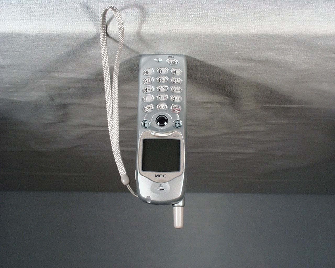
AY5PS3D
May 23, 2004Model PS3D Handset
Equipment Class
PUE - Part 15 Unlicensed PCS portable Tx held to ear
AY5SN992CSEO
Feb 09, 2000Unlicensed PCS Base Station
Equipment Class
PUB - Part 15 Unlicensed PCS Base Station
AY5SN999CSEQ
Jan 26, 2000Unlicensed PCS Base Station
Equipment Class
PUB - Part 15 Unlicensed PCS Base StationAY5SN531PSTH
Nov 02, 1997Handset Maximum output power: 54mW
Equipment Class
PUE - Part 15 Unlicensed PCS portable Tx held to ear