AY5WLPS1EMH210WLAN IP Phone
NEC America Inc
Click to zoom
Application Details
- Equipment Class
- DTS - Digital Transmission System
- Date of Grant
- Aug 02, 2004
- Application Purpose
- Original Equipment
- Date of Application
- Aug 02, 2004
- Equipment Note
- WLAN IP Phone
- Frequency Range
- 2412.00000000 - 2462.00000000
- Company
- NEC America Inc
- Country
- United States
Documents & Files
Document Text
Text extracted from the exhibit documents filed with the FCC. Open a document above to read the original.
Users Manual
ND-91822 (E) ISSUE 1.0 WLPS1(E)-A MH210 Setup Guide NEC Corporation ND-91822 (E) Issue 1.0 Purpose of the Manual This manual describes setting procedures necessary to use the Wireless LAN voice terminal MH210. Read this manual carefully and understand its content to handle the product properly. Manual Configuration Section 1: Overview of MH210 This section describes the appearance of MH210 and names and functions of each part. Section 2: Start-up Procedure for MH210 This section describes how to start up MH210. Section 3: Configuration for MH210 This section describes the configuration for MH210. Section 4: Firmware Download Procedure for MH210 This section describes how to download firmware to MH210. Section 5: List of Configuration Menu This section lists configuration menu in the system setting mode. ND-91822 (E) Issue 1.0 - i - Contents 1. Overview of MH210.......................................................................................................1 2. Start-up Procedure for MH210...................................................................................2 3. Configuration for MH210.............................................................................................3 3.1 Settings from MH210..............................................................................................3 3.1.1 Factory reset.....................................................................................................4 3.1.2 Net setting.........................................................................................................5 3.1.2.1 Network mode............................................................................................5 3.1.2.2 IP address....................................................................................................5 3.1.2.3 Subnet mask...............................................................................................5 3.1.2.4 Gateway.......................................................................................................6 3.1.3 SIP setting.........................................................................................................6 3.1.3.1 Server...........................................................................................................6 3.1.3.2 Proxy.............................................................................................................8 3.1.3.3 User account...............................................................................................9 3.1.4 WLAN setting..................................................................................................10 3.1.4.1 Network......................................................................................................10 3.1.4.2 ESSID..........................................................................................................11 3.1.4.3 Channel......................................................................................................11 3.1.4.4 Rate.............................................................................................................11 3.1.4.5 WEP select................................................................................................11 3.1.5 Information......................................................................................................11 3.1.5.1 Phone number..........................................................................................12 3.1.5.2 IP address..................................................................................................12 3.1.5.3 MAC ID........................................................................................................12 3.1.5.4 Firmware ver.............................................................................................12 3.1.5.5 Hardware ver............................................................................................12 4. Firmware Download Procedure for MH210..........................................................13 5. List of Configuration Menu.......................................................................................18 ND-91822 (E) Issue 1.0 - 1 - 1. Overview of MH210 Appearance of MH210 and functions of each part LED Ring Indicator Red light indicates incoming call HOLD Press to place a call on hold. Offhook Press to originate/answer a call. LCD (Liquid Crystal Display) Softkey 1 Press to select the softkey menu (left). Softkey 2 Press to select the softkey menu (right). Scroll key Press to activate numerous telephone functions. Headset jack END/PWR (End/Power On/Off Key) Push once to end a call. Press for more than three seconds to turn power on and off. FNC/LOCK Press to confirm the settings. Press to control Keylock On/Off. TRF/SHIFT Press to transfer a call. Press to switch small/capital letter. Microphone THE BASICS DISPLAYS AND KEYS ND-91822 (E) Issue 1.0 - 2 - 2. Start-up Procedure for MH210 Procedure for MH210 until starting operation Initialization of configuration parameters (Return parameters to the state at shipment) 3.1.1. Factory reset ↓ Network parameter setting 3.1.2. Net setting ↓ SIP parameter setting 3.1.3. SIP setting ↓ WLAN parameter setting 3.1.4. WLAN setting ↓ Verification of registered parameters 3.1.5. Information ↓ Power off → Power on to start operation ND-91822 (E) Issue 1.0 - 3 - 3. Configuration for MH210 The following two methods are available for the configuration of MH210. (1) Settings from MH210 (2) Settings from Web browser 3.1 Settings from MH210 By starting MH210 in the system setting mode, the configuration data can be registered, displayed, and modified. Procedure for starting MH210 in the system setting mode (1) “Power off” state (2) Simultaneously press [4]+[9]+[] to power on MH210. “System Setting” displays. (3) Press [FNC]. Menu items display. A [1]Information [2]Net setting [3]SIP setting --------------------------- Back Select * MH210 remains in the sy…
Text truncated - open the document above for the full version.
Cover Letter(s)
American Telecommunications Certification Body Inc. 6731 Whittier Ave, McLean, VA 22101 July 15, 2004 RE: NEC America, Inc. FCC ID: AY5WLPS1EMH210 After a review of the submitted information, I have a few comments on the above referenced Application. Administrative Issues: 1) The block diagram should show the frequencies of all oscillators in the TX portion of the device (CFR 2.1033(a)(5)). The block diagram provided appears to only be for the system. Please provide a block diagram for the TX portion. 2) Is a version of the back side of the main board available without the white keypad coating in place? 3) The sample label must contain the correct FCC ID. Please revise to include. 4) The schematics do not appear to contain the TX daughter board portion of the device. Please update to include or specifically show where this information may be found in the schematics. 5) FYI....This device does not appear to require a DoC under 15.101. Therefore, the DoC statement provided has not been reviewed. 6) FYI....The DoC note on the bottom of page 7 of the test report does not appear applicable. 7) FYI....This application will only cover the RF portion of the FCC requirements. Technical Issues in EMC report: None Technical Issues in SAR report: 8) SAR report mentions 3 dBi gain antenna, while EMC mentions 0 dBi. Which is correct. Please adjust exhibits as necessary to correct. 9) Page 15 of the SAR report mentions a GSM base station was used to control the output power. This device is not GSM compatible. Please adjust to correctly describe how the device was manipulated during test. 10) All the data tables for body configuration mention it was tested with headphones, but photographs only show conditions without headphones. Test photographs and data tables should be provided for all tested configurations. Tested configurations should agree with all conditions expected. Please explain/correct as necessary. 11) Test photographs should include all test positions (left/right, left tilt, right tilt, etc.). Please include. 12) Page 14 of the SAR report mentions 1.5 cm spacing, but it appears this performed at a different spacing. Please correct/clarify. 13) The data tables for Head position should clearly identify which positions are “tilt” positions. 14) The data tables for Body position should clearly identify positioning of the equipment (i.e. front, bottom, etc.) along with the separation distance. 15) It appears that all positions tested for body have not been reported in tabular format. Please correct. 16) Incorrect Dipole calibration information was provided. We could not verify that Permitivity and Conductivity on page 23 were within the 5% specified during the dipole calibration. 17) Conversion Factors for the probe MUST be shown on all plots. Additionally, the probe calibration information on the validation plots (4.6, 4.6, 4.6) and page 6 does not appear to agree with calibration information (4.5, 4.5, 4.5). It appears that either the incorrect calibration information has been provided, or the results may not have been properly adjusted during the test. --- Continued on Next Page --- z Page 2 July 15, 2004 18) Because the incorrect dipole calibration information was provided, information given on page 26 could not be verified, such as the required SAR values. However it is not typical to see that the required SAR value is the same for both Head and Muscle tissue. 19) The measured SAR for the verification on page 26 does not agree with the validation plots provided. Timothy R. Johnson Examining Engineer mailto: [email protected] The items indicated above must be submitted before processing can continue on the above referenced application. Failure to provide the requested information may result in application termination. Correspondence should be considered part of the permanent submission and may be viewed from the Internet after a Grant of Equipment Authorization is issued. Please do not respond to this correspondence using the email reply button. In order for your response to be processed expeditiously, you must submit your documents through the AmericanTCB.com website. Also, please note that partial responses increase processing time and should not be submitted. Any questions about the content of this correspondence should be directed to the sender.
Cover Letter(s)
Dear Tim, The block diagram, schem, label sample, and sar test report have been revised and uploaded on 26 July, 2004. The photographs of sar test report have been revised the all conditions expected in the tested configuration. The data tables for Body position has been show on the front of table in the test report. If no other comments, would you please send the grant for us. Thanks for your assistance!
Cover Letter(s)
American Telecommunications Certification Body Inc. 6731 Whittier Ave, McLean, VA 22101 August 2, 2004 RE: NEC America, Inc. FCC ID: AY5WLPS1EMH210 After a review of the submitted information, I have a few comments on the above referenced Application. Administrative Issues: None Technical Issues in EMC report: None Technical Issues in SAR report: 1) It appears that all positions tested for body have not been reported in tabular format. For example, photographs of body worn without earphone have been provided. If this is not a typical use position, please remove the photograph. If body worn TX without earphone is expected, then please add the data (plots and tabular format) into the report. Please correct as necessary. 2) The measured SAR for the verifications on page 26 (13.05 & 13.275) does not agree with the validation plots provided (5.22 & 5.31). It appears that the required and measured values given on page 26 may not be correct for your setup, otherwise it appears the system may not have been functioning correctly. Please review. 3) The manufacturers dipole validation provided appears out of calibration as well. All validation information must agree appropriately for the test data to be considered valid. Timothy R. Johnson Examining Engineer mailto: [email protected] The items indicated above must be submitted before processing can continue on the above referenced application. Failure to provide the requested information may result in application termination. Correspondence should be considered part of the permanent submission and may be viewed from the Internet after a Grant of Equipment Authorization is issued. Please do not respond to this correspondence using the email reply button. In order for your response to be processed expeditiously, you must submit your documents through the AmericanTCB.com website. Also, please note that partial responses increase processing time and should not be submitted. Any questions about the content of this correspondence should be directed to the sender.
Cover Letter(s)
Dear Tim: 1. We took off the photo which is body worn without earphone. 2. In our system validation test, 100mW RF input power was used, just because of our instrument lost. And Schmid & Partner asked us to times 2.5 directly to our result. So 5.22 * 2.5 = 13.05 5.31 * 2.5 = 13.275 This SAR report is a duplicate report for OEM brand. So this report has been tested and reported on 16th April. But now we did change our testing method to 250mW RF input power for System validation test. 3. Please check the last page of "TestRpt-SAR-7_AY5WLPS1EMH210_rev", the calibration interval is 24 months. Thank you for your kind assistance. Best Regards, Stephanie Hung (¬xºkÁ ̈) Advance Data Technology Corporation ( ̧Û«H¬ì§Þ) Website: www.adt.com.tw Tel: 886-3 318 3232 Ext. 1668 Fax: 886-3 327 0892 e-mail: [email protected] \(^o^)/ \(^o^)/ \(^o^)/ \(^o^)/ \(^o^)/ \(^o^)/ \(^o^)/ \ (^o^)/ "Timothy R. Johnson" <tjohnson@America ¦¬¥ó¤H nTCB.com> [email protected], [email protected], 2004/08/02 ¤U¤È [email protected], 04:45 [email protected] °Æ¥»§Û°e [email protected] ¥D¦® Review of NEC America Inc., FCC ID: AY5WLPS1EMH210 afterrecent uplo ads Subject: =?Big5?B?pl6rSDogUmV2aWV3IG9mIE5FQyBBbWVyaWNhIEluYy4sIEZDQyBJRDog?= =?Big5?B?QVk1V0xQUzFFTUgyMTAgYWZ0ZXJyZWNlbnQgdXBsbwlhZHM=?= To: "Timothy R. Johnson" <[email protected]> From: [email protected] Ellis/Stephanie/Wendy, Attached are comments regarding review of this application. Please provide information as soon as possible. Thank You, Timothy R. Johnson NARTE Certified EMC Engineer No. EMC-002205-NE email: [email protected] alternate email: [email protected] (See attached file: ATCB Comments_080204.pd =Big5BQVRDQiBDb21tZW50c18wODAyMDQucGRm=.pdf
External Photos
Page 1 CONSTRUCTION PHOTOS OF EUT Page 2 Page 3 Page 4 Page 5 Page 6
ID Label/Location Info
FCC ID Label Location
Internal Photos
Page 7 Page 8 Page 9 Page 10 Page 11 Page 12 Page 13 Page 14 Page 15 Page 16 Page 17 Page 18 Page 19 Page 20 Page 21
Operational Description
FCC ID: AY5WLPS1EMH210 ADT No.930322L11A Operational Description This device is a WLAN IP Phone which operates in the 2.4GHz frequency spectrum with throughput of up to 11Mbps which CCK technique will be applied. the data is mixed by pseudorandom code which is an orthogonal code. The mixed data is digital modulated by BPSK and QPSK technique depends on the data rates. The transmitter of the EUT is powered by battery. The antenna is chip embedded antenna. There is no antenna connector. The other instruction, please have a look at the users manual.
RF Exposure Info
FCC ID: AY5WLPS1EMH210 Report No.: SA930322L11A1Issued: Apr. 16, 2004 SAR TEST REPORT REPORT NO.: SA930322L11A MODEL NO.: WLPS1 RECEIVED: Mar. 22, 2004 TESTED: Apr. 13, 2004 APPLICANT: NEC America inc ADDRESS: 6535 N. State Highway Irving, TX 75039-2402, USA ISSUED BY: Advance Data Technology Corporation LAB LOCATION: 47 14th Lin, Chiapau Tsun, Linko, Taipei, Taiwan, R.O.C. This test report consists of 34 pages in total except Appendix. It may be duplicated completely for legal use with the approval of the applicant. It should not be reproduced except in full, without the written approval of our laboratory. The client should not use it to claim product endorsement by CNLA or any government agencies. The test results in the report only apply to the tested sample. 0528 ILAC MRA FCC ID: AY5WLPS1EMH210 Report No.: SA930322L11A2Issued: Apr. 16, 2004 Table of Contents 1.CERTIFICATION........................................................................................................................ 3 2.GENERAL INFORMATION........................................................................................................ 4 2.1GENERAL DESCRIPTION OF EUT.......................................................................................... 4 2.2GENERAL DESCRIPTION OF APPLIED STANDARDS ........................................................... 5 2.3GENERAL INOFRMATION OF THE SAR SYSTEM ................................................................. 5 2.4GENERAL DESCRIPTION OF THE SPATIAL PEAK SAR EVALUATION ................................ 9 3.DESCRIPTION OF TEST MODES AND CONFIGURATIONS................................................ 12 3.1TOUCH/CHEEK TEST POSITION .......................................................................................... 13 3.2TILT TEST POSITION ............................................................................................................. 14 3.3BODY-WORN CONFIGURATION ........................................................................................... 14 4.DESCRIPTION OF SUPPORT UNITS .................................................................................... 15 5.TEST RESULTS ...................................................................................................................... 15 5.1TEST PROCEDURES .............................................................................................................15 5.2MEASURED SAR RESULT ..................................................................................................... 16 5.3SAR LIMITS ............................................................................................................................. 19 5.4RECIPES FOR TISSUE SIMULATING LIQUIDS .................................................................... 21 5.5TEST EQUIPMENT FOR TISSUE PROPERTY...................................................................... 23 6.SYSTEM VALIDATION ............................................................................................................24 6.1TEST EQUIPMENT ................................................................................................................. 24 6.2TEST PROCEDURE................................................................................................................ 24 6.3VALIDATION RESULT............................................................................................................. 26 6.4SYSTEM VALIDATION UNCERTAINTIES .............................................................................. 27 7.MEASUREMENT SAR PROCEDURE UNCERTAINTIES ...................................................... 28 7.1PROBE CALIBRATION UNCERTAINTY ................................................................................ 28 7.2ISOTROPY UNCERTAINTY.................................................................................................... 28 7.3BOUNDARY EFFECT UNCERTAINTY................................................................................... 29 7.4PROBE LINEARITY UNCERTAINTY ...................................................................................... 29 7.5READOUT ELECTRONICS UNCERTAINTY.......................................................................... 30 7.6RESPONSE TIME UNCERTAINTY ........................................................................................ 30 7.7INTEGRATION TIME UNCERTAINTY .................................................................................... 31 7.8PROBE POSITIONER MECHANICAL TOLERANCE ............................................................. 31 7.9PROBE POSITIONING............................................................................................................32 7.10 PHANTOM UNCERTAINTY .................................................................................................... 32 7.11 DASY4 UNCERTAINTY BUDGET .......................................................................................... 33 8.INFORMATION ON THE TESTING LABORATORIES............................................................ 34 APPENDIX A: TEST CONFIGURATIONS AND TEST DATA APPENDIX B: ADT SAR MEASUREMENT SYSTEM APPENDIX C: PHOTOGRAPHS OF SYSTEM VALIDATION APPENDIX D: SYSTEM CERTIFICATE & CALIBRATION FCC ID: AY5WLPS1EMH210 Report No.: SA930322L11A3Issued: Apr. 16, 2004 1. CERTIFICATION PRODUCT : Wireless IP Phone MODEL NO. : WLPS1 BRAND NAME : NEC APPLICANT : NEC America inc TEST ITEM: ENGINEERING SAMPLE STANDARDS : FCC Part 2 (Section 2.1093), FCC OET Bulletin 65, Supplement C (01-01), RSS-102 We, Advance Data Technology Corporation, hereby certify that one sample of the designation has been tested in our facility from on Apr. 13, 2004. The test record, data evaluation and Equipment Under Test (EUT) configurations represented herein are true and accurate, and it was tested according to the standards listed above. This device was found to be in compliance with the Specific Absorption Rate (SAR) require…
Text truncated - open the document above for the full version.
RF Exposure Info
Page 1 APPENDIX A: TEST CONFIGURATIONS AND TEST DATA A1: TEST CONFIGURATION Left Head Cheek Position Page 2 Left Head Tilt Position Page 3 Right Head Cheek Position Page 4 Right Head Tilt Position Page 5 Body Worn Configuration with earphone Page 6 Body Worn Configuration with earphone Page 7 Body Worn Configuration with earphone Page 8 EUT Photo Page 9 Page 10 Liquid Level Photo HSL 2450MHz D=155mm MSL 2450MHz D=155mm Date/Time: 04/13/04 09:51:02 Test Laboratory: Advance Data Technology DB-6654-RightHeadSide DUT: VOIP phone Communication System: 802.11b ; Frequency: 2412 MHz; Duty Cycle: 1:1; Medium: HSL2450 (σ = 1.786 mho/m, ε r = 39.8297, ρ = 1000 kg/m 3 ) ; Liquid level : 155mm Phantom section: Right Section ; DUT test position : Cheek ; Modulation type: CCK Antenna type : Internal Antenna ; Air temp. : 22.0 degrees ; Liquid temp. : 21.0 degrees DASY4 Configuration: - Probe: ET3DV6 - SN1687; ConvF(4.9, 4.9, 4.9); Calibrated: 11/24/2003 - Sensor-Surface: 4mm (Mechanical Surface Detection) - Electronics: DAE3 Sn510; - Phantom: SAM Twin Phantom V4.0; Type: QD 000 P40 CA; Serial: TP-1150 - Measurement SW: DASY4, V4.1 Build 47; Postprocessing SW: SEMCAD, V1.6 Build 115 Touch position - Low/Area Scan (41x111x1): Measurement grid: dx=15mm, dy=15mm Reference Value = 6.59 V/m Power Drift = -0.2 dB Maximum value of SAR = 0.079 mW/g Touch position - Low/Zoom Scan (7x7x7) (7x7x7)/Cube 0: Measurement grid: dx=5mm, dy=5mm, dz=5mm Peak SAR (extrapolated) = 0.155 W/kg SAR(1 g) = 0.0671 mW/g; SAR(10 g) = 0.03 mW/g Reference Value = 6.59 V/m Power Drift = -0.2 dB Maximum value of SAR = 0.0793 mW/g Date/Time: 04/13/04 10:17:25 Test Laboratory: Advance Data Technology DB-6654-RightHeadSide DUT: VOIP phone Communication System: 802.11b ; Frequency: 2437 MHz; Duty Cycle: 1:1; Medium: HSL2450 (σ = 1.804 mho/m, ε r = 39.7924, ρ = 1000 kg/m 3 ) ; Liquid level : 155mm Phantom section: Right Section ; DUT test position : Cheek ; Modulation type: CCK Antenna type : Internal Antenna ; Air temp. : 22.0 degrees ; Liquid temp. : 21.0 degrees DASY4 Configuration: - Probe: ET3DV6 - SN1687; ConvF(4.9, 4.9, 4.9); Calibrated: 11/24/2003 - Sensor-Surface: 4mm (Mechanical Surface Detection) - Electronics: DAE3 Sn510; - Phantom: SAM Twin Phantom V4.0; Type: QD 000 P40 CA; Serial: TP-1150 - Measurement SW: DASY4, V4.1 Build 47; Postprocessing SW: SEMCAD, V1.6 Build 115 Touch position - Middle/Area Scan (41x111x1): Measurement grid: dx=15mm, dy=15mm Reference Value = 6.21 V/m Power Drift = -0.2 dB Maximum value of SAR = 0.0729 mW/g Touch position - Middle/Zoom Scan (7x7x7) (7x7x7)/Cube 0: Measurement grid: dx=5mm, dy=5mm, dz=5mm Peak SAR (extrapolated) = 0.157 W/kg SAR(1 g) = 0.0639 mW/g; SAR(10 g) = 0.0279 mW/g Reference Value = 6.21 V/m Power Drift = -0.2 dB Maximum value of SAR = 0.0711 mW/g Date/Time: 04/13/04 10:43:22 Test Laboratory: Advance Data Technology DB-6654-RightHeadSide DUT: VOIP phone Communication System: 802.11b ; Frequency: 2462 MHz; Duty Cycle: 1:1; Medium: HSL2450 (σ = 1.86 mho/m, ε r = 39.5462, ρ = 1000 kg/m 3 ) ; Liquid level : 155mm Phantom section: Right Section ; DUT test position : Cheek ; Modulation type: CCK Antenna type : Internal Antenna ; Air temp. : 22.0 degrees ; Liquid temp. : 21.0 degrees DASY4 Configuration: - Probe: ET3DV6 - SN1687; ConvF(4.9, 4.9, 4.9); Calibrated: 11/24/2003 - Sensor-Surface: 4mm (Mechanical Surface Detection) - Electronics: DAE3 Sn510; - Phantom: SAM Twin Phantom V4.0; Type: QD 000 P40 CA; Serial: TP-1150 - Measurement SW: DASY4, V4.1 Build 47; Postprocessing SW: SEMCAD, V1.6 Build 115 Touch position - High/Area Scan (41x111x1): Measurement grid: dx=15mm, dy=15mm Reference Value = 3.86 V/m Power Drift = -0.1 dB Maximum value of SAR = 0.0306 mW/g Touch position - High/Zoom Scan (7x7x7) (7x7x7)/Cube 0: Measurement grid: dx=5mm, dy=5mm, dz=5mm Peak SAR (extrapolated) = 0.0669 W/kg SAR(1 g) = 0.0286 mW/g; SAR(10 g) = 0.013 mW/g Reference Value = 3.86 V/m Power Drift = -0.1 dB Maximum value of SAR = 0.0331 mW/g Date/Time: 04/13/04 11:09:20 Test Laboratory: Advance Data Technology DB-6654-RightHeadSide DUT: VOIP phone Communication System: 802.11b ; Frequency: 2412 MHz; Duty Cycle: 1:1; Medium: HSL2450 (σ = 1.786 mho/m, ε r = 39.8297, ρ = 1000 kg/m 3 ) ; Liquid level : 155mm Phantom section: Right Section ; DUT test position : Tilt ; Modulation type: CCK Antenna type : Internal Antenna ; Air temp. : 22.0 degrees ; Liquid temp. : 21.0 degrees DASY4 Configuration: - Probe: ET3DV6 - SN1687; ConvF(4.9, 4.9, 4.9); Calibrated: 11/24/2003 - Sensor-Surface: 4mm (Mechanical Surface Detection) - Electronics: DAE3 Sn510; - Phantom: SAM Twin Phantom V4.0; Type: QD 000 P40 CA; Serial: TP-1150 - Measurement SW: DASY4, V4.1 Build 47; Postprocessing SW: SEMCAD, V1.6 Build 115 Tilt position - Low/Area Scan (41x111x1): Measurement grid: dx=15mm, dy=15mm Reference Value = 6.06 V/m Power Drift = -0.09 dB Maximum value of SAR = 0.124 mW/g Tilt position - Low/Zoom Scan (7x7x7) (7x7x7)/Cube 0: Measurement grid: dx=5mm, dy=5mm, dz=5mm Peak SAR (extrapolated) = 0.201 W/kg SAR(1 g) = 0.0885 mW/g; SAR(10 g) = 0.0372 mW/g Reference Value = 6.06 V/m Power Drift = -0.09 dB Maximum value of SAR = 0.103 mW/g Date/Time: 04/13/04 11:45:08 Test Laboratory: Advance Data Technology DB-6654-RightHeadSide DUT: VOIP phone Communication System: 802.11b ; Frequency: 2437 MHz; Duty Cycle: 1:1; Medium: HSL2450 (σ = 1.804 mho/m, ε r = 39.7924, ρ = 1000 kg/m 3 ) ; Liquid level : 155mm Phantom section: Right Section ; DUT test position : Tilt ; Modulation type: CCK Antenna type : Internal Antenna ; Air temp. : 22.0 degrees ; Liquid temp. : 21.0 degrees DASY4 Configuration: - Probe: ET3DV6 - SN1687; ConvF(4.9, 4.9, 4.9); Calibrated: 11/24/2003 - Sensor-Surface: 4mm (Mechanical Surface Detection) - Electronics: DAE3 Sn510; - Phantom: SAM Twin Phantom V4.0; Type: QD 000 P40 CA; Serial: TP-1150 - Measurement SW: DASY4, V4.1 Build 47; Postprocessing SW: SEMCAD, V1.6 Build 115 Tilt position - Middle/Area Scan (41x111x1): Meas…
Text truncated - open the document above for the full version.
RF Exposure Info
Date/Time: 04/13/04 14:18:47 Test Laboratory: Advance Data Technology DB-6654-LeftHeadSide DUT: VOIP phone Communication System: 802.11b ; Frequency: 2412 MHz; Duty Cycle: 1:1; Medium: HSL2450 (σ = 1.786 mho/m, ε r = 39.8297, ρ = 1000 kg/m 3 ) ; Liquid level : 155mm Phantom section: Left Section ; DUT test position : Tilt ; Modulation type: CCK Antenna type : Internal Antenna ; Air temp. : 22.0 degrees ; Liquid temp. : 21.0 degrees DASY4 Configuration: - Probe: ET3DV6 - SN1687; ConvF(4.9, 4.9, 4.9); Calibrated: 11/24/2003 - Sensor-Surface: 4mm (Mechanical Surface Detection) - Electronics: DAE3 Sn510; - Phantom: SAM Twin Phantom V4.0; Type: QD 000 P40 CA; Serial: TP-1150 - Measurement SW: DASY4, V4.1 Build 47; Postprocessing SW: SEMCAD, V1.6 Build 115 Tilt position - Low/Area Scan (41x101x1): Measurement grid: dx=15mm, dy=15mm Reference Value = 5.8 V/m Power Drift = -0.2 dB Maximum value of SAR = 0.104 mW/g Tilt position - Low/Zoom Scan (7x7x7) (7x7x7)/Cube 0: Measurement grid: dx=5mm, dy=5mm, dz=5mm Peak SAR (extrapolated) = 0.143 W/kg SAR(1 g) = 0.0824 mW/g; SAR(10 g) = 0.0371 mW/g Reference Value = 5.8 V/m Power Drift = -0.2 dB Maximum value of SAR = 0.0991 mW/g Date/Time: 04/13/04 14:43:25 Test Laboratory: Advance Data Technology DB-6654-LeftHeadSide DUT: VOIP phone Communication System: 802.11b ; Frequency: 2437 MHz; Duty Cycle: 1:1; Medium: HSL2450 (σ = 1.804 mho/m, ε r = 39.7924, ρ = 1000 kg/m 3 ) ; Liquid level : 155mm Phantom section: Left Section ; DUT test position : Tilt ; Modulation type: CCK Antenna type : Internal Antenna ; Air temp. : 22.0 degrees ; Liquid temp. : 21.0 degrees DASY4 Configuration: - Probe: ET3DV6 - SN1687; ConvF(4.9, 4.9, 4.9); Calibrated: 11/24/2003 - Sensor-Surface: 4mm (Mechanical Surface Detection) - Electronics: DAE3 Sn510; - Phantom: SAM Twin Phantom V4.0; Type: QD 000 P40 CA; Serial: TP-1150 - Measurement SW: DASY4, V4.1 Build 47; Postprocessing SW: SEMCAD, V1.6 Build 115 Tilt position - Middle/Area Scan (41x101x1): Measurement grid: dx=15mm, dy=15mm Reference Value = 6.36 V/m Power Drift = -0.2 dB Maximum value of SAR = 0.109 mW/g Tilt position - Middle/Zoom Scan (7x7x7) (7x7x7)/Cube 0: Measurement grid: dx=5mm, dy=5mm, dz=5mm Peak SAR (extrapolated) = 0.171 W/kg SAR(1 g) = 0.0893 mW/g; SAR(10 g) = 0.0398 mW/g Reference Value = 6.36 V/m Power Drift = -0.2 dB Maximum value of SAR = 0.105 mW/g Date/Time: 04/13/04 15:12:10 Test Laboratory: Advance Data Technology DB-6654-LeftHeadSide DUT: VOIP phone Communication System: 802.11b ; Frequency: 2462 MHz; Duty Cycle: 1:1; Medium: HSL2450 (σ = 1.86 mho/m, ε r = 39.5462, ρ = 1000 kg/m 3 ) ; Liquid level : 155mm Phantom section: Left Section ; DUT test position : Tilt ; Modulation type: CCK Antenna type : In…
Text truncated - open the document above for the full version.
Contact Information
Applicant
Peter Bevilacqua(Assistant General Manager Reg. & Quality Mgmnt.)
Technical Contact
Advance Data Technology CorporationEllis Wu
[email protected]+886-3-318-3232
No. 19 Hwa Ya 2nd rd. · Kueishan Taoyuan · Taiwan
Non-Technical Contact
Advance Data Technology CorporationEllis Wu
[email protected]+886-3-318-3232
Test Firm
Bureau Veritas CPS (H.K.) Ltd. Taoyuan BranchRichard Chen
Technical Specifications
| # | Rule Parts | Frequency Range | Power Output |
|---|---|---|---|
| 1 | 15C | 2.41 GHz - 2.46 GHz | 25.00 mW |
Other Applications from NEC America Inc
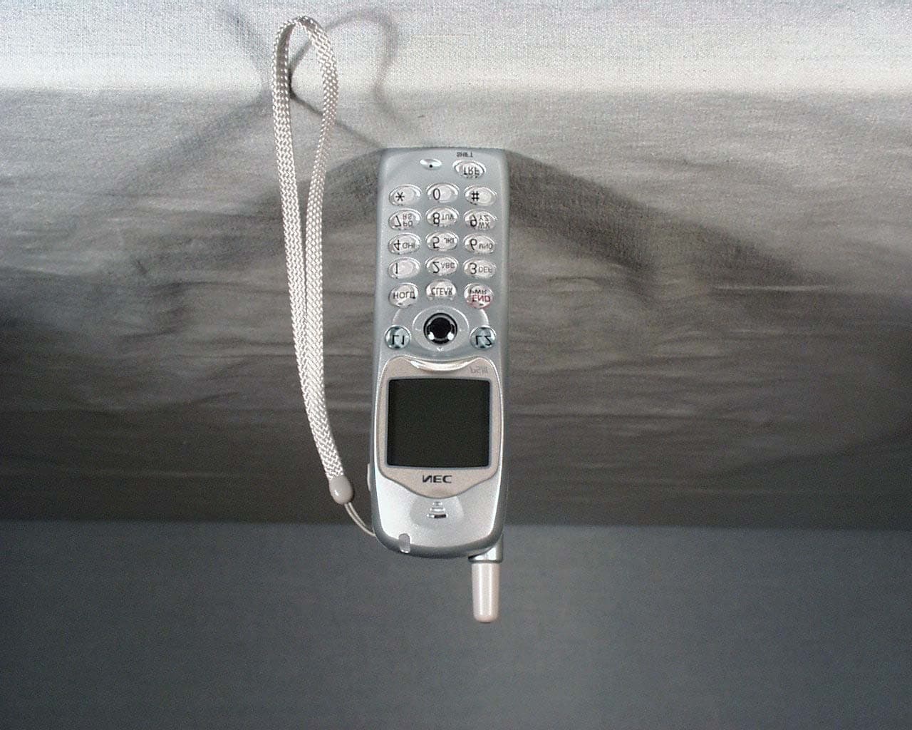
AY5PS3D
May 23, 2004Model PS3D Handset
Equipment Class
PUE - Part 15 Unlicensed PCS portable Tx held to ear
AY5SN531PSTH-A
Jun 29, 2003Model - SN531 PSTH-A
Equipment Class
PUE - Part 15 Unlicensed PCS portable Tx held to ear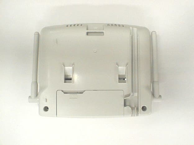
AY5SN992CSEO
Feb 09, 2000Unlicensed PCS Base Station
Equipment Class
PUB - Part 15 Unlicensed PCS Base Station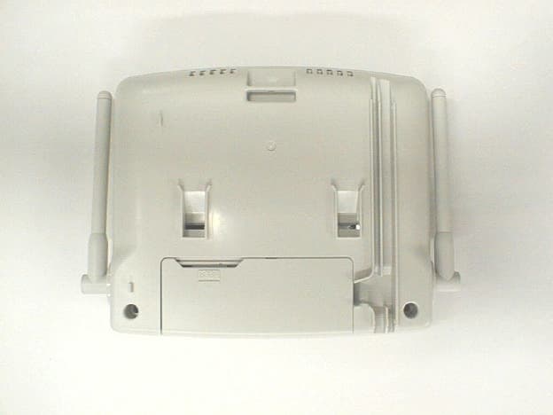
AY5SN999CSEQ
Jan 26, 2000Unlicensed PCS Base Station
Equipment Class
PUB - Part 15 Unlicensed PCS Base StationAY5SN531PSTH
Nov 02, 1997Handset Maximum output power: 54mW
Equipment Class
PUE - Part 15 Unlicensed PCS portable Tx held to ear