AZ489FT7011Integrated Transceiver
Motorola Solutions, Inc.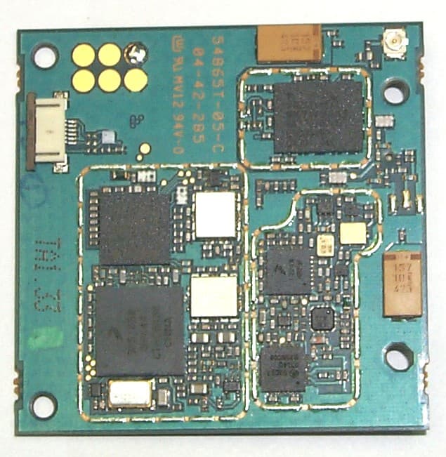
Click to zoom
Application Details
- Equipment Class
- TNB - Licensed Non-Broadcast Station Transmitter
- Date of Grant
- Jan 09, 2005
- Application Purpose
- Original Equipment
- Date of Application
- Jan 09, 2005
- Equipment Note
- Integrated Transceiver
- Frequency Range
- 896.00000000 - 901.00000000
- Company
- Motorola Solutions, Inc.
- Country
- United States
Documents & Files
Document Text
Text extracted from the exhibit documents filed with the FCC. Open a document above to read the original.
Users Manual
“DRAFT” Developer’s Guide iO200 OEM Module Module Description Version: 01.00-D06 Date: Nov 28, 2004 © Motorola Israel Ltd., 2004 A subsidiary of Motorola Inc. All rights reserved. Documentation Copyrights No duplication or distribution of this document or any portion thereof shall take place without the express written permission of Motorola. No part of this manual may be reproduced, distributed, or transmitted in any form or by any means, electronic or mechanical, for any purpose without the express written permission of Motorola. To order additional copies contact your Motorola sales representative. © 2004 Motorola All Rights Reserved 2 Table of Contents 1. Introduction......................................................................................................................................................................... 8 1.1. USING THIS GUIDE................................................................................................................................................ 8 1.2. PURPOSE ................................................................................................................................................................. 8 1.3. INTENDED AUDIENCE.......................................................................................................................................... 8 1.4. DISCLAIMER........................................................................................................................................................... 8 2. GENERAL NOTICES ........................................................................................................................................................ 9 2.1. Safety Notice - ATTENTION ................................................................................................................................... 9 2.2. FCC Regulation - Letter of Notice ............................................................................................................................ 9 3. THE INTEGRATOR'S TASK .......................................................................................................................................... 10 3.1. GENERAL .............................................................................................................................................................. 10 3.2. INTRODUCTION ................................................................................................................................................... 10 3.3. PLANNING THE PRODUCT AND CREATING THE DESIGN ......................................................................... 11 3.3.1. Developing a Usage Model................................................................................................................................. 11 3.3.2. Developing a Message Model............................................................................................................................. 11 3.3.3. Defining a Service Strategy ................................................................................................................................ 12 3.3.4. Defining Remote Diagnostic Functionality ........................................................................................................ 12 3.3.5. Investigating and Obtaining Regulatory Approval ............................................................................................. 13 3.4. DEVELOPING AND VALIDATING THE HARDWARE.................................................................................... 13 3.5. Designing the Hardware Platform ........................................................................................................................... 13 3.6. Considering Power Supply Options......................................................................................................................... 13 3.7. Selecting the Antenna.............................................................................................................................................. 14 3.8. Setting Up a Development Test Environment ......................................................................................................... 14 3.9. DEVELOPING SUPPORTING APPLICATION SOFTWARE ............................................................................. 14 3.10. TESTING AND APPROVING THE PRODUCT................................................................................................... 14 3.11. Setting Up a Final Test Environment ...................................................................................................................... 14 3.12. Installing and Field-Testing the Product.................................................................................................................. 14 3.13. RESOURCE ASSISTANCE ................................................................................................................................... 15 3.14. Integrating Engineering Support ............................................................................................................................. 15 3.15. ENVIRONMENTAL ISSUES ................................................................................................................................ 16 3.16. General Precautions................................................................................................................................................. 16 3.17. ESD Handling Precautions ...................................................................................................................................... 16 4. MODEL DESCRIPTION ................................................................................................................................................. 17 4.1. GENERAL ..............................................................................................................................…
Text truncated - open the document above for the full version.
Attestation Statements
FCC Filing Package for Motorola io200 Transceiver FCC ID: AZ489FT7011 Motorola Inc., 8000 W. Sunrise Blvd., Plantation, FL 33322, USA Page: 2- 1 Exhibit 2. Statement of Certification -- Pursuant to 47 CFR 2.907 The technical data supplied with this application, having been taken under my supervision is hereby duly certified. The following is a statement of my qualifications: B.Tech In Electrical Engineering, 1999, Ariel College, Israel. 5 years experience in RF design and measurement techniques. NAME: Yossi Druyan SIGNATURE: /s/ Yossi Druyan (signed) DATE: 12/06/2004 TITLE: RF Engineer I hereby certify that the above application was prepared under my direction and that to the best of my knowledge and belief, the facts set forth in the application and accompanying technical data are true and correct: NAME: Zami Schwartzman SIGNATURE: /s/ Zami Schwartzman (signed) DATE: 12/06/2004 TITLE: Engineering Manager
Cover Letter(s)
Applicant: Motorola Inc FCC ID: AZ489FT7011 21st Dec. 2004 Authorization & Evaluation Division Federal Communications Commission Laboratory 7435 Oakland Mills Road Columbia, MD 21046 Dear Sir Motorola Inc., 8000 West Sunrise Boulevard, Fort Lauderdale, Florida 33322, herein submits its application for Certification of the transmitter with FCC ID: AZ489FT7011. This OEM (Original Equipment Manufacturer) integrated transceiver module is similar to previously certified iO1500 integrated transceiver module with FCC ID: AZ492FT5826, and uses similar circuitry and software as previously certified i860 transceiver with FCC ID: AZ489FT5833. The variable output power (0.086 to 605 milliwatt) transmitter which is part of this transceiver is used in a SMR and EA SMR trunking system operating in the United States 806-825/851-870MHz and 896- 901/935-941 MHz frequency band. Certification is sought for, and performance data is provided. This transceiver module will be marketed as an Original Equipment Manufacturer (OEM) module. It shall be embedded in a variety of end products, as described in 47 CFR 2.1091(d)(4). It is supplied neither with battery nor antenna, only with an antenna connector. The characteristics of having an antenna connector and no antenna are like those of transmitters classified as a mobile device, as defined in 47 CFR 2.1091(b), rather than a handheld portable device as defined in 47 CFR 2.1093(b). Since Motorola neither manufactures nor supplies the antenna(s) that will be used in the final application of this product, it is not possible to measure the MPE of the actual device as it will be integrated into the end product. Therefore MPE calculation was done with the MPE General Population limits for a mobile device in Table 1(B) of 47 CFR 2.1310 as required by 47CFR 2.1091(c). This module will be marketed to OEMs, who will integrate it into their equipment, i.e. lap-top computers, portable/mobile terminals, vending machines, etc. Since the end product may, in some cases, be used within a digital device such as a laptop computer to be marketed in the United States, it is our expectation that the end product may bear a separate FCC identifier in accordance with 47 CFR 2.925(b). It will be the responsibility of the integrator to conduct appropriate RF exposure evaluation, provide user manual information and obtain FCC equipment authorization for the end product. It is our intention to provide the OEM party with a letter notifying them of the need to comply with 47 CFR part 2 subpart J, et. al., once a purchasing agreement has been reached. This transceiver is of the receive-first type described in International Telecommunications Union Recommendation ITU-R M.1221 entitled Technical And Operational Requirements For Cellular Multimode Mobile Radio Stations. It must first find, acquire and lock onto a control channel from a predefined set of control channel frequencies assigned to a companion Authorized base station (e.g. – FCC ID: ABZ89FC5792). Transmission is not possible until lock to a base station control Motorola Inc., 8000 West Sunrise Blvd., Plantation, FL 33322, USA Applicant: Motorola Inc FCC ID: AZ489FT7011 channel has been achieved, and then transmission is limited to digitally modulated service request bursts on the reverse control channel. Upon recognition of a proper request, the control channel base station transmitter will then assign the transceiver a traffic channel for transmission of digital voice, circuit-switched data or Packet-switched data from the set of frequencies for which the trunking system is licensed. It is expected that this time division multiplexed transceiver marketed in the United States will also be used for itinerant operation with companion Authorized Base Stations by users requesting trunked radio and telephone interconnect service while roaming outside the United States. In some countries the companion base stations are licensed to operate at frequencies in the 821-825/866- 870 MHz band in addition to some of those in the 806-825/851-870 MHz band normally used in United States SMR systems. Consequently, this transmitter has been designed to meet FCC requirements for operation in the 806-825 MHz band over the more global band of 806 - 825 MHz when used with a companion Authorized Base Station. Thus, performance data is provided to substantiate FCC compliant operation with a Companion Base Station over the broader 806 to 825 MHz band and the 935-940 MHz band. To facilitate global roaming it is kindly requested that a note be provided in the Grant, which states that this ‘receive first’ type of equipment is compliant for transmitter operation over the broader range 806-825 MHz when used with a compatible Authorized Base Station. This will aid equipment authorization in foreign countries, which accept a United States FCC Grant for Equipment Authorization, yet not jeopardize United States public safety or cellular systems licensed to operate in the 821-825 MHz frequency band since no compatible base station may be authorized on those frequencies in the United States. The subject transmitter complies with 47 CFR 90.203 of the rules in that the operator cannot directly program transmit frequencies using only the unit's normally accessible external controls. Enclosed is a complete Certification Application comprised of 15 Exhibits. Contact me at (954) 723 -5793 if you require any additional information. Sincerely, /s/ Mike Ramnath (signed) Manager, Regulatory Compliance Email: [email protected] Motorola Inc., 8000 West Sunrise Blvd., Plantation, FL 33322, USA Page: 13a- 2
Cover Letter(s)
FCC ID: AZ489FT7011 Date: 23rd December 2004 Authorization & Evaluation Division Federal Communications Commission Laboratory 7435 Oakland Mills Road Columbia, MD 21046 Subject: Application for Certification of Transmitter with FCC ID: AZ489FT7011. Dear Sir or Madam: Motorola is requesting that Exhibit 4 (Circuit Descriptions), Exhibit 5 (Schematic Diagrams), Exhibit 10 (Parts List and Tune-Up Procedures), and Exhibit 12 (Operational Description) not be made routinely available for public inspection. Motorola considers the information in these exhibits to be classified as trade secrets, pursuant to 47 CFR Section 0.457(d) and Section 552(b)(4) of the Freedom of Information Act. We are also requesting that the FCC mark Exhibit 3 (External Photos) and Exhibit 9, (Internal Photos) as Temporary Confidentiality as outlined in Public Notice DA 04-1705, dated June 15, 2004. This provision will give Motorola temporary confidentiality prior to product launch. Please mark Exhibits 4, 5, 10, and 12 as “Confidential” And Exhibit 3 and 9 as “Temporary Confidential”. Please contact me if you require any additional information. Sincerely, /s/ Mike Ramnath (signed) Manager, Regulatory Compliance Tel: (954) 723-5793 E-mail: [email protected] EXHIBIT 13b 8000 West Sunrise Boulevard, Fort Lauderdale, Florida 33322. USA
External Photos
FCC Filing Package for Motorola io200 Transceiver FCC ID: AZ489FT7011 Motorola Inc., 8000 West Sunrise Blvd., Plantation, FL 33322, USA Page: 3- 1 Exhibit 3. External Photographs -- Pursuant to 47 CFR 2.1033(c) 12 External photograph are identical to the internal photographs shown in Exhibit 9.
ID Label/Location Info
FCC Filing Package for Motorola io200 Transceiver FCC ID: AZ489FT7011 Motorola Inc., 8000 West Sunrise Blvd., Plantation, FL 33322, USA Page: 1- 1 Exhibit 1: Identification Label -- Pursuant to 47 CFR 2.925, 2.1065 and 2.1033(c) 11 1.1. Location Top side of the PCB. (See the attached photograph in exhibit 3) 1.2. Type The labels are white polyester film laminate with a pressure sensitive adhesive backing. The adhesive is a permanent type acrylic with minimum peel strength of 5 lbs/in. 1.3. Markings (Text ) Enlarged view of labels (showing FCC ID and manufacturer type number): Label 1 Label 2 FCC Filing Package for Motorola io200 Transceiver FCC ID: AZ489FT7011 Motorola Inc., 8000 West Sunrise Blvd., Plantation, FL 33322, USA Page: 1- 2 Exhibit 1A: General Information 1A.1. Production Plans Quantity production is planned. 1A.2. Application References -- Pursuant to 47 CFR 2.948 and 2.1061 Reference is made to the following Motorola "Application References" Hermon Labs, located in Binyamina Israel is listed with FCC and Industry Canada as follows: 1. FCC OATS registration number is: 90624 2. FCC Anechoic chamber registration number is: 90623 3. Industry Canada OATS registration number is: IC 2186-1 4. Industry Canada anechoic chamber registration number is: IC 2186-2 5. Accredited by A2LA, Certificate number: 0839-01 1A.3. Data Submittal Procedure Data located in Exhibit 6 is supplied in accordance with Part 2, Sub-part J and Part 90, Sub-part I and Sub-part S of the Commission’s rules. 1A.4. Similar, currently Certified Transmitter FCC ID: AZ489FT5833
Internal Photos
FCC Filing Package for Motorola io200 Transceiver FCC ID: AZ489FT7011 iDEN, Motorola Inc., 8000 West Sunrise Blvd., Plantation, FL 33322, USA http://ml800.motorola.com/ http://www.mot.com/iden Page: 9- 1 Exhibit 9. Internal Photographs -- Pursuant to 47 CFR 2.1033(c)12 Photograph 9-1: Top side of module board. Photograph 9-2: Top side of module board with shields removed Photograph 9-3: Bottom side of module board. Photograph 9-4: Bottom side of module board with shields removed.
RF Exposure Info
Certificate No. 1449-01 CGISS EME Form-SAR-Rpt-Rev. 2.00 Page 1 of 3 CGISS EME Test Laboratory 8000 West Sunrise Blvd Fort Lauderdale, FL. 33322 MPE Compliance Report Note: This report shall not be reproduced without written approval from an officially designated representative of the Motorola EME Laboratory. Based on the information and the testing results provided herein, the undersigned certifies that when used as stated in the operating instructions supplied, said product complies with the national and international reference standards and guidelines listed in section 2.0 of this report. Signature on file 12/10/04 ____________________________________________________________ _________________________ Ken Enger Date Approved Senior Resource Manager, Laboratory Director, CGISS EME Lab Date of Report: December 10, 2004 Report Revision(s): Rev. A Device Manufacturer: Motorola Device Description: iO200 module: 806-825 and 896-901MHz, 1:6, 1:3, 81:120, 1:12 TDMA; 64 QAM, 16 QAM & QPSK Modulation; 0.6 W Pulse average nominal; GPS capable Classification: Occupational/Controlled Exposure FCC ID: AZ489FT7011 Device Model: FLF6011A Responsible Engineer: Stephen C. Whalen, Sr. EME Engineer Author: Stephen C. Whalen, Sr. EME Engineer Certificate No. 1449-01 CGISS EME Form-SAR-Rpt-Rev. 2.00 Page 2 of 3 REVISION HISTORY Date Revision Comments 12/2/04 O Original Release 12/10/04 A iM200 was changed to iO200 Certificate No. 1449-01 CGISS EME Form-SAR-Rpt-Rev. 2.00 Page 3 of 3 MPE Analysis The Motorola CGISS EME Laboratory has evaluated the iO200 model FLF6011A FCC ID AZ489FT7011 for RF Exposure Compliance. Due to the “component” nature of this product it is not possible to conduct EME testing because Motorola neither manufactures nor supplies the antenna(s) and host housing(s) that will be used in future systems integrations. Therefore this product will be evaluated as a mobile device per 47 CFR §1.1310 titled “Radio frequency radiation exposure limits”, generally referred to as Maximum Permissible Exposure (MPE) limits. A mobile device is defined as a transmitting device designed to be used in other than fixed locations and to generally be used in such a way that a separation distance of at least 20cm is maintained between the body of the user and nearby persons and the antenna. Although Motorola does not supply an antenna intended for use by the end user, a Systems Integrator Evaluation Board is available that includes a monopole antenna with a maximum gain of +1.4 dBi. The “Developer’s Guide” for this product instructs the Systems Integrator to transmit only when the operator and nearby persons are at least 20 cm from the antenna. Using OET Bulletin 65 formulas (listed below) the MPE of a radiating structure can be predicted when the distance, conducted power, and antenna gain, are known. Details are as follows: Model: FLF6011A Frequency Range: 806-825 and 896-901MHz Technology Duty Cycle: TDMA 1:6, 1:3 and 81:120 Maximum Power: 0.7 watts Time averaged Power (P): Maximum sourced based time-averaged transmit power is 472mW in 81:120 mode. MPE limit: 0.54mW/cm^2 at 806MHz (General Population MPE limit = f/1500) Distance (R): 20cm Antenna Gain (G): +7.3dBi maximum EIRP: 2.54W maximum The predicted RF Power Density based on the above information and OET Bulletin 65 is 0.51mW/cm^2 which is below the FCC General Population/Uncontrolled Limit of 0.54mW/cm^2. This result for a maximum antenna gain of +7.3 dBi also clearly demonstrates compliance for a +1.4 dBi antenna as used on the Systems Integrator Evaluation Board. OET Bulletin 65 Edition 97-01 Section 2: Prediction Methods Calculations can be made to predict RF field strength and power density levels around typical RF sources. For example, in the case of a single radiating antenna, a prediction for power density in the far-field of the antenna can be made by use of the general Equations (3) or (4) below. These equations are generally accurate in the far-field of an antenna but will over-predict power density in the near field, where they could be used for making a "worst case" or conservative prediction. 2 4R PG S π = (3) Where: S = power density (mW/cm^2) P = power input to the antenna (mW) G = power gain of the antenna in the direction of interest relative to an isotropic radiator R = distance to the center of radiation of the antenna (cm) Or 2 4R EIRP S π = (4) Where: EIRP = equivalent (or effective) isotropically radiated power
Test Report
FCC Filing Package for Motorola io200 Transceiver FCC ID: AZ489FT7011 Motorola Inc., 8000 W. Sunrise Blvd., Plantation, FL 33322, USA Page: 6- 1 Exhibit 6: Measured Data -- Pursuant 47 CFR. 2.1041 6.1 Transmitter Power The transmitter is a variable power type used in a SMR trunking system. Output power (as defined in 47 CFR 90.7) is dynamically controlled as described in Exhibit 12. 6.1.1 Maximum Output Power Rating -- Pursuant 47 CFR 2.1033(c) 7 and 90.635(d)) Maximum output power rating: 700 milliwatts (28.45 dBm), pulse average power Note 1: Nominal output power rating: 600 milliwatts (27.78 dBm) (Pulse average power). Note 2: These ratings are compliant with the FCC maximum of 100 watts (50 dBm) for Mobile stations Note 3: The term pulse average power is used to specify the power that would be measured during the intervals of recurrent TDM transmission pulses by an average responding RF power meter. Power expressed in this manner is independent of the TDM duty cycle, and facilitates RF system coverage analysis. 6.1.2 Operating output power range -- Pursuant 47 CFR 2.1033(c) 6) Maximum tuned output power will vary over a range of 500 to 700 milliwatts (maximum pulse average power) to a minimum power of 39 dB below maximum tuned output power. 6.1.3 DC power used by final amplifier device -- Pursuant 47 CFR 2.1033(c) 8) In order to prevent the malfunctions that can occur due to directly measuring the DC characteristics of the final RF amplifying stage, data was obtained by measuring the entire radio DC current and is reported herein for the entire radio. The DC current and the RF output power was measured with a special RF/DC test fixture set to supply the radio with the nominal supply voltage of 4.0 V. The characteristics were measured during a transmission pulse and are listed in the Table 6-1. 800 MHz band 900 MHz band Characteristics At the maximum power setting At the minimum power setting At the maximum power setting At the minimum power setting DC Voltage (Volts) 4.0 4.0 4.0 4.0 DC Current (A) 1.15 0.61 1.1 0.60 Output Power (mW) 603 0.0857 605 0.0862 Table 6-1 Characteristics for 800 and 900 MHz bands FCC Filing Package for Motorola io200 Transceiver FCC ID: AZ489FT7011 Motorola Inc., 8000 W. Sunrise Blvd., Plantation, FL 33322, USA Page: 6- 2 6.2 Modulation Characteristics and Necessary Bandwidth -- Pursuant 47 CFR 2.1033(c) 13, 2.1047(d) & 2.202 Digitally encoded digital data is transmitted in groups of four sub-channels at a 4 kHz rate using M-ary symbols mapped to predetermined fixed magnitude and phase components within 1 of 3 constellations associated with a particular modulation scheme. One to four groups of four sub-channel streams are combined using frequency division multiplexing to form the modulated waveform. Figure 6-3 illustrates symbol mapping to one of the four QPSK sub-channels constellations. Figure 6-4 illustrates symbol mapping to one of the four 16QAM sub-channels constellation. Figure 6-4a illustrates symbol mapping to one of the four 64QAM sub-channels constellation. For Quad-QPSK modulation, this mapping adjusts the amplitude and phase variations of the baseband signal to one of 4 points on the constellation. For Quad- 16QAM modulation, this mapping adjusts the amplitude and phase variations of the baseband signal to one of 16 points on the constellation. For Quad-64 modulation, this mapping adjusts the amplitude and phase variations of the baseband signal to one of 64 points on the constellation. The bandwidth of the modulating signals is limited by the pair of modulation limiting low pass filters within the modem block function of U801 (see Figure 4-2 in Exhibit 4.3). These filters serve to limit out-of-band and spurious emissions due to modulation. The necessary bandwidth of the sub-channels is limited to 4.8 kHz by the pair of modulation limiting low pass filters. The transfer response of these filters is depicted in Figure 6-1 where the filter excess bandwidth coefficient of 0.2 is shown. This excess bandwidth leads to the necessary bandwidth calculation of (1 + 0.2) x (4 kHz) = 4.8 kHz. Since the sub-channels are spaced 4.5 kHz apart, and the groups that each contain 4 sub-channels are spaced apart in integer multiples of 25 kHz, the necessary bandwidth of the composite 4 sub-channel symbol streams (single group) is 4.8 + (3 x 4.5) = 18.3 kHz and the necessary bandwidth of the entire waveform depends on the number and combination of groups transmitted. Figure 6-2 illustrates all group combinations and corresponding bandwidths. Below in Table 6-2 is a description of each waveform case. Case Description (Figure) Number of Groups Number Of Sub-channels Emission Designator Mask Figure 1 When Transmitting Voice, data or fax on one 25kHz channel (6.2.1) 1 4 18K3D7W 6-5 to 6-16 2 When Transmitting data on 2 adjacent 25kHz channels (6-2 (Adjacent)) 2 8 43K3D7D 6-17 to 6-22 3 When Transmitting data on 3 adjacent 25kHz channels (6-3) 3 12 68K3D7D 6-23 to 6-28 When Transmitting data on the 2 outer 25kHz channels of 4 25kHz channels (6-2(outer)) 2 8 93K3D7D 6-35 to 6-40 4 When Transmitting data on 4 adjacent 25kHz channels (6-4) 4 16 93K3D7D 6-29 to 6-34 Table 6-2: Waveform Description of all transmitted cases. The designator for emissions in case 2 and 3 is determined by adding N x 25 to the first 2 digits, when N = the number of channels. The designator for case 4 is determined by adding 3 x 25 to the fist 2 digits because the outer channels are 3 channels apart. D is used for the last character when only data is transmitted, not telephony. FCC Filing Package for Motorola io200 Transceiver FCC ID: AZ489FT7011 Motorola Inc., 8000 W. Sunrise Blvd., Plantation, FL 33322, USA Page: 6- 3 0.707 02k2.4k-2k H(f)=root raised α =0.2 Modulation Low Pass Filter Res ponse ω o ω where ω o = 2000 and ω = (1+ α ) ω o = 2400Hz 1for |f| <2 ω o - ω cos 2 ( π /4 (|f| + ω - 2 ω o )/( ω - ω o ))for 2 ω o - ω < |f|< ω 0for |f| > ω { H(f)= Figure 6-1: Modulation Low Pass Filter Resp…
Text truncated - open the document above for the full version.
Contact Information
Applicant
Arine Lee(Certification Manager)
Test Firm
Hermon Laboratories Ltd.Alexander Usoskin
Technical Specifications
| # | Rule Parts | Frequency Range | Power Output | Emission | Tolerance |
|---|---|---|---|---|---|
| 8 | 9 | 896 MHz - 901 MHz | 700.00 mW | 93K3D7D | 0.1 ppm |
Other Applications from Motorola Solutions, Inc.

AZ489FT4980
Sep 08, 2026Portable two way radio
Equipment Class
TNF - Licensed Non-Broadcast Transmitter Held to FaceAZ489FT4981
Aug 14, 2026Handheld Portable - TANAPA BPR 45 400-470 MHZ 4W NKP
Equipment Class
TNF - Licensed Non-Broadcast Transmitter Held to Face
AZ489FT7187
Jul 13, 2026Portable 2-Way Radio with Bluetooth, Bluetooth LE, WIFI 2.4GHz, WIFI 5GHz, LTE
Equipment Class
DSS - Part 15 Spread Spectrum TransmitterAZ499FT6031
May 11, 2026Operation Critical Wireless Earpiece PTT
Equipment Class
DSS - Part 15 Spread Spectrum Transmitter
AZ499FT5879
Dec 19, 20252-way Portable Radio with BT, BTLE, WIFI, NFC and LTE
Equipment Class
DSS - Part 15 Spread Spectrum Transmitter