BEJMU42PZ41VPlasma Monitor
LG Electronics USA, Inc.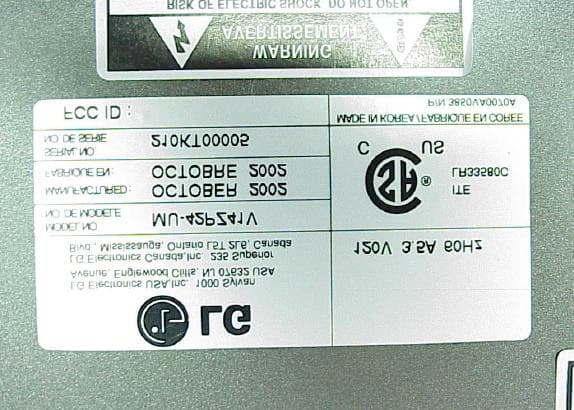
Click to zoom
Application Details
- Equipment Class
- JBP - Part 15 Class B Computing Device Peripheral
- Date of Grant
- Dec 17, 2002
- Application Purpose
- Original Equipment
- Date of Application
- Dec 17, 2002
- Equipment Note
- Plasma Monitor
- Company
- LG Electronics USA, Inc.
- Country
- United States
Documents & Files
Document Text
Text extracted from the exhibit documents filed with the FCC. Open a document above to read the original.
Users Manual
PLASMA MONITOROWNER’S MANUAL Please read this owner’s manual carefully before operating theMonitor.Retain it for future reference.Record model number and serial number of the Monitor.See the label attached on the back of the Monitor and quotethis information to your dealer when you require service.Model number : Serial number : MODELS : MU-42PZ41V MU-42PZ41VAMU-42PZ41VBMU-42PZ41VKMU-42PZ41VRMU-42PZ41VS P/NO : 3828VA0361C (RF02RA) 2 WARNING WARNING: TO REDUCE THE RISK OF ELECTRIC SHOCK DO NOT REMOVE COVER (OR BACK). NO USER SERVICEABLE PARTS INSIDE. REFER TO QUALIFIED SERVICE PERSONNEL. The lightning flash with arrowhead symbol, within an equilateral triangle, is intended to alert the user to the presence of uninsulated “dangerous voltage” within the product’s enclosure that may be of sufficient magnitude to constitute a risk of electric shock to persons. The exclamation point within an equilateral triangle is intended to alert the user to the presence of important operating and maintenance (servicing) instructions in the literature accompanying the appliance. WARNING: TO PREVENT FIRE OR SHOCK HAZARDS, DO NOT EXPOSE THIS PRODUCT TO RAIN OR MOIS- TURE. FCC NOTICE • A Class B digital device This equipment has been tested and found to comply with the limits for a Class B digital device, pursuant to Part 15 of the FCC Rules. These limits are designed to provide reasonable protection against harmful interference in a residential installation. This equipment generates, uses and can radiate radio frequency energy and, if not installed and used in accordance with the instructions, may cause harmful interference to radio communications. However, there is no guarantee that interference will not occur in a particular instal- lation. If this equipment does cause harmful interference to radio or television reception, which can be deter- mined by turning the equipment off and on, the user is encouraged to try to correct the interference by one or more of the following measures: - Reorient or relocate the receiving antenna. - Increase the separation between the equipment and receiver. - Connect the equipment into an outlet on a circuit different from that to which the receiver is connected. - Consult the dealer or an experienced radio/TV technician for help. • Any changes or modifications not expressly approved by the party responsible for compliance could void the user’s authority to operate the equipment. WARNING RISK OF ELECTRIC SHOCK DO NOT OPEN WARNING TO REDUCE THE RISK OF FIRE AND ELECTRIC SHOCK, DO NOT EXPOSE THIS PRODUCT TO RAIN OR MOISTURE. 3 Important safeguards for you and your new product Your product has been manufactured and tested with your safety in mind. However, improper use can result in potential electrical shock or fire hazards. To avoid defeating the safeguards that have been built into your new product, please read and observe the following safety points when installing and using your new product, and save them for future reference. Observing the simple precautions discussed in this booklet can help you get many years of enjoyment and safe operation that are built into your new product. This product complies with all applicable U.S. Federal safety requirements, and those of the Canadian Standards Association. 1. Read Instructions All the safety and operating instructions should be read before the product is operated. 2. Follow Instructions All operating and use instructions should be followed. 3. Retain Instructions The safety and operating instructions should be retained for future reference. 4. Heed Warnings All warnings on the product and in the operating instructions should be adhered to. 5. Cleaning Unplug this product from the wall outlet before cleaning. Do not use liquid cleaners or aerosol cleaners. Use a damp cloth for cleaning. 6. Water and Moisture Do not use this product near water, for example, near a bath tub, wash bowl, kitchen sink, or laundry tub, in a wet basement, or near a swimming pool. 7. Accessories Carts and Stands Do not place this product on a slippery or tilted surface, or on an unstable cart, stand, tripod, bracket, or table. The product may slide or fall, causing serious injury to a child or adult, and serious damage to the product. Use only with a cart, stand, tripod, brack- et, or table recommended by the manufacturer, or sold with the product. Any mounting of the product should follow the manu- facturer’s instructions, and should use a mounting accessory recommended by the manufacturer. 8. Transporting Product A product and cart combination should be moved with care. Quick stops, excessive force, and uneven surfaces may cause the product and cart combination to overturn. 9. Attachments Do not use attachments not recommended by the product man- ufacturer as they may cause hazards. 10. Ventilation Slots and openings in the cabinet are provided for ventilation and to ensure reliable operation of the product and to protect it from overheating, and these openings must not be blocked or covered. The openings should never be blocked by placing the product on a bed, sofa, rug, or other similar surface. This prod- uct should not be placed in a built-in installation such as a book- case or rack unless proper ventilation is provided or the manu- facturer’s instructions have been adhered to. 11. Power Sources This product should be operated only from the type of power source indicated on the marking label. If you are not sure of the type of power supply to your home, consult your product dealer or local power company. For products intended to operate from battery power, or other sources, refer to the operating instruc- tions. 12. Power-Cord Polarization This product is equipped with a three-wire grounding type plug, a plug having a third (grounding) pin. This plug will only fit into the grounding-type power outlet. This is a safety feature. If you are unable to insert the plug into the outlet, contact your electri- cian to replace your obsolete outlet. Do not…
Text truncated - open the document above for the full version.
Block Diagram
Page 42 LG Electronics USA Plasma Monitor FCC ID. : BEJMU42PZ41V Block Diagram
Cover Letter(s)
Page 3 LG Electronics USA Plasma Monitor FCC ID. : BEJMU42PZ41V Letter of Modification Date: December 14, 2002 Subject : RFI related modifications incorporated into unit with FCC ID. : BEJMU42PZ41V Dear Sir, This letter services as our declaration that all modifications listed below are implemented in the sample submitted for pre-grant testing. We further declare that the same modifications will be implemented into all production unit to enhance compliance of the unit to FCC limits. The modifications include the following : 1. Add gaskets on the bracket of the A/V FIX board. @ Refer to Page 11 (Figure 9, Point 1) 2. Add a ferrite core on the L/R wires. (From the speaker board to the main board) @ Refer to Page 11 (Figure 10, Point 2) 3. Add ferrite cores on the four flat cables separately. @ Refer to Page 12 (Figure 11, Point 3) 4. Add conductive fabric tape on the connector of the connecting cable. (Between the main board and the control board). @ Refer to Page 18 (Figure 23, Point 4) 5. Bond two ferrite cores on the D-Sub data cable. @ Refer to Page 34 (Figure 56, Point 5) 6. Bond two ferrite cores on the DVI data cable. @ Refer to Page 34 (Figure 56, Point 6) 7. Bond a ferrite core on the speaker’s cable separately. @ Refer to Page 34 (Figure 56, Point 7) 8. Add a ferrite core on the remote control cable (Close to the EUT). @ Refer to Radiated Test Photo (Back View) – Report No.: TTEMC-F91196, Page 32 If you have any questions or require any other information please do not hesitate to contact our agent. Sincerely Yours, W.H. OH, Team Leader Foreign Standards Research Lab. TV Pnant, LG Electronics Inc.
External Photos
Page 7 LG Electronics USA Plasma Monitor FCC ID. : BEJMU42PZ41V Photographs Figure 1 Plasma MonitorSpeakersRemote ControlData Cables (General View) Figure 2 General Appearance (Rear View) Page 8 LG Electronics USA Plasma Monitor FCC ID. : BEJMU42PZ41V Figure 3 General Appearance/ Back Side (Product’s Label) Figure 4 General Appearance (Rear & Bottom View) Page 9 LG Electronics USA Plasma Monitor FCC ID. : BEJMU42PZ41V Figure 5 General Appearance/ Rear Side (I/O Connectors) Figure 6 Internal Frame & Removed Back Cover
ID Label/Location Info
Page 5 LG Electronics USA Plasma Monitor FCC ID. : BEJMU42PZ41V Label Drawing l Label Placement Location (Rear of EUT) FC LABEL
Internal Photos
Page 10 LG Electronics USA Plasma Monitor FCC ID. : BEJMU42PZ41V Figure 7 Internal View Figure 8 Fans Page 11 LG Electronics USA Plasma Monitor FCC ID. : BEJMU42PZ41V Figure 9 Bracket of AV FIX Board Figure 10 Internal View (EMI Core) 1. 2. Page 12 LG Electronics USA Plasma Monitor FCC ID. : BEJMU42PZ41V Figure 11 Internal View (EMI Core) Figure 12 Internal View (Remove AV FIX Board) 3. 3. 3. 3. Page 13 LG Electronics USA Plasma Monitor FCC ID. : BEJMU42PZ41V Figure 13 AV FIX Board (Component Side) Figure 14 AV FIX Board (Solder Side) Page 14 LG Electronics USA Plasma Monitor FCC ID. : BEJMU42PZ41V Figure 15 Control Key Board (Component Side) Figure 16 Control Key Board (Solder Side) Page 15 LG Electronics USA Plasma Monitor FCC ID. : BEJMU42PZ41V Figure 17 Internal View (Remove Y Drive Boards) Figure 18 Y Drive Board – Top & Y Drive Board – Bottom (Component Side) Page 16 LG Electronics USA Plasma Monitor FCC ID. : BEJMU42PZ41V Figure 19 Y Drive Board – Top & Y Drive Board – Bottom (Solder Side) Figure 20 Y Board (Component Side) Page 17 LG Electronics USA Plasma Monitor FCC ID. : BEJMU42PZ41V Figure 21 Y Board (Solder Side) Figure 22 Internal View (Remove Main Board) Page 18 LG Electronics USA Plasma Monitor FCC ID. : BEJMU42PZ41V Figure 23 Main Board (Componen Side) Figure 24 Main Board (Solder Side) 4. Page 19 LG Electronics USA Plasma Monitor FCC ID. : BEJMU42PZ41V Figure 25 Control Board (Component Side) Figure 26 Control Board (Solder Side) Page 20 LG Electronics USA Plasma Monitor FCC ID. : BEJMU42PZ41V Figure 27 Internal View (Remove Power Board) Figure 28 Power Board (Component Side) Page 21 LG Electronics USA Plasma Monitor FCC ID. : BEJMU42PZ41V Figure 29 Power Board (Solder Side) Figure 30 Switch Board (Component Side)
Internal Photos
Page 22 LG Electronics USA Plasma Monitor FCC ID. : BEJMU42PZ41V Figure 31 Switch Board (Solder Side) Figure 32 Z-SUS Board (Component Side) Page 23 LG Electronics USA Plasma Monitor FCC ID. : BEJMU42PZ41V Figure 33 Z-SUS Board (Solder Side) Figure 34 Z-SUS Drive Board (Component Side) Page 24 LG Electronics USA Plasma Monitor FCC ID. : BEJMU42PZ41V Figure 35 Z-SUS Drive Board (Solder Side) Figure 36 Z-CNT TOP Board & Z-CNT Bottom Board (Component Side) Page 25 LG Electronics USA Plasma Monitor FCC ID. : BEJMU42PZ41V Figure 37 Z-CNT TOP Board & Z-CNT Bottom Board (Solder Side) Figure 38 X Drive Board – Left & X Drive Board – Right (Component Side) Page 26 LG Electronics USA Plasma Monitor FCC ID. : BEJMU42PZ41V Figure 39 X Drive Board – Left & X Drive Board – Right (Solder Side) Figure 40 Speaker Control Board (Component Side) Page 27 LG Electronics USA Plasma Monitor FCC ID. : BEJMU42PZ41V Figure 41 Speaker Control Board (Solder Side) Figure 42 Internal Frame (Display Panel, Back View) Page 28 LG Electronics USA Plasma Monitor FCC ID. : BEJMU42PZ41V Figure 43 Label View of Display Panel Figure 44 Speakers (Appearance, Front View) Page 29 LG Electronics USA Plasma Monitor FCC ID. : BEJMU42PZ41V Figure 45 Speakers (Appearance, Back View) Figure 46 Speaker (Appearance, Product’s Label) Page 30 LG Electronics USA Plasma Monitor FCC ID. : BEJMU42PZ41V Figure 47 Speaker (Removed Cover, Frame of Internal) Figure 48 Speaker (Internal View) Page 31 LG Electronics USA Plasma Monitor FCC ID. : BEJMU42PZ41V Figure 49 Speaker (Internal View) Figure 50 Remote Control (Appearance, Front View) Page 32 LG Electronics USA Plasma Monitor FCC ID. : BEJMU42PZ41V Figure 51 Remote Control (Appearance, Front View) Figure 52 Remote Control (Appearance, Back View) Page 33 LG Electronics USA Plasma Monitor FCC ID. : BEJMU42PZ41V Figure 53 Remote Control (Remove Case Covers, Frame of Internal) Figure 54 Remote Control (PCB View, Back Side) Page 34 LG Electronics USA Plasma Monitor FCC ID. : BEJMU42PZ41V Figure 55 Remote Control (PCB View, Front Side) Figure 56 Cables (RGB/D-SubRGB/DVISpeaker CableAC Power Cord) 7. 5. 6. 7.
Test Report
FCC ID: BEJMU42PZ41V Page 1 of 37 Taiwan Tokin EMC Eng. Corp. Report No.: TTEMC-F91196 APPLICATION FOR CERTIFICATION (FCC CFR47 PART 15 DIGITAL DEVICE) On Behalf of LG Electronics USA PLASMA MONITOR Model(1)MU-42PZ41V (2)P42W24P FCC IDBEJMU42PZ41V Brand(1)LG (2)ZENITH Prepared for : LG Electronics USA 6133 N River Rd., Suite 1100, Rosemont IL US. Prepared by : Taiwan Tokin EMC Eng. Corp. No. 53-11, Tin-Fu Tsun, Lin-Kou, Taipei Hsien, Taiwan, R.O.C. Tel: (02) 2609-9301, 2609-2133 Fax: (02) 2609-9303 File Number ATM-G911116 Report Number TTEMC-F91196 Date of Test Nov. 23 ~ Dec. 11, 2002 Date of Report Dec. 14, 2002 FCC ID: BEJMU42PZ41V Page 2 of 37 Taiwan Tokin EMC Eng. Corp. Report No.: TTEMC-F91196 TABLE OF CONTENTS Description Page TEST REPORT CERTIFICATION........................................................................................................3 1. GENERAL INFORMATION.........................................................................................................4 1.1. Description of Device (EUT)..........................................................................................................4 1.2. Tested Supporting System Details...................................................................................................5 1.3. Description of Test Facility.............................................................................................................8 1.4. Measurement Uncertainty...............................................................................................................8 2. POWERLINE CONDUCTED TEST.............................................................................................9 2.1. Test Equipment..............................................................................................................................9 2.2. Block Diagram of Test Setup..........................................................................................................9 2.3. Conducted Powerline Emission Limit (CISPR 22, Class B)..............................................................9 2.4. EUT’s Configuration during Compliance Measurement..................................................................10 2.5. Operating Condition of EUT.........................................................................................................10 2.6. Test Procedure.............................................................................................................................11 2.7. Line Conducted RF Voltage Measurement Results.........................................................................11 3. RADIATED EMISSION TEST....................................................................................................22 3.1. Test Equipment............................................................................................................................22 3.2. Block Diagram of Test Setup........................................................................................................22 3.3. Radiation Limit (CISPR 22, Class B)............................................................................................23 3.4. EUT’s Configuration during Compliance Measurement..................................................................23 3.5. Operating Condition of EUT.........................................................................................................23 3.6. Test Procedure.............................................................................................................................24 3.7. Radiated Emission Noise Measurement Results.............................................................................25 4. MODIFICATIONS TO EUT........................................................................................................27 5. DEVIATION TO TEST SPECIFICATIONS.............................................................................28 6. PHOTOGRAPHS..........................................................................................................................29 6.1. Photos of Powerline Conducted Measurement................................................................................29 6.2. Photos of Radiated Measurement at Open Field Test Site................................................................32 6.3. Photos of Radiated Measurement at Semi-Anechoic Chamber.........................................................34 APPENDIX (Radiated Test Data at Semi-Anechoic Chamber)............................................................37 FCC ID: BEJMU42PZ41V Page 3 of 37 Taiwan Tokin EMC Eng. Corp. Report No.: TTEMC-F91196 TEST REPORT CERTIFICATION Applicant LG Electronics USA Manufacturer LG Electronics Inc. FCC ID BEJMU42PZ41V EUT Description PLASMA MONITOR (A) MODEL NO. (1)MU-42PZ41V (2)P42W24P (B) SERIAL NO. 210KT00005 (C) BRAND (1)LG (2)ZENITH (D) POWER SUPPLY AC 120V, 60Hz Measurement Procedure Used: FCC RULES AND CISPR 22 (DOCKET NO. 92-152, SEP. 1993) AND FCC / ANSI C63.4-1992 (FCC CFR 47, Part 15 Subpart B/2002 and CISPR 22/1997) (NOTE These results are deemed satisfactory evidence of compliance with ICES-003 of the Canadian Interference-Causing Equipment Regulations) The device described above was tested by TAIWAN TOKIN EMC ENG. CORP. to determine the maximum emission levels emanating from the device. The maximum emission levels were compared to the CISPR 22 Class B limits both radiated and conducted emissions. The measurement results are contained in this test report and TAIWAN TOKIN EMC ENG. CORP. is assumed full responsibility for the accuracy and completeness of these measurements. Also, this report shows that the EUT to be technically compliance with the FCC official limits. This report applies to above tested sample only. This report shall not be reproduced in part without written approval of Taiwan Tokin EMC Eng. Corp. Date of Test : Nov. 23 ~ Dec. 11, 2002 Prepared By: (Monica Chang/Officer) Test En…
Text truncated - open the document above for the full version.
Test Report
FCC ID: BEJMU42PZ41V Page 16 of 37 Taiwan Tokin EMC Eng. Corp. Report No.: TTEMC-F91196 FCC ID: BEJMU42PZ41V Page 17 of 37 Taiwan Tokin EMC Eng. Corp. Report No.: TTEMC-F91196 FCC ID: BEJMU42PZ41V Page 18 of 37 Taiwan Tokin EMC Eng. Corp. Report No.: TTEMC-F91196 FCC ID: BEJMU42PZ41V Page 19 of 37 Taiwan Tokin EMC Eng. Corp. Report No.: TTEMC-F91196 FCC ID: BEJMU42PZ41V Page 20 of 37 Taiwan Tokin EMC Eng. Corp. Report No.: TTEMC-F91196 FCC ID: BEJMU42PZ41V Page 21 of 37 Taiwan Tokin EMC Eng. Corp. Report No.: TTEMC-F91196 FCC ID: BEJMU42PZ41V Page 22 of 37 Taiwan Tokin EMC Eng. Corp. Report No.: TTEMC-F91196 3. RADIATED EMISSION TEST 3.1. Test Equipment The following test equipment are used during the radiated emission tests 3.1.1. At Semi-Anechoic Chamber Item Type Manufacturer Model No. Serial No. Last Cal. Cal. Interval 1. Spectrum Analyzer HP 8593EM 3826A00248 Sep. 23, 02’ 1 Year 2. Pre-Amplifier HP 8447D 2944A06305 Mar. 05, 02’ 1 Year 3. Broadband Antenna Schwarzbeck BBA9106 A3L Feb. 24, 02‘ 1 Year 4. Broadband Antenna Schwarzbeck UHALP9108-A 0138 Feb. 24, 02‘ 1 Year 3.1.2. At No. 6 Open Test Site Item Type Manufacturer Model No. Serial No. Last Cal. Cal. Interval 1. Test Receiver R&S ESVP 879691/036 Jul. 09, 02’ 1 Year 2. Spectrum Analyzer Anritsu MS2601A MT28657 Aug. 23, 02’ 1 Year 3. Broadband Antenna CHASE VBA6106A 1262 Nov. 26, 02’ 1 Year 4. Broadband Antenna CHASE UPA6109 1063 Nov. 26, 02’ 1 Year 3.2. Block Diagram of Test Setup 3.2.1. Block Diagram of connection between EUT and simulators AC SOURCE TV PATTERN GENERATOR PERSONAL SYSTEM KEYBOARD PLASMA MONITOR (EUT) PRINTER USB MOUSE #1#2 MOUSE SPEAKER SPEAKER MODEM : FERRITE CORE LCD MONITOR DVD PLAYER a b a: D-Sub Cable (Analog) b: DVI Cable (Digital) REMOTE CABLE HUB WALKMAN MICROPHONE FCC ID: BEJMU42PZ41V Page 23 of 37 Taiwan Tokin EMC Eng. Corp. Report No.: TTEMC-F91196 3.2.2. Semi-Anechoic Chamber (3M) & Open Field Test Site (10M) Setup Diagram 3.3. Radiation Limit (CISPR 22, Class B) All emanations from a class B computing devices or system, including any network of conductors and apparatus connected thereto, shall not exceed the level of field strengths specified below: FREQUENCY DISTANCE FIELD STRENGTHS LIMITS (MHz) (Meters) (dBμV/m) 30 ~ 230 10 (3) 30 (40) 230 ~ 1000 10 (3) 37 (47) Note (1) The tighter limit applies at the edge between two frequency bands. (2) Distance refers to the distance in meters between the measuring instrument antenna and the closed point of any part of the E.U.T. (3) The 3M limit apply relation: L2 = L1(d1/d2) 3.4. EUT’s Configuration during Compliance Measurement The configuration of EUT and its simulators were same as those used in conducted measurement. Please refer to 2.4. 3.5. Operating Condition of EUT Same as conducted measurement which was listed in 2.5. except the test set up replaced by section 3.2. 0.8M 3M OR 10M ANTENNA ELEVATION VARIES FROM 1M TO 4M ANTENNA TOWER GROUND PLANE TURN TABLE EUT FCC ID: BEJMU42PZ41V Page 24 of 37 Taiwan Tokin EMC Eng. Corp. Report No.: TTEMC-F91196 3.6. Test Procedure The EUT and its simulators were placed on a turn table which is 0.8 meter above ground. The turn table rotated 360 degrees to determine the position of the maximum emission level. EUT is set 3 or 10 meters away from the receiving antenna which was mounted on a antenna tower. The antenna moved up and down between 1 meter and 4 meters to find out the maximum emission level. Broadband antenna (calibrated biconical and log periodical antenna) and dipole antenna were used as receiving antenna. Both horizontal and vertical polarization of the antenna were set on measurement. In order to find the maximum emission, all of the interface cables were manipulated according to ANSI C63.4-1992 on radiated measurement. The bandwidth of the R&S Test Receiver ESVP was set at 120KHz. The bandwidth of the HP Spectrum Analyzer 8593EM was set at 120KHz. EUT with the following test modes and with AC 120V/60Hz supplying voltage were measured within Semi-Anechoic Chamber and all the scanning waveform were attached within APPENDIX, which include: ( Worst test mode) No. Input Port Display of EUT 1. RGB 1 Input/ D-Sub Character “H”, 640*480/75Hz, 38kHz 2. RGB 1 Input/ D-Sub Character “H”, 1024*768/75Hz, 60kHz 3. RGB 1 Input/ D-Sub Character “H”, 1280*1024/60Hz, 64kHz 4. RGB 2 Input/ DVI Character “H”, 800*600/60Hz, 38kHz 5. RGB 2 Input/ DVI Character “H”, 1024*768/60Hz, 48kHz 6. RGB 2 Input/ DVI Character “H”, 1280*1024/60Hz, 64kHz 7. AV Input Image “Color Bar” 8. S-Video Input Image “Color Bar” 9. Component Input (DVD) Image “DVD Movie” 10. D-Sub & A/V Inputs (PIP) Character “H” + Image “Color Bar” Finally, re-measured the worst test mode [Mode 6] at No. 6 Open Field Test Site and all the test results are listed in section 3.7. FCC ID: BEJMU42PZ41V Page 25 of 37 Taiwan Tokin EMC Eng. Corp. Report No.: TTEMC-F91196 3.7. Radiated Emission Noise Measurement Results PASSED. All emissions not reported below are too low against the prescribed limits. Date of Test Dec. 11, 2002 Temperature 22 EUT PLASMA MONITOR Humidity 68 Test Mode RGB 2 Input/DVI, 1280*1024/60Hz, 64kHz (Character “H”) Antenna Cable Meter Reading Emission Level Frequency Factor Loss Horizontal Horizontal Limits Margin MHz dB/m dB dBμV dBμV/m dBμV/m dB ------------------------------------------------------------------------------------------------------------ 47.280 17.35 0.87 1.40 19.62 30.00 10.38 68.410 12.50 1.18 2.60 16.28 30.00 13.72 124.056 19.81 1.41 -3.80 17.42 30.00 12.58 163.580 20.95 1.66 -3.50 19.11 30.00 10.89 * 180.543 21.10 1.75 -0.19 22.66 30.00 7.34 193.248 21.14 1.82 -1.90 21.06 30.00 8.94 205.120 21.48 1.85 -3.70 19.63 30.00 10.37 281.240 24.23 2.13 -2.69 23.67 37.00 13.33 366.640 14.75 2.53 8.70 25.98 37.00 11.02 432.085 15.68 2.69 5.60 23.97 37.00 13.03 480.094 16.83 2.85 3.50 23.18 37.00 13.82 541.015 17.89 3.03 7.19 28.11 37.00 8.89 808.756 21.54 3.82 3.30 28.66 37.00 8.34 932.217 23.12 4.06 1.30 28.48 37.00 8.52 -----------------…
Text truncated - open the document above for the full version.
Test Report
FCC ID: BEJMU42PZ41V Page 37 of 37 Taiwan Tokin EMC Eng. Corp. Report No.: TTEMC-F91196 APPENDIX (Radiated Test Data at Semi-Anechoic Chamber) (Total Pages: 10) FCC ID: BEJMU42PZ41V APPENDIX - 1/10 Taiwan Tokin EMC Eng. Corp. Report No.: TTEMC-F91196 FCC ID: BEJMU42PZ41V APPENDIX - 2/10 Taiwan Tokin EMC Eng. Corp. Report No.: TTEMC-F91196 FCC ID: BEJMU42PZ41V APPENDIX - 3/10 Taiwan Tokin EMC Eng. Corp. Report No.: TTEMC-F91196 FCC ID: BEJMU42PZ41V APPENDIX - 4/10 Taiwan Tokin EMC Eng. Corp. Report No.: TTEMC-F91196 FCC ID: BEJMU42PZ41V APPENDIX - 5/10 Taiwan Tokin EMC Eng. Corp. Report No.: TTEMC-F91196
Test Report
FCC ID: BEJMU42PZ41V APPENDIX - 6/10 Taiwan Tokin EMC Eng. Corp. Report No.: TTEMC-F91196 FCC ID: BEJMU42PZ41V APPENDIX - 7/10 Taiwan Tokin EMC Eng. Corp. Report No.: TTEMC-F91196 FCC ID: BEJMU42PZ41V APPENDIX - 8/10 Taiwan Tokin EMC Eng. Corp. Report No.: TTEMC-F91196 FCC ID: BEJMU42PZ41V APPENDIX - 9/10 Taiwan Tokin EMC Eng. Corp. Report No.: TTEMC-F91196 FCC ID: BEJMU42PZ41V APPENDIX - 10/10 Taiwan Tokin EMC Eng. Corp. Report No.: TTEMC-F91196
Test Setup Photos
FCC ID: BEJMU42PZ41V Page 29 of 37 Taiwan Tokin EMC Eng. Corp. Report No.: TTEMC-F91196 6. PHOTOGRAPHS 6.1. Photos of Powerline Conducted Measurement Test ModeRGB 1 Input/ D-Sub or RGB 2 Input/ DVI Test ModeAVS-Video Input FRONT VIEW OF CONDUCTED TEST FCC ID: BEJMU42PZ41V Page 30 of 37 Taiwan Tokin EMC Eng. Corp. Report No.: TTEMC-F91196 Test ModeComponent Input (DVD) Test ModePIP FRONT VIEW OF CONDUCTED TEST FCC ID: BEJMU42PZ41V Page 31 of 37 Taiwan Tokin EMC Eng. Corp. Report No.: TTEMC-F91196 BACK VIEW OF CONDUCTED TEST FCC ID: BEJMU42PZ41V Page 32 of 37 Taiwan Tokin EMC Eng. Corp. Report No.: TTEMC-F91196 6.2. Photos of Radiated Measurement at Open Field Test Site Test ModeRGB 2 Input/ DVI, 1280*1024/60Hz, 64kHz (Character “H”) FRONT VIEW OF RADIATED TEST BACK VIEW OF RADIATED TEST 8. FCC ID: BEJMU42PZ41V Page 33 of 37 Taiwan Tokin EMC Eng. Corp. Report No.: TTEMC-F91196 Test ModeRGB 2 Input/ DVI, 1280*1024/60Hz, 64kHz (Character “H”) SETUP WITH MAXIMUM DETECTED EMMISSION AT HORIZONTAL POLARIZATION SETUP WITH MAXIMUM DETECTED EMMISSION AT VERTICAL POLARIZATION FCC ID: BEJMU42PZ41V Page 34 of 37 Taiwan Tokin EMC Eng. Corp. Report No.: TTEMC-F91196 6.3. Photos of Radiated Measurement at Semi-Anechoic Chamber Test ModeRGB 1 Input/ D-Sub or RGB 2 Input/ DVI Test ModeAVS-Video Input FRONT VIEW OF RADIATED TEST FCC ID: BEJMU42PZ41V Page 35 of 37 Taiwan Tokin EMC Eng. Corp. Report No.: TTEMC-F91196 Test ModeComponent Input (DVD) Test ModePIP FRONT VIEW OF RADIATED TEST FCC ID: BEJMU42PZ41V Page 36 of 37 Taiwan Tokin EMC Eng. Corp. Report No.: TTEMC-F91196 BACK VIEW OF RADIATED TEST
Contact Information
Applicant
David Kim(Team leader, LGEUS NA Policy & Regulatory Affairs)
Test Firm
Audix Technology CorporationJeff Chen
Technical Specifications
| # | Rule Parts | Frequency Range | Power Output |
|---|---|---|---|
| 1 | 15B | - | - |
Other Applications from LG Electronics USA, Inc.

BEJTFHOBINI1F1
Jan 08, 2025Telematics
Equipment Class
DTS - Digital Transmission SystemBEJNT-16Z90TS
Oct 02, 2024Notebook Computer
Equipment Class
DSS - Part 15 Spread Spectrum TransmitterBEJSP-PEW8
Sep 26, 2024Stylus Pen
Equipment Class
DCD - Part 15 Low Power Transmitter Below 1705 kHzBEJ-RSMV2
Sep 24, 2024RF Module
Equipment Class
FDS - Part 15 Field Disturbance SensorBEJTFBMEIBN3EU
Sep 24, 2024Telematics
Equipment Class
NII - Unlicensed National Information Infrastructure TX