BGBMT239XG01A
Mitsubishi Electric Corp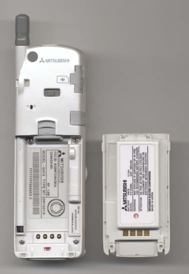
Click to zoom
Application Details
- Equipment Class
- PCE - PCS Licensed Transmitter held to ear
- Date of Grant
- Nov 21, 1999
- Application Purpose
- Original Equipment
- Date of Application
- Aug 18, 1999
- Frequency Range
- 1850.20000000 - 1909.80000000
- Company
- Mitsubishi Electric Corp
- Country
- United States
Documents & Files
Document Text
Text extracted from the exhibit documents filed with the FCC. Open a document above to read the original.
Users Manual
PCS 1900 MOBILE STATION HANDHELD PORTABLE TELEPHONE M4 Social (MT-239) User Operations Manual Part 1 Version 1.0 14 July, 1999 CONFIDENTIAL Mitsubishi Electric Page 2/102 . Table of Contents 1.INTRODUCTION ......................................................................................................................................... 5 1.1S ERVICES & FEATURES......................................................................................................................... 5 1.1.1Services............................................................................................................................................ 5 1.1.2Services: SMS and broadcast .......................................................................................................... 6 1.1.3Services: supplementary services .................................................................................................... 7 1.1.4Services: Memory related functions ................................................................................................ 8 1.1.5Advanced features............................................................................................................................ 9 1.1.6Other features ................................................................................................................................ 10 1.2P RODUCT KEYPAD.................................................................................................................................. 11 1.3K EYPAD USAGE...................................................................................................................................... 12 1.3.1Idle states....................................................................................................................................... 12 1.3.2Menus, lists and editors ................................................................................................................. 13 1.3.3Editors functions............................................................................................................................ 13 1.4A CTIONS MENUS CONTENTS.................................................................................................................... 14 1.5T ONES.................................................................................................................................................... 14 1.6B ACKLIGHT MANAGEMENT.................................................................................................................... 15 1.6.1Back lighting Behaviour with electrical connections .................................................................... 15 1.7B ATTERY CHARGING AND DISPLAY......................................................................................................... 16 1.7.1Charging and mobile on ................................................................................................................ 16 1.7.2Charging and mobile off................................................................................................................ 16 1.8L ED BEHAVIOUR AND CONNECTIONS...................................................................................................... 17 1.9R EADING THE IMEI.................................................................................................................................. 17 2.MOBILE SWITCHING ON AND OFF .................................................................................................... 18 2.1M OBILE SWITCH-ON BY THE USER......................................................................................................... 18 2.2M OBILE SWITCHING OFF BY THE USER.................................................................................................... 20 3.STAND-BY STATE DESCRIPTION ........................................................................................................ 21 3.1P RESENTATION....................................................................................................................................... 21 3.2I NFORMATION DISPLAY IN IDLE STATE.................................................................................................... 21 3.2.1Permanent display ......................................................................................................................... 21 3.2.2Additional display.......................................................................................................................... 21 3.2.3Information management in Idle screen ........................................................................................ 22 3.3S HORT-CUTS FROM IDLE WINDOW........................................................................................................... 26 3.3.1Quick ADN direct access ............................................................................................................... 26 3.3.2General menu access ..................................................................................................................... 26 3.3.3Direct Alert tones access ............................................................................................................... 26 3.3.4Keypad lock ................................................................................................................................... 26 3.3.5Speed dialling ................................................................................................................................ 26 3.3.6Last numbers dialled list................................................................................................................ 26 3.3.7Volumes control ............................................................................................................................. 26 3.3.8Programming the hotkey ..................................................................................…
Text truncated - open the document above for the full version.
Users Manual
PCS 1900 MOBILE STATION HANDHELD PORTABLE TELEPHONE M4 Social (MT-239) User Operations Manual Part 2 Version 1.0 14 July, 1999 CONFIDENTIAL Mitsubishi Electric Page 2/129 Table of Contents 8.USING THE PHONE BOOKS..................................................................................................................... 5 8.1G ENERAL ACCESS TO PHONE BOOKS........................................................................................................ 5 8.2R EADING PHONE BOOKS........................................................................................................................... 5 8.2.1Access .............................................................................................................................................. 5 8.2.2Reading phone books....................................................................................................................... 7 8.3W RITING IN PHONE BOOKS..................................................................................................................... 12 8.3.1Access ............................................................................................................................................ 12 8.3.2Operations ..................................................................................................................................... 12 8.4M EMORIES CAPACITY CONTROL............................................................................................................. 15 8.5O WN NUMBERS DISPLAY......................................................................................................................... 16 8.5.1Presentation................................................................................................................................... 16 8.5.2Example ......................................................................................................................................... 16 8.6U SING FIXED DIALLING.......................................................................................................................... 18 8.6.1Presentation................................................................................................................................... 18 8.6.2Reading the FDN file ..................................................................................................................... 18 8.6.3Entering data in the FDN file ........................................................................................................ 19 8.6.4Setting On/Off the fixed dialling mode .......................................................................................... 20 9.USING THE MESSAGING SYSTEM FACILITIES .............................................................................. 21 9.1M ESSAGES PRESENTATION..................................................................................................................... 21 9.2 RECEIVING MESSAGES............................................................................................................................. 21 9.2.1Setting the message alert mode...................................................................................................... 22 9.2.2Messages inbox management ........................................................................................................ 23 9.3P REPARING MESSAGE SENDING............................................................................................................... 34 9.3.1Message templates ......................................................................................................................... 34 9.4C OMPOSING MESSAGES.......................................................................................................................... 43 9.4.1Creating and sending new messages (several templates) .............................................................. 43 9.4.2Creating and sending new messages (no template) ....................................................................... 45 9.4.3Outbox consultation....................................................................................................................... 46 9.5R ECEIVING STATUS REPORTS FOR SENT MESSAGES................................................................................. 51 9.5.1General .......................................................................................................................................... 51 9.5.2Status Report Message display ...................................................................................................... 51 9.5.3User actions ................................................................................................................................... 51 9.5.4Status reports examples ................................................................................................................. 51 10.USING THE GSM SERVICES .............................................................................................................. 53 10.1N ETWORK SERVICES DEFINITION AND CATEGORIES............................................................................ 53 10.2U SING THE CALL DIVERTING SERVICE................................................................................................ 54 10.2.1Call diverting available options ................................................................................................ 54 10.2.2Call diverting always (CFU) management ................................................................................ 55 10.2.3"Forwarded-to" number entry ................................................................................................... 55 10.2.4Call diverting screen sequences ................................................................................................ 55 10.3U SING THE CALL WAITING SERVICE...............................................…
Text truncated - open the document above for the full version.
Attestation Statements
1. Description of General Information 1.1 Applicant {2.983(a)} Mitsubishi Electric Corporation Marunouchi 2 - Chome Chiyoda - Ku Tokyo 100, Japan Mailing Address: Mitsubishi Digital Electronics America, Inc. 1240 West Northwest Highway Palatine, IL 60067-1897 1.2 Manufacturer Mitsubishi Wireless Communications Inc. 3805 Crestwood Parkway, Suite 400 Duluth, GA 30096 1.3 Equipment {2.983(b)} Class I PCS 1900 Mobile Telephone Type: MT-239XG01A 1.4 Identification of the Equipment FCC ID: BGBMT239XG01A 1.5 Service 47 CFR 24 Subpart E Broadband PCS Personal Communications Service 1.6 Quantity Production {2.983(c)} Quantity production is planned.
Attestation Statements
MT-239 FCC ApplicationExhibit 3 – 4Page 1 of 2 FCC ID: BGBMT239XG01A 3. Certification {2.909} Certification of Measurement Data of Transceiver Type MT-239XG01A PCS 1900 Mobile Telephone I certify that the data contained in this technical data was collected under my supervision and at my request. To the best of my knowledge and belief, the facts set forth herein are true and correct. Norio Nishimura Manager Section-A Radio Terminal Engineering Department North America Radio Terminal Business department Mitsubishi Electric Corporation Mobile Communication Business Division I certify that the data contained in this technical data was measured and listed by me. To the best of my knowledge and belief, the facts set forth herein are true and correct. Keiichi Sadahiro Engineer Section-A Radio Terminal Engineering Department North America Radio Terminal Business department Mitsubishi Electric Corporation Mobile Communication Business Division MT-239 FCC ApplicationExhibit 3 – 4Page 2 of 2 FCC ID: BGBMT239XG01A 4. Statement of Qualification Name:Norio Nishimura Born:August 20, 1961 Education:College of Technology Experience:14 years Name:Keiichi Sadahiro Born:September 11, 1967 Education:College of Technology Experience: 9 years
Cover Letter(s)
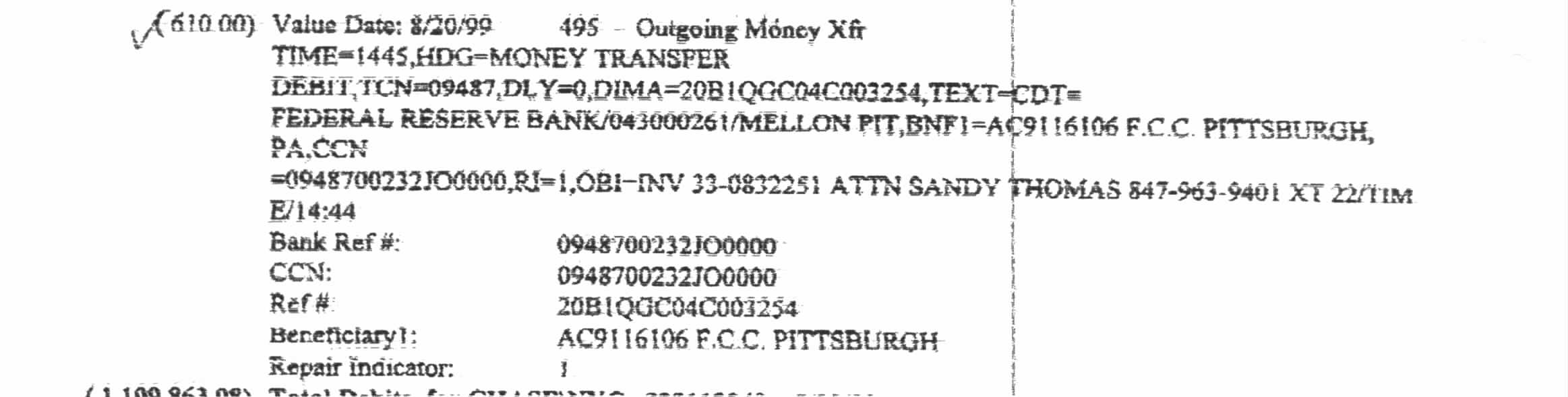
REQUEST FOR CONFIDENTIALITY CONTAINED WITHIN August 19, 1999 Federal Communications Commission Equipment Approval Service P. O. Box 358315 Pittsburgh, PA 15251-5315 Subject:Application for Cellular Mobile Telephone FCC ID: BGBMT239XG01A Gentlemen: We wish to submit our Application for Certification of the subject PCS Mobile Telephone. This equipment is a cellular handheld mobile telephone intended for operations under the Broadband Personal Communications Service governed by 47CFR24 Subpart E. The equipment also conforms to 47CFR2, 47CFR15, J-STD-007 and IEEE Std. C95.1-1992: IEEE Standard for Safety Levels with Respect to Human Exposure to Radio Frequency Electromagnetic Fields, 3 kHz to 300 GHz. Enclosed please find the following documentation: 1. Form 731 Applications for Certification (Fee Code EFT) and Confidentiality Request (Fee Code EBC), and FCC Form 159 “Remittance Advice”. 2. Wire Transfer in the amount of $610.00 3. Exhibits A) Exhibit 1 Description of General Information B) Exhibit 2 Technical Description C) Exhibit 3 Certification of Measurement Data D) Exhibit 4 Statement of Qualification E) Exhibit 5 Measurement Data, Including SAR Data F) Exhibit 6 Measurement Procedure G) Exhibit 7 Identification of Equipment H) Exhibit 8 Photographs I) Exhibit 9 Circuit Diagrams J) Exhibit 10 User’s Manual CONFIDENTIALITY REQUEST – Pursuant to 47CFR0.459 of the Commission’s Rules, we request that all information contained in Exhibit 2 and Exhibit 9 be withheld from public disclosure. This material is CONFIDENTIAL INFORMATION, and contains trade secrets and details that would not be typically available to the public. If you have any questions or require additional information, please contact me by telephone (847) 963-9401, Ext 22, Facsimile at (847) 963-9406 or by E-Mail at [email protected]. Sincerely, R. Gruhlke Director Regulatory Liaison Division RG/sst Cc:MWCI, Mr. Ted Sims G99A0813-3A
Cover Letter(s)
October 25, 1999 Mr. G. Czumak Engineer FCC Application Processing Branch Federal Communications Commission Equipment Approval Service P. O. Box 358315 Pittsburgh, PA 15251-5315 RE::Submitting Additional Information Regarding Cellular Telephone Transceiver FCC ID: BGBMT239XG01A 731 Confirmation No.: EA95200 Correspondence Ref. No.: 10221 Dear Mr. Czumak: In accordance with your e-mail dated October 16, 1999, we wish to submit additional information. 1. Field Strength / Maximum EIRP – The calculated theoretical EIRP using the Friis Transmission Formula is 2.173 Watts. However, this formula assumes a perfect isotropic radiator. We actually measured the radiated power of this device using the antenna substitution method at a 3- meter site. Please reference Exhibit 5, Sec. 5.2.2 for the data and calculation, and Exhibit 6, Sec. 6.1.2 for a description of the test method. The maximum radiated power measured using the antenna substitution method was 0.971W for a maximum field strength reading of 128.6dBuV/m. 2. Correct Emission Designator – We have always based the emission designator on the necessary bandwidth, not occupied bandwidth noted in test measurements. Also, we reviewed the FCC application of many other Cellular Telephone Transceivers, and found their emission designators are not based on measured occupied bandwidth data. Please reference 47CFR2.202. However, if the FCC’s policy regarding this has changed, please inform us, and we will revise the designator for this application and future applications. 3. Confidentiality Request – When we originally uploaded this FCC application, we noted which files should be considered “Confidential”. Pursuant to 47CFR0.459 of the Commission’s Rules, we request that the following information be withheld from public disclosure. This material is CONFIDENTIAL information, and contains trade secrets and details that would not be typically available to the public: FileFile DescriptionExhibit TypeExhibit MT239EX12Aoper.docTechnical DescriptionOperational Description2 MT239EX12BOC.docDescription of Oscillator and Synthesizer Circuits Operational Description2 MT239EX12C Sup.Lim.doc Suppression of Spurious Radiation and Limiting Power Operational Description2 MT239EX12DMod.docDescription of Modulation System Operational Description2 MT239EXC10ATune.docTune Up ProcedureParts Lists/Tune Up2 EXC5ASCHEM.docCircuit DiagramsSchematics9 4. Tissue Ingredients – As stated in the SAR report (2.5 Simulated Tissue), the solution does not contain sugar or salt for high frequency data (1.9GHz); alcohol (diethylengTykol Monobutylether) is used in the mixture. The approximate mixture to obtain the dielectric constant/conductivity of published values is as follows: Water, 56% Alcohol, 44% Density was approximately 996Kg/m 3 5. Correct Spurious Emission – Yes, you are correct. The spurious emission limit should be 82.2dBuV/m at 3-meters, not 84.4. If you have any questions or require additional information, please contact me. Sincerely, R. Gruhlke Director Regulatory Liaison Division RG/sst Cc:MWCI, Mr. Ted Sims Mr. S. Jung
External Photos
MT-239 FCC ApplicationExhibit 8 FCC ID: BGBMT239XG01A 8. Photographs of the Equipment {2.983(g)} Photograph 8.1 MT-2391G01A (Model 1 - Front View - Flip Closed - Antenna Down) MT-239 FCC ApplicationExhibit 8 FCC ID: BGBMT239XG01A Photograph 8.2 MT-2391G01A (Model 1 - Front View - Flip Closed - Antenna Up) MT-239 FCC ApplicationExhibit 8 FCC ID: BGBMT239XG01A Photograph 8.3 MT-2394G01A (Model 1 - Front View - Flip Open - Fixed Antenna) MT-239 FCC ApplicationExhibit 8 FCC ID: BGBMT239XG01A Photograph 8.4 MT-239XG01A (Back View with Battery) MT-239 FCC ApplicationExhibit 8 FCC ID: BGBMT239XG01A Photograph 8.5 MT-239XG01A (Back View with Battery Removed) MT-239 FCC ApplicationExhibit 8 FCC ID: BGBMT239XG01A Photograph 8.6 AC Adapter with Label
ID Label/Location Info
MT-239 FCC ApplicationExhibit 7 FCC ID: BGBMT239XG01A 7. Identification Plate {2.983(f)} 7.1 Identification Plate Drawing/Identification Plate Location Figure 7.1.1 Identification Plate Drawing/Identification Plate Location MITSUBISHI WIRELESS COMMUNICATIONS G410JBJXXXXXX ASSEMBLED IN USA SER. NO. FCC ID:BGBMT239XG01ACANADA NO: RF-1.0W MODEL - G410 TYPE MT-2391G01A TTTTTTFFSSSSSS C CTIA CTIA TTTTTTFFSSSSSS C TYPE MT-2391G01AMODEL-G410 RF-1.0W CANADA NO: FCC ID:BGBMT239XG01A 22.522.5 4040 ‚r ‚Q ^‚P WIRELESS COMMUNICATIONS MITSUBISHI G410JBJXXXXXX SER. NO. ASSEMBLED IN JAPAN SER. NO. 55 1616
Internal Photos
MT-239 FCC ApplicationExhibit 8 FCC ID: BGBMT239XG01A 8. Photographs of the Equipment {2.983(g)} Photograph 8.7 MT-239XG01A (Back Cover Removed) MT-239 FCC ApplicationExhibit 8 FCC ID: BGBMT239XG01A Photograph 8.8 MT-239XG01A (Front Cover Removed) MT-239 FCC ApplicationExhibit 8 FCC ID: BGBMT239XG01A Photograph 8.9 Front PWB with Shield MT-239 FCC ApplicationExhibit 8 FCC ID: BGBMT239XG01A Photograph 8.9 Front PWB with Shield Removed MT-239 FCC ApplicationExhibit 8 FCC ID: BGBMT239XG01A Photograph 8.10 Back PWB with Shields MT-239 FCC ApplicationExhibit 8 FCC ID: BGBMT239XG01A Photograph 8.11 Back PWB with Shield Removed MT-239 FCC ApplicationExhibit 8 FCC ID: BGBMT239XG01A Photograph 8.12 Front PWB without Shield MT-239 FCC ApplicationExhibit 8 FCC ID: BGBMT239XG01A Photograph 8.13 Back PWB
RF Exposure Info
3D-EMC Laboratory, Inc. Product Compliance SAR Test Report Product : Mitsubishi Model : N/A FCC ID :BGBMT239XG01A Reference no.:10037 3D-EMCLaboratory,Inc. for NEAR FIELD MEASUREMENTS 3D-EMC Laboratory, Inc. TABLE OF CONTENT 1.1 SAR TEST REPORT.............................................................................................................................................3 1.2 PRODUCT COMPLIANCE TEST REPORT..................................................................................................4 2.1 GUIDELINES.........................................................................................................................................................5 LOCATION OF TEST.......................................................................................................................................................5 2.2 MEASUREMENT SYSTEM SPECIFICATIONS.........................................................................................5 2.3 TEST DESCRIPTION.........................................................................................................................................6 2.4 PHANTOM............................................................................................................................................................6 2.5 SIMULATED TISSUE..........................................................................................................................................6 PREPARATION..............................................................................................................................................................7 2.6 MEASUREMENT OF ELECTRICAL CHARACTERISTICSOF SIMULATED TISSUE...................7 DESCRIPTION OF THE SLOTTED COAXIAL WAVEGUIDE...............................................................................................8 2.7 SYSTEM DESCRIPTION....................................................................................................................................9 2.8 DATA EXTRAPOLATION................................................................................................................................10 2.9INTERPOLATION AND GRAM AVERAGING..........................................................................................10 2.10 POWER MEASUREMENT.............................................................................................................................11 2.11 POSITIONING OF D.U.T................................................................................................................................11 3.1 DATA......................................................................................................................................................................13 ANTENNAOUT..........................................................................................................................................................__ TEST INFORMATION...................................................................................................................................................__ ATTENUATION VERSUS DEPTH SCAN........................................................................................................................__ AREA SCAN CONTOURPLOT.....................................................................................................................................__ 3D PLOT OF ABSORBED ENERGY.............................................................................................................................__ ANTENNAIN..............................................................................................................................................................__ TEST INFORMATION...................................................................................................................................................__ ATTENUATION VERSUS DEPTH SCAN........................................................................................................................__ AREA SCAN CONTOURPLOT.....................................................................................................................................__ 3D PLOT OF ABSORBED ENERGY.............................................................................................................................__ SIMULATEDTISSUE..................................................................................................................................................__ SIMULATED TISSUE TEST REPORT.......................................................................................................................__ 3D-EMC Laboratory, Inc. SAR Test Report To:Mitsubishi Date:07/16/99 Re:10037 Radio Information Radio Type:Cellular Phone Model Number:N/A Serial Number:PROT 4 Frequency Band(MHz)1900 Frequency Tested(MHz)1850 Nominal Output Power:(W) 1.000pk / av Antenna Type:½ Wave Antenna Position:In Signal Type:GSM Duty Cycle:8:1 Simulated Tissue Type of Tissue:brain Measured Dielectric Constant:40.1 Measured Conductivity:1.22 Conditions Robot:6 Axis Scan Type:SAR Measured Field:E Measured Power(W):0.099 (Compensated for Cable Loss) Phantom Type:head Phantom Position:left ear Room Temperature °C:24.5 Distance Antenna-Shell:18 mm Probe Probe Name:E3 Probe Orientation:- Probe Offset(mm):3.0 Sensor Factor:10.8 Conversion Factor:1.12 Calibration Date:05/27/99 Results Maximum Fields Location:X : 5Y : 5 Peak Voltage (mv):5.08 1cm Voltage (mv):2.09 SAR (averaged over 1 gram of tissue) W/kg: 0.37 (Antenna IN), 0.26 (Antenna OUT) Comments@ 1880 MHz, Power 0.102 W = SAR 0.36 (Antenna IN) and 0.28 (Antenna OUT) @ 1910 MHz, Power 0.102 W = SAR 0.31 (Antenna IN) and 0.27 (Antenna OUT) Insertion loss of adapter cable = 0.2 dB (Measured by manufacturer) 3D-EMC Laboratory, Inc. 4 Product Compliance Test Report Re:10037 Manufacturer:Mitsubishi Address:Japan Product Description:Cellular Phone Product Classific…
Text truncated - open the document above for the full version.
Test Report
MT-239 FCC ApplicationExhibit 6Page 1 of 7 FCC ID: BGBMT239XG01A 6. Measurement Procedures 6.1 Radio Frequency Power Output Measurement Procedure {2.985(a)} 6.1.1 Conducted Power Output Measurement Procedure Equipment Used:Hewlett Packard HP8922M GSM MS Test Set with HP83220E DCS/PCS MS Test Set KENWOOD PA18-6A Regulated DC Power Supply RF Insertion Loss: 0 dB (directly connected to equipment with a dedicated RF cable for the MS the measurements includes loss of the cable.) The following steps outline the procedure used to measure the RF power output from the mobile station. 1. Connect cable from RF connector on MS to RF IN/OUT of the HP83220E. 2. Apply 3.8Vdc to the MS. Power up MS. 3. Setup the MS for maximum output power (power level 0) with pseudo random data modulation. 4. Use HP8922M to obtain time mask and peak output power levels. 5. Repeat measurements for carrier frequencies at 1850.2 MHz, 1880.0 MHz, and 1909.8 MHz. Channels 512, 661, and 810 respectively (bottom, middle, and top of operational frequency range. 6. Repeat for power levels 7 (mid power level) and 15 (lowest power level). 7. For time mask plots put the MS into a simulated, plot out graphical representations of the rising, middle, and falling portions of the transmit burst. 8. Repeat for channels 512, 661, and 810 and for high and low power levels. 6.1.2 Radiated Power Output Measurement Procedure To measure radiated power (EIRP) using antenna substitution method, the EUT is placed on a support of non-metallic material, the height of which is 1 m above the ground plane. Measurements are made by the substitution method with the antenna having both horizontal and vertical polarizations and the turntable with the EUT is rotated. The highest level of radiation is noted at each measuring frequency. The EUT is replaced by a transmitting antenna supplied by a standard generator and having the same characteristics of the receiving antenna. For each measuring frequency the output level of the generator is adjusted in order to give the same reference indication on the measuring set. The level of available power of the generator, increased by the radiating antenna gain above the half-wave dipole, is taken as the level of the radiated power of the EUT at the considered frequency. MT-239 FCC ApplicationExhibit 6Page 2 of 7 FCC ID: BGBMT239XG01A 6.2 Occupied Bandwidth Measurement Procedure {2.989(h)} Equipment Used:Hewlett Packard HP8562E Spectrum Analyzer Hewlett Packard HP8753D Network Analyzer Hewlett Packard HP8498A 30dB Attenuator KENWOOD PA18-6A Regulated DC Power Supply RF Insertion Loss: 30.0 dB - attenuator and cabling The following steps outline the procedure used to measure the occupied bandwidth from the mobile station. 1. Determine the measurement bandwidth: 1% of the occupied bandwidth of 250 KHz corresponds to a resolution bandwidth of 2.5 KHz, for this test a resolution bandwidth of 3.0 KHz was used. 2. Outli…
Text truncated - open the document above for the full version.
Contact Information
Applicant
Richard Gruhlke(Principal Compliance Engineer)
Technical Specifications
| # | Rule Parts | Frequency Range | Power Output | Emission | Tolerance |
|---|---|---|---|---|---|
| 1 | 24E | 1.85 GHz - 1.91 GHz | 1 W | 248KGXW | 200.0000000000 Hz |
Other Applications from Mitsubishi Electric Corp

BGBCP-D90DW
Sep 23, 2015Digital Color Printer
Equipment Class
DXX - Part 15 Low Power Communication Device Transmitter
BGBCP-C60DW
Jan 22, 2014Digital Color Printer
Equipment Class
DXX - Part 15 Low Power Communication Device Transmitter
BGBCP-D70DW
Jul 22, 2010Digital Color Printer
Equipment Class
DXX - Part 15 Low Power Communication Device Transmitter
BGBMT0WM07G0R25
Sep 02, 2007GSM/WCDMA Mobile Phone with NFC Function
Equipment Class
DXX - Part 15 Low Power Communication Device Transmitter
BGBX1T502SKE11A01
Aug 31, 2005Smart Keyless System (ECU)
Equipment Class
CYY - Communications Receiver used w/Pt 15 Transmitter