BGBMT254XFOR6A
Mitsubishi Electric Corp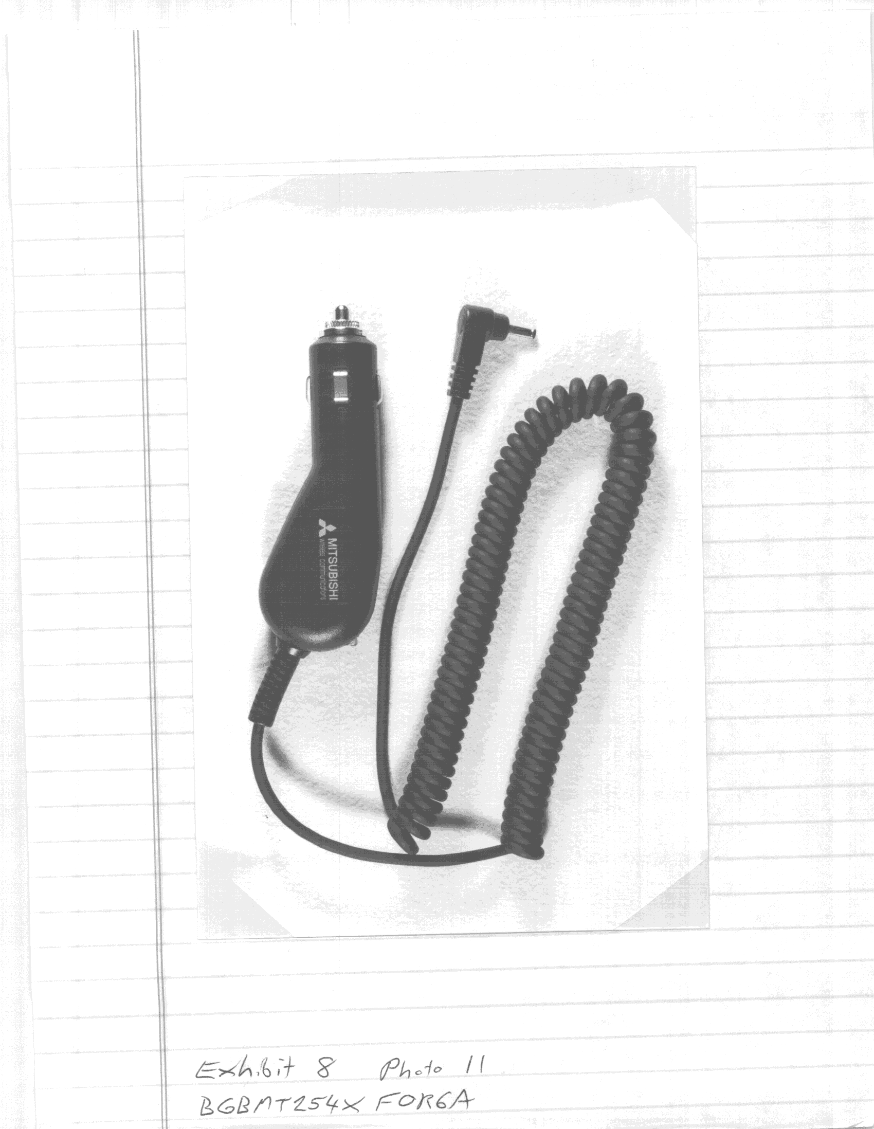
Click to zoom
Application Details
- Equipment Class
- PCE - PCS Licensed Transmitter held to ear
- Date of Grant
- Nov 21, 1999
- Application Purpose
- Original Equipment
- Date of Application
- Aug 02, 1999
- Frequency Range
- 1850.04000000 - 1909.92000000
- Company
- Mitsubishi Electric Corp
- Country
- United States
Documents & Files
Document Text
Text extracted from the exhibit documents filed with the FCC. Open a document above to read the original.
Cover Letter(s)
October 28, 1999 Mr. G. Czumak Engineer FCC Application Processing Branch Federal Communications Commission Equipment Approval Service P. O. Box 358315 Pittsburgh, PA 15251-5315 RE::Submitting Additional Information Regarding Cellular Telephone Transceiver FCC ID: BGBMT254XFOR6A 731 Confirmation No.: EA95160 Correspondence Ref. No.: 10215 Dear Mr. Czumak: We wish to reply to your e-mail dated October 15, 1999 as follows: 1. Line Entry for CDPD Browser for Internet Access – The CDPD Function uses GMSK modulation. Test Data is provided with this application for this mode of operation. Therefore, we do not believe an additional line entry is required. Our MT151 Phone (FCC ID: BGBMT151XFOR6A) also uses the same modulation for the CDPD Function and The Commission accepted it as “28K8FXW”. Please confirm if we should change this designation for this application, and future applications. If you have any questions or require additional information, please contact me. Sincerely, R. Gruhlke Director Regulatory Liaison Division RG/sst Cc:MWCI, Mr. Ted Sims Mr. S. Jung
Cover Letter(s)
October 28, 1999 Mr. G. Czumak Engineer FCC Application Processing Branch Federal Communications Commission Equipment Approval Service P. O. Box 358315 Pittsburgh, PA 15251-5315 RE::Submitting Additional Information Regarding Cellular Telephone Transceiver FCC ID: BGBMT254XFOR6A 731 Confirmation No.: EA95160 Correspondence Ref. No.: 10214 Dear Mr. Czumak: We wish to reply to your e-mail dated October 15, 1999 as follows: 1. Measurement Data Supporting ERP/EIRP Values –The EIRP and ERP values have been calculated from measured antenna gain and measured conducted power as follows. The peak antenna gain values from measured data are -1.84dBd in 800MHz and +0.45dB in 1900MHz. 1) So, in the case of 800MHz "A800" Power = 0.4W = 26.02dBm, so A800 ERP = 24.18dBm, which is 0.26W ERP "D800" Power = 0.48W = 26.8dBm, so D800 ERP = 24.9dBm, which is 0.31W ERP 2) In the case of 1900MHz, "D1900" Power = 0.38W = 25.8dBm, so D1900 EIRP = 28.24dBm, which is 0.67W EIRP 2. Correct Emission Designators – In accordance with 47CFR2.202, the emission designator is not determined by occupied bandwidth test data. It is determined by necessary bandwidth. We have reviewed FCC filings by several other competitors, and found they also specify emission designators based on necessary bandwidth, not actual measurement data. Please confirm if this is a new policy by the FCC, and we will revise the emission designator for this application, and all future applications. 3. Confirmation of PCS and Cellular TDMA Formats - The phone operates in three modes AMPS, CDPD, and TDMA which have been measured separately, where applicable. 1) AMPS mode Emissions designator is 40K0F8W and 40K0F1D corresponding to the FM and FSK used in AMPS. This mode only operates in the cellular (800) band. The power rating for this mode is listed in our document as “A800” under section 2.3 2) CDPD mode Emissions designator is 28K8FXW, corresponding to the GMSK modulation used in standard CDPD. This mode only operates in the cellular (800) band. The power rating for this mode is listed in our document as “A800” under section 2.3. We have taken 28K8FXW to be the accepted emission designator for GMSK used on CDPD, based on previous precedent, notably Mitsubishi BGBMT151XFOR6A, which has the same emission characteristics. However, we will use whatever designator the Commission finds appropriate, of course. 3) TDMA mode The emissions designator is 40K0GXW, corresponding to the pi/4QPSK used in the TDMA(IS- 136) standard. This mode operates in the cellular (800) and PCS (1900) MHz band. The power ratings for this mode are listed in our submission document as “D800” and “D1900”, respectively, under section 2.3. We have taken 40K0GXW to be the accepted emission designator for IS-136 pi/4QPSK based on previous precedent, notably Ericsson AXATR-363-A2, and Mitsubishi BGBMT253XFOR6A. We believe the designator should be the same as these. However, we will use whatever designator the Commission finds appropriate. 4. Actual Tuning Range of PCS Emissions – Low Channel 1850.04MHz, and High Channel 1909.92MHz. 5. Clarification of Device Output Power Measurements in AMPS and TDMA Modes of Operation - The first set of tolerances, i.e., 26.0 dBm +3.8/-2.2 dB for the AMPS mode 26.8 dBm +3.0/-3.0 dB for cellular TDMA 25.8 dBm +4.0/-2.0 dB for PCS, are the tolerances according to the EIA IS-137. We included them basically for reference. In no way do we mean to say that the unit is capable of operating within this range. However, for the purposes of this application please note the following tolerances, based on the specified power adjustment procedures: A. Amps Mode – 26..0dBm +/- 0.5dB B. Cellular TDMA – 26.8dBm +/- 1dB C. PCS – 25.8dBm +/- 1dB 6. Composition of Tissue Material Ingredients for SAR Measurements Measurement Frequency*Tissue Ingredients 835MhzWater (44.3%) Sugar (54.7%) Salt (0.9%) HEC (0.1%) 1900MhzDistilled Water (56%) Deithyl Englykol (44%) *% by weight 7. SAR Data Supporting Operation Using Accessories – Please reference new SAR Data uploaded under Attachment “MT254withaccessory”. 8. Antenna Configurations – There is only one antenna, a non-retractable type, used for this device. 9. SAR Data Supporting Battery Options – Please reference new SAR Data uploaded under Attachment “MT254withaccessory”. The SAR limit is not exceeded with any of the battery options. If you have any questions or require additional information, please contact me. Sincerely, R. Gruhlke Director Regulatory Liaison Division RG/sst Cc:MWCI, Mr. Ted Sims Mr. S. Jung
Cover Letter(s)
November 15, 1999 Mr. G. Czumak Engineer FCC Application Processing Branch Federal Communications Commission Equipment Approval Service P. O. Box 358315 Pittsburgh, PA 15251-5315 RE::Submitting Additional Information Regarding Cellular Telephone Transceiver FCC ID: BGBMT254XFOR6A 731 Confirmation No.: EA95160 Correspondence Ref. No.: 10574 Dear Mr. Czumak: In accordance with your e-mail dated November 8, 1999, we wish to upload additional information for the subject application: 1. Worst Case Body-Worn SAR for Normal Use – We have conducted additional SAR Testing to clarify and determine appropriate distance needed for satisfying body-worn SAR compliance for the belt-clip. We have uploaded this data for your reference. 2. User’s Manual Warning Statement for RF Exposure Compliance – We have added a “Warning Statement” to the first page of the User’s Manual, to specify conditions of use, for compliance with FCC RF Exposure Limits. We have uploaded a copy of this text. 3. Corrected Emission Designators – We uploaded a corrected Form 731. Also, we uploaded a corrected Technical Description (47CFR2.983). If you have additional questions or require additional information, please contact me. Sincerely, R. Gruhlke Director Regulatory Liaison Division RG/sst Cc:MWCI, Mr. Ted Sims
Operational Description
Exibit 2-1 2. Technical Description {2.983(d)} 2.1 Type of Emission {2.983(d)(1)} 800MHz:40K0F8W, 40K0F1D, 27K8DXW, 28K8GXW 1900MHz:27K8DXW 2.2 Frequency Range {2.983(d)(2)} 824 MHz to 849 MHz, 1850 MHz to 1910 MHz 2.3 Power Rating {2.983(d)(3-5)} A800MHzD800MHz1900MHz (1) Input Power for Final Amplifier4 dBm4 dBm0 dBm (2) Input Voltage for Final Amplifier 4.8 V4.8 V4.8 V (3) Input Current for Final Amplifier 650 mA340 mA400 mA (4) Rated Output Power0.26 W ERP0.31 W ERP 0.67W EIRP Based on antenna gain values (from measurements) of -1.84dBd 800MHz band +0.45dBd1900MHz band 2.4 Functions of All Active Devices {2.983(d)(6)} Table 2.4-1 Active Devices of Transceiver Unit Symbol Part Number Manufacture Function IC 101 TA75S393F-TE85R TOSHIBA IC IC 106 RN5RG33AA-TR RICOH IC IC 107 TK11233BMCL TOKO IC IC 108 TK11333BMCL TOKO IC IC 109 RN5RL32AA-TR RICOH IC IC 110 RN5VD18CA-TR RICOH IC IC 111 TK11233BMCL TOKO IC IC 112 TK11233BMCL TOKO IC IC 180 H8S_2655 HITACHI IC IC 181 FX589D5 CML IC IC 182 TC55257 IC IC 183 TC7W08FU-TE12L TOSHIBA IC IC 185 TA75S01F-TE85R TOSHIBA IC IC 186 TA75S01F-TE85R TOSHIBA IC IC 201 PCI3601 PRAIRIECOMM IC IC 202 PCI3602 PRAIRIECOMM IC IC 203 TE28160B3T IC IC 204 TC55040FT IC Exibit 2-2
RF Exposure Info
3D-EMC Laboratory, Inc. Positioning of D.U.T. The surface of the D.U.T. is always in parallel with the phantoms shell and accessories(belt-clip and head-set) are equipped as shown below. 3D-EMC Laboratory, Inc. 3D-EMC Laboratory, Inc. Index of the measurements The following results of measurement are ordered as listed below. D.U.T with low capacity battery A800 mode @ low frequency(SAR:0.67) @ middle frequency(0.60) @ high frequency(0.65) D800 mode @ low frequency(0.23) @ middle frequency(0.21) @ high frequency(0.22) D1900 mode @ low frequency(0.08) @ middle frequency(0.11) @ high frequency(0.09) D.U.T. with high capacity battery A800 mode @ low frequency(0.91) @ middle frequency(0.86) @ high frequency(0.91) D800 mode @ low frequency(0.36) @ middle frequency(0.31) @ high frequency(0.33) D1900 mode @ low frequency(0.08) @ middle frequency(0.11) @ high frequency(0.09) D.U.T. with vibrating battery A800 mode @ high frequency only(0.84) Electrical characteristic of Simulated tissue Muscle tissue @ 835 MHz Muscle tissue @ 1900 MHz 3D-EMC Laboratory, Inc. Date Time Manufacturer Model Number Serial Number FCC ID Number Simulated Tissue Probe Offset (mm) Sensor Factor (mV) Conversion Factor Calibrated Date Amplifier Setting : Location of Maximum Field : Measured Values (mV) : Test Frequency (MHz) Nominal Output Power (W) Antenna Type Signal Dielectric Constant Conductivity Antenna Position Measured Power (W) (conducted) Cable Insertion Loss (dB) Compensated Power (W) Test Information Product Phantom Probe Peak Voltage (mV)1 Cm Voltage (mV)SAR (W/Kg) : 10/26/99 : 10:50:15 AM : Cellular Phone : Mitsubishi : MT-254 : 00001 : BGBMT254XFOR6A : Waist : Muscle : E : 3.0 : 10.8 : 0.72 : 3/24/99 Channel 1 : 0.0045 Channel 2 : 0.0039 Channel 3 : 0.0031 X = 25 Y = -70 11.09 6.63 4.70 3.38 2.42 1.68 1.10 0.67 0.32 0.13 0.04 : 14.38: 5.74: 0.67 : SAR : 825 : 0.6 : 1/4 Wave : CW : 54.0 : 1.09 : FIX : 0.378 : 0.6 : 0.434 3D-EMC Laboratory, Inc. 1.37 2.74 4.11 5.48 6.85 8.22 9.59 3D-EMC Laboratory, Inc. 1.37 2.74 4.11 5.48 6.85 8.22 9.59 3D-EMC Laboratory, Inc. -10010203040 X Axis (mm) 0 -10 -20 -30 -40 -50 -60 -70 -80 Y Axis (mm) 1.37 2.74 4.11 5.48 6.85 8.22 9.59 3D-EMC Laboratory, Inc. 1015202530 X Axis (mm) -50 -55 -60 -65 -70 Y Axis (mm) 1.37 2.74 4.11 5.48 6.85 8.22 9.59 3D-EMC Laboratory, Inc. 0.00 0.10 0.19 0.29 0.38 0.48 0.57 0.67 051015202530 Depth (mm) 3D-EMC Laboratory, Inc. Date Time Manufacturer Model Number Serial Number FCC ID Number Simulated Tissue Probe Offset (mm) Sensor Factor (mV) Conversion Factor Calibrated Date Amplifier Setting : Location of Maximum Field : Measured Values (mV) : Test Frequency (MHz) Nominal Output Power (W) Antenna Type Signal Dielectric Constant Conductivity Antenna Position Measured Power (W) (conducted) Cable Insertion Loss (dB) Compensated Power (W) Test Information Product Phantom Probe Peak Voltage (mV)1 Cm Voltage (mV)SAR (W/Kg) : 10/26/99 : 11:06:29 AM : Cellular Phone : Mitsubishi : MT-254 : 00001 : BGBMT254XFOR6A : Waist : Muscle : E : 3.0 : 10.8 : 0.72 : 3/24/99 Channel 1 : 0.0045 Channel 2 : 0.0039 Channel 3 : 0.0031 X = 25 Y = -70 10.03 5.90 4.23 2.94 2.13 1.42 0.87 0.52 0.25 0.10 0.02 : 13.03: 5.20: 0.60 : SAR : 837 : 0.6 : 1/4 Wave : CW : 54.0 : 1.09 : FIX : 0.381 : 0.6 : 0.437 3D-EMC Laboratory, Inc. 1.29 2.58 3.87 5.16 6.45 7.74 9.03 3D-EMC Laboratory, Inc. 1.29 2.58 3.87 5.16 6.45 7.74 9.03 3D-EMC Laboratory, Inc. -10010203040 X Axis (mm) 0 -10 -20 -30 -40 -50 -60 -70 -80 Y Axis (mm) 1.29 2.58 3.87 5.16 6.45 7.74 9.03 3D-EMC Laboratory, Inc. 1015202530 X Axis (mm) -60 -65 -70 -75 -80 Y Axis (mm) 1.29 2.58 3.87 5.16 6.45 7.74 9.03 3D-EMC Laboratory, Inc. 0.00 0.09 0.17 0.26 0.34 0.43 0.52 0.60 051015202530 Depth (mm) 3D-EMC Laboratory, Inc. Date Time Manufacturer Model Number Serial Number FCC ID Number Simulated Tissue Probe Offset (mm) Sensor Factor (mV) Conversion Factor Calibrated Date Amplifier Setting : Location of Maximum Field : Measured Values (mV) : Test Frequency (MHz) Nominal Output Power (W) Antenna Type Signal Dielectric Constant Conductivity Antenna Position Measured Power (W) (conducted) Cable Insertion Loss (dB) Compensated Power (W) Test Information Product Phantom Probe Peak Voltage (mV)1 Cm Voltage (mV)SAR (W/Kg) : 10/26/99 : 11:24:36 AM : Cellular Phone : Mitsubishi : MT-254 : 00001 : BGBMT254XFOR6A : Waist : Muscle : E : 3.0 : 10.8 : 0.72 : 3/24/99 Channel 1 : 0.0045 Channel 2 : 0.0039 Channel 3 : 0.0031 X = 25 Y = -75 10.72 6.21 4.33 3.05 2.10 1.42 0.89 0.48 0.21 0.08 0.00 : 14.10: 5.39: 0.65 : SAR : 849 : 0.6 : 1/4 Wave : CW : 54.0 : 1.09 : FIX : 0.377 : 0.6 : 0.433 3D-EMC Laboratory, Inc. 1.35 2.70 4.05 5.40 6.75 8.10 9.45 3D-EMC Laboratory, Inc. 1.35 2.70 4.05 5.40 6.75 8.10 9.45 3D-EMC Laboratory, Inc. -10010203040 X Axis (mm) 0 -10 -20 -30 -40 -50 -60 -70 -80 Y Axis (mm) 1.35 2.70 4.05 5.40 6.75 8.10 9.45 3D-EMC Laboratory, Inc. 1015202530 X Axis (mm) -60 -65 -70 -75 -80 Y Axis (mm) 1.35 2.70 4.05 5.40 6.75 8.10 9.45 3D-EMC Laboratory, Inc. 0.00 0.09 0.18 0.28 0.37 0.46 0.55 0.65 051015202530 Depth (mm) 3D-EMC Laboratory, Inc. Date Time Manufacturer Model Number Serial Number FCC ID Number Simulated Tissue Probe Offset (mm) Sensor Factor (mV) Conversion Factor Calibrated Date Amplifier Setting : Location of Maximum Field : Measured Values (mV) : Test Frequency (MHz) Nominal Output Power (W) Antenna Type Signal Dielectric Constant Conductivity Antenna Position Measured Power (W) (conducted) Cable Insertion Loss (dB) Compensated Power (W) Test Information Product Phantom Probe Peak Voltage (mV)1 Cm Voltage (mV)SAR (W/Kg) : 10/26/99 : 9:59:25 AM : Cellular Phone : Mitsubishi : MT-254 : 00001 : BGBMT254XFOR6A : Waist : Muscle : E : 3.0 : 10.8 : 0.72 : 3/24/99 Channel 1 : 0.0045 Channel 2 : 0.0039 Channel 3 : 0.0031 X = 25 Y = -75 3.76 2.05 1.34 0.79 0.43 0.16 0.06 0.00 0.00 0.00 0.00 : 5.14: 1.89: 0.23 : SAR : 825 : 0.6 : 1/4 Wave : TDMA : 54.0 : 1.09 : FIX : 0.145 : 0.6 : 0.166 3D-EMC Laboratory, Inc. 0.49 0.98 1.47 1.96 2.45 …
Text truncated - open the document above for the full version.
RF Exposure Info
3D-EMC Laboratory, Inc. Positioning of the radio The surface of the radio is always in parallel with the phantoms shell and accessories(belt-clip and head-set) are equipped as shown below. - With High Capacity Battery 3D-EMC Laboratory, Inc. - With Low Capacity Battery 3D-EMC Laboratory, Inc. 3D-EMC Laboratory, Inc. Index of the measurements The following results of measurement are ordered as listed below. Radio with High capacity battery A800 mode @ low frequency(SAR:1.00) @ middle frequency(0.97) @ high frequency(1.03) D800 mode @ low frequency(0.41) @ middle frequency(0.36) @ high frequency(0.37) D1900 mode @ low frequency(0.11) @ middle frequency(0.11) @ high frequency(0.10) Radio with Low capacity battery A800 mode @ high frequency(0.97) Electrical characteristic of Simulated tissue Muscle tissue @ 835 MHz Muscle tissue @ 1900 MHz 3D-EMC Laboratory, Inc. Date Time Manufacturer Model Number Serial Number FCC ID Number Simulated Tissue Probe Offset (mm) Sensor Factor (mV) Conversion Factor Calibrated Date Amplifier Setting : Location of Maximum Field : Measured Values (mV) : Test Frequency (MHz) Nominal Output Power (W) Antenna Type Signal Dielectric Constant Conductivity Antenna Position Measured Power (W) (conducted) Cable Insertion Loss (dB) Compensated Power (W) Test Information Product Phantom Probe Peak Voltage (mV)1 Cm Voltage (mV)SAR (W/Kg) : 11/10/99 : 11:36:22 AM : Cellular Phone : Mitsubishi : MT-254 : 00001 : BGBMT254XFOR6A : Waist : Muscle : E : 3.0 : 10.8 : 0.72 : 3/24/99 Channel 1 : 0.0045 Channel 2 : 0.0039 Channel 3 : 0.0031 X = 25 Y = -65 16.40 10.41 6.92 4.56 2.85 1.68 1.13 0.71 0.40 0.18 0.03 : 21.24: 9.03: 1.00 : SAR : 825 : 0.6 : 1/4 Wave : CW : 49.1 : 1.15 : FIX : 0.378 : 0.6 : 0.434 3D-EMC Laboratory, Inc. 1.99 3.98 5.97 7.96 9.95 11.94 13.93 3D-EMC Laboratory, Inc. 1.99 3.98 5.97 7.96 9.95 11.94 13.93 3D-EMC Laboratory, Inc. -10010203040 X Axis (mm) 0 -10 -20 -30 -40 -50 -60 -70 -80 Y Axis (mm) 1.99 3.98 5.97 7.96 9.95 11.94 13.93 3D-EMC Laboratory, Inc. 1015202530 X Axis (mm) -50 -55 -60 -65 -70 Y Axis (mm) 1.99 3.98 5.97 7.96 9.95 11.94 13.93 3D-EMC Laboratory, Inc. 0.00 0.14 0.29 0.43 0.57 0.72 0.86 1.00 051015202530 Depth (mm) 3D-EMC Laboratory, Inc. Date Time Manufacturer Model Number Serial Number FCC ID Number Simulated Tissue Probe Offset (mm) Sensor Factor (mV) Conversion Factor Calibrated Date Amplifier Setting : Location of Maximum Field : Measured Values (mV) : Test Frequency (MHz) Nominal Output Power (W) Antenna Type Signal Dielectric Constant Conductivity Antenna Position Measured Power (W) (conducted) Cable Insertion Loss (dB) Compensated Power (W) Test Information Product Phantom Probe Peak Voltage (mV)1 Cm Voltage (mV)SAR (W/Kg) : 11/10/99 : 12:47:01 PM : Cellular Phone : Mitsubishi : MT-254 : 00001 : BGBMT254XFOR6A : Waist : Muscle : E : 3.0 : 10.8 : 0.72 : 3/24/99 Channel 1 : 0.0045 Channel 2 : 0.0039 Channel 3 : 0.0031 X = 20 Y = -60 16.09 10.63 7.39 5.21 3.67 2.53 1.70 1.08 0.62 0.29 0.07 : 20.33: 9.12: 0.97 : SAR : 836 : 0.6 : 1/4 Wave : CW : 49.1 : 1.15 : FIX : 0.370 : 0.6 : 0.425 3D-EMC Laboratory, Inc. 2.06 4.12 6.18 8.24 10.30 12.36 14.42 3D-EMC Laboratory, Inc. 2.06 4.12 6.18 8.24 10.30 12.36 14.42 3D-EMC Laboratory, Inc. -10010203040 X Axis (mm) 0 -10 -20 -30 -40 -50 -60 -70 -80 Y Axis (mm) 2.06 4.12 6.18 8.24 10.30 12.36 14.42 3D-EMC Laboratory, Inc. 1015202530 X Axis (mm) -60 -65 -70 -75 -80 Y Axis (mm) 2.06 4.12 6.18 8.24 10.30 12.36 14.42 3D-EMC Laboratory, Inc. 0.00 0.14 0.28 0.42 0.56 0.70 0.84 0.97 051015202530 Depth (mm) 3D-EMC Laboratory, Inc. Date Time Manufacturer Model Number Serial Number FCC ID Number Simulated Tissue Probe Offset (mm) Sensor Factor (mV) Conversion Factor Calibrated Date Amplifier Setting : Location of Maximum Field : Measured Values (mV) : Test Frequency (MHz) Nominal Output Power (W) Antenna Type Signal Dielectric Constant Conductivity Antenna Position Measured Power (W) (conducted) Cable Insertion Loss (dB) Compensated Power (W) Test Information Product Phantom Probe Peak Voltage (mV)1 Cm Voltage (mV)SAR (W/Kg) : 11/10/99 : 1:36:47 PM : Cellular Phone : Mitsubishi : MT-254 : 00001 : BGBMT254XFOR6A : Waist : Muscle : E : 3.0 : 10.8 : 0.72 : 3/24/99 Channel 1 : 0.0045 Channel 2 : 0.0039 Channel 3 : 0.0031 X = 20 Y = -65 17.04 11.10 7.55 5.21 3.61 2.45 1.61 0.99 0.55 0.21 0.03 : 21.76: 9.42: 1.03 : SAR : 849 : 0.6 : 1/4 Wave : CW : 49.1 : 1.15 : FIX : 0.377 : 0.6 : 0.433 3D-EMC Laboratory, Inc. 2.15 4.30 6.45 8.60 10.75 12.90 15.05 3D-EMC Laboratory, Inc. 2.15 4.30 6.45 8.60 10.75 12.90 15.05 3D-EMC Laboratory, Inc. -10010203040 X Axis (mm) 0 -10 -20 -30 -40 -50 -60 -70 -80 Y Axis (mm) 2.15 4.30 6.45 8.60 10.75 12.90 15.05 3D-EMC Laboratory, Inc. 1015202530 X Axis (mm) -50 -55 -60 -65 -70 Y Axis (mm) 2.15 4.30 6.45 8.60 10.75 12.90 15.05 3D-EMC Laboratory, Inc. 0.00 0.15 0.30 0.44 0.59 0.74 0.89 1.03 051015202530 Depth (mm) 3D-EMC Laboratory, Inc. Date Time Manufacturer Model Number Serial Number FCC ID Number Simulated Tissue Probe Offset (mm) Sensor Factor (mV) Conversion Factor Calibrated Date Amplifier Setting : Location of Maximum Field : Measured Values (mV) : Test Frequency (MHz) Nominal Output Power (W) Antenna Type Signal Dielectric Constant Conductivity Antenna Position Measured Power (W) (conducted) Cable Insertion Loss (dB) Compensated Power (W) Test Information Product Phantom Probe Peak Voltage (mV)1 Cm Voltage (mV)SAR (W/Kg) : 11/10/99 : 2:12:38 PM : Cellular Phone : Mitsubishi : MT-254 : 00001 : BGBMT254XFOR6A : Waist : Muscle : E : 3.0 : 10.8 : 0.72 : 3/24/99 Channel 1 : 0.0045 Channel 2 : 0.0039 Channel 3 : 0.0031 X = 20 Y = -65 6.76 4.08 2.80 1.80 1.11 0.68 0.29 0.07 0.00 0.00 0.00 : 8.81: 3.71: 0.41 : SAR : 825 : 0.6 : 1/4 Wave : TDMA : 49.1 : 1.15 : FIX : 0.147 : 0.6 : 0.169 3D-EMC Laboratory, Inc. 0.84 1.68 2.52 3.36 4.20 5.04 5.88 3D-EMC Laboratory, Inc. 0.84 1.68 2.52 3.36 4.20 5.04 5.88 3D-EMC Laboratory, Inc. -10010203040 X Axis (mm) 0 -10 -20 -30 -40 -50 -60 -70 -80 Y Axis (…
Text truncated - open the document above for the full version.
Contact Information
Applicant
Richard Gruhlke(Principal Compliance Engineer)
Technical Specifications
| # | Rule Parts | Frequency Range | Power Output | Emission | Tolerance |
|---|---|---|---|---|---|
| 5 | 24E | 1.85 GHz - 1.91 GHz | 670.00 mW | 27K8DXW | 200 Hz |
Other Applications from Mitsubishi Electric Corp

BGBCP-D90DW
Sep 23, 2015Digital Color Printer
Equipment Class
DXX - Part 15 Low Power Communication Device Transmitter
BGBCP-C60DW
Jan 22, 2014Digital Color Printer
Equipment Class
DXX - Part 15 Low Power Communication Device Transmitter
BGBCP-D70DW
Jul 22, 2010Digital Color Printer
Equipment Class
DXX - Part 15 Low Power Communication Device Transmitter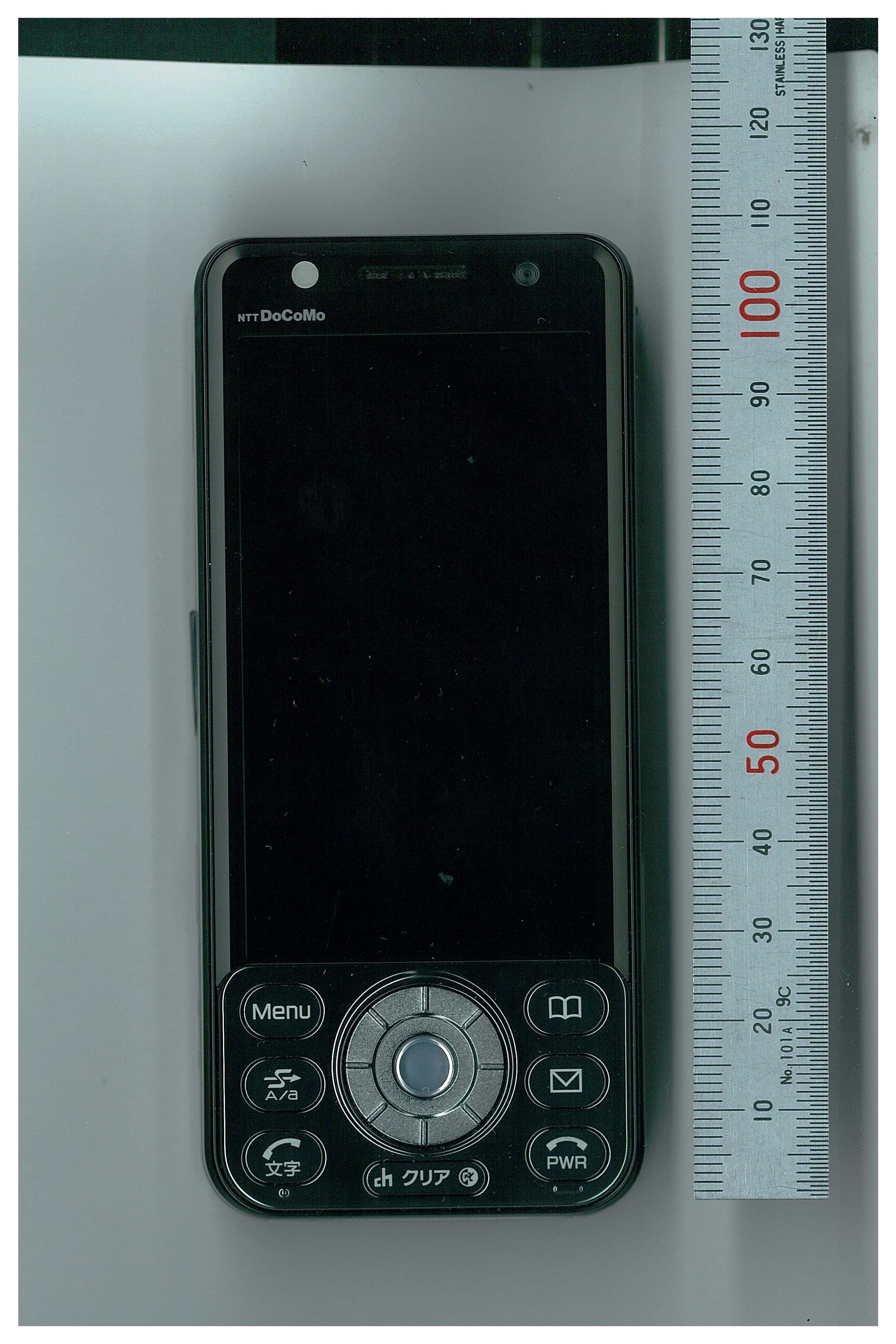
BGBMT0WM07G0R25
Sep 02, 2007GSM/WCDMA Mobile Phone with NFC Function
Equipment Class
DXX - Part 15 Low Power Communication Device Transmitter
BGBX1T502SKE11A01
Aug 31, 2005Smart Keyless System (ECU)
Equipment Class
CYY - Communications Receiver used w/Pt 15 Transmitter