BGBR-9000RSRS-232C Interface Board
Mitsubishi Electric Corp
Click to zoom
Application Details
- Equipment Class
- JBP - Part 15 Class B Computing Device Peripheral
- Date of Grant
- Jul 10, 2000
- Application Purpose
- Original Equipment
- Date of Application
- Jun 19, 2000
- Equipment Note
- RS-232C Interface Board
- Company
- Mitsubishi Electric Corp
- Country
- United States
Documents & Files
Document Text
Text extracted from the exhibit documents filed with the FCC. Open a document above to read the original.
Users Manual
INSTALL RS-232C INTERFACE BOARD ACCESSORIES : screw x 3 , Installation manual NOTE : • Voltage is supplied to some parts even when the POWER switch is turned off. To prevent electric shocks, be sure to turn off the VCR and unplug the power cord when installing the RS-232C interface PCB. • Read the warnings stamped or labeled in various locations on the VCR and its parts. 1. Remove the two screws securing the cover plate. ( Need not remove the top cover.) 2. To remove the cover plate, slide it to the left side and then pull it towards you. 3. Remove the cable from the cover plate. 4. Connect the cable terminal on the VCR(PCB) to the connector RE on the RS-232C PCB. 5. Insert the RS-232C PCB into the rear of VCR, as shown. 6. Slide the RS-232C PCB in the direction of the arrow. 7. On the rear of VCR, tighten the three screws that secure the RS- 232C PCB in place. For US only NOTE: FCC ID:BGBR-9000RS This device complies with part 15 of the FCC Rules. Operation is subject to the following two conditions: (1) This device may not cause harmful interference, and (2) this device must accept any interference received including interference that may cuase undesired operation. NOTE: This equipment has been tested and found to comply with the limita for a Class B digital device, pursuant to Part 15 of the FCC Rules. These limits are designed to provide reasonable protection against harmful interference in a residential installation. This equipment generates, uses, and can radiate radio frequency energy and, if not installed and used in accordance with the in- structions, may cause harmful interference to radio communications. However, there is no guarantee that interference will not occur in a particular installation. If this equipment does cause harmful interference to radio or television re- ception, which can be determined by turning the equipment off and on, the use is encouraged to try to correct the interference by one or more of the following measures: - Raorient or relocate the receiving antenna. - Increase the separation between the equipment and receiver. - Connect the equipment to an outlet on a circuit different from that to which the receiver is connected. - Consult the dealer or an experienced radio/TV technician for help. Changes or modifications not expressly approved by the party responsible for compliance could void the user’s authority to operate the equipment. For CANADA only INFORMATION THIS CLASS B DIGITAL APPARATUS COMPLIES WITH CANADIAN ICES- 003. INFORMATION CET APPAREIL NUMÉRIQUE DE LA CLASSE B EST CONFORME À LA NORME NMB-003 DU CANADA.
External Photos
R-R9000RS COMPONENT SIDE FCC ID:BGBR-9000RS R-R9000RS COPPER SIDE FCC ID:BGBR-9000RS
Operational Description
Product Specification Sheet R-9000RS MITSUBISHI ELECTRIC CORPORATION Issued: 00/03/14AUDIO -VISUAL SYSTEMS BUSINESS DIVISION Revised:IMAGEING STORAGE PRODUCTS DEPARTMENT 1 RS-232C Interface Board Model Name: R-9000RS FEATURES The R-9000RS is a RS-232C interface board for MITSUBISHI TIME LAPSE VCR series. When R-9000RS is installed, you can remote control these VCRs using the personal computer equipped with the RS-232C connector. The R-9000RS is applied to MITSUBISHI TIME LAPSE VCR HS-9000 series. By connecting the VCRs installed R-9000RS in series, you can control up to 255VCRs. TECHNICAL SPECIFICATIONS P PP Po oo ow ww we ee er r r r s ss so oo ou uu urc rcrc rce ee e5 .1 0.2 DC (Power is supplied from VCR ) P PP Po oo ow ww we ee er c r cr c r co oo on nn ns ss su uu um mm mp pp pt tt ti ii io oo on nn n45 mA DC D DD Da aa at tt ta a a a li lili lin nn nk kk k Teletype Procedures Synchronizing systemAsynchronous system Transmission rate 1200/ 2400/ 4800/ 9600 bps Data bit length8bits/ 7bits Stop bit length1bit/ 2bits Parity bitNil/ Even / Odd X controlNil S parameterNil CS-RS hand-shakeWith Delimiter code for sendCR(0DH)/ CR(0DH)+LF(0AH) Delimiter code for receiveCR(0DH)/ CR(0DH)+LF(0AH) O OO Op pp pe ee er rr ra aa at tt ti ii in nn ng g g g t tt te ee em mm mp pp pe ee er rr ra aa at tt tu uu ur rr re ee e5∞C to 40∞C R RR Re ee el ll la aa at tt ti ii iv vv ve e e e hu huhu hum mm mi ii id dd di ii it tt ty yy y80% MAX. C CC Co oo onn nnnn nne ee ec cc ct tt tab abab abl ll le e e e m mm mo oo od dd de ee el ll lHS-9424U, HS-9424E, HS-9424E(B) (ë2000.Feb.) Product Specification Sheet R-9000RS MITSUBISHI ELECTRIC CORPORATION Issued: 00/03/14AUDIO -VISUAL SYSTEMS BUSINESS DIVISION Revised:IMAGEING STORAGE PRODUCTS DEPARTMENT 2 P PP Ph hh hy yy ys ss si ii ic cc ca aa al l l l p pp pr rr ro oo ot tt to oo oc cc co oo ol l l l o oo of f f f R RR RS SS S- -- -232 232232 232C CC C RS-232C INPUT and OUTPUT connectors of R-9000RS are D-SUB 9-pin male connector. C CC Co oo onn nnnn nne ee ec cc ct tt ti ii io oo on nn ns ss s When connecting with the personal computer. 1. Connect the RS-232C cross cable to the RS-232C terminal on the personal computer. 2. Connect the other end of RS-IN terminal on the VCR installed R-9000RS. Pin assign of RS-IN and RS-OUT Pin No.Signal line names MeaningsDirections (from unit side) 2RDReceived dataInput 3SDTransmitted dataOutput 4ERData terminal ready Output 5SGSignal ground- 6DRData set readyInput 7RSRequest sendOutput 8CSClear to sendInput Host computer SETRS TREC IN GND A LMMODE OU T CLKCALL RESE T INOUT AUD IO INOUT VIDEO Mitsubishi Time lapse VCR with R-9000RS RS-IN RS-232C cross cable Product Specification Sheet R-9000RS MITSUBISHI ELECTRIC CORPORATION Issued: 00/03/14AUDIO -VISUAL SYSTEMS BUSINESS DIVISION Revised:IMAGEING STORAGE PRODUCTS DEPARTMENT 3 When connecting the personal computer with two or more VCRs. By connecting the VCRs installed R- 9000RS in series, you can remote control up to 255VCRs. Each VCR has ID number, you can control each one. 1. Connect the RS-232C cross cable to the RS-232C terminal on the personal computer. 2. Connect the other end of RS-IN terminal on the VCR installed R- 9000RS. 3. Connect the RS-232C cross cable to the RS-IN terminal and the other end of RS-OUT terminal on the VCR installed R-9000RS. For connection, use RS-232C cross cable as shown below. Host computer SE TR S TR E C IN GNDALMMODE OUT CLKCA LL RESET INOUT AUD IO INO U T VIDEO SETRSTREC IN GNDA LMMO DE OU T CLKCAL L RE SE T INOUT AUDIO INOUT VIDEO SE TRS T RE C IN GND ALM M ODE OU T CLKCA LL RESET INOUT AUDIO INOU T VIDEO SETRS TREC IN GN DA LMM O D E OU T CLKCALL RESE T INOUT AUD IO INOUT VIDEO Mitsubishi Time lapse VCR with R-9000RS 1st Mitsubishi Time lapse VCR with R-9000RS 2nd Mitsubishi Time lapse VCR with R-9000RS 3rd Mitsubishi Time lapse VCR with R-9000RS 255 th(MAX) RS-IN RS-OUT RS-232C cross cable RS-232C cross cable Pin No.Connection.Pin No. FrameFrame RDRD SDSD ERER SGSG DRDR RSRS CSCS Product Specification Sheet R-9000RS MITSUBISHI ELECTRIC CORPORATION Issued: 00/03/14AUDIO -VISUAL SYSTEMS BUSINESS DIVISION Revised:IMAGEING STORAGE PRODUCTS DEPARTMENT 4 F FF Fo oo or rr rm mm ma aa at t t t o oo of f f f c cc co oo omm mmmm mma aa an nn nd d d d a aa an nn nd d d d s ss st tt ta aa at tt tu uu us ss s (1) Command: Commanding codes from outside to the R-9000RS Format: There are also commanding codes which do not accompany any parameter. (2) Status: Response codes from the R-9000RS to outside. Format: There are also statuses which do not accompany any parameter. [Example 1] Switch ON VCR whose ID number is VCR001. CommandStatusMeaning VCR001,PW1*1 VCR001,RC*2 VCR001,EX*2 Power ON command for VCR001 VCR001 received Power on command. VCR001 carried out the command. *1 means delimmiter for send. *2 means delimmiter for receive. [Example 2] Recording was attempted by VCR whose ID number is VCR002, but could not because the tape tab was broken. CommandStatusMeaning VCR002,RC*1 VCR002,RC*2 VCR002,ER02 *2 Recording command for VCR002 VCR002 received Recording command. Failed recording due to broken tape tab. Command Codes Parameter 1 Parameter 2 , , Parameter n , delimitter <receive> Status Parameter 1 Parameter 2 , , Parameter n , delimitter <send> ID number , ID number ,
Test Report
A-012-00-A Page 1of 22 Designated by Ministry of international Trade and industry KANSAI ELECTRONIC INDUSTRY DEVELOPMENT CENTER HEAD OFFICE IKOMA TESTING LABORATORY 6-8-7 NISHITENMA 12128 TAKAYAMA-CHO KITA-KU OSAKA 530-0047 JAPAN IKOMA-CITY NARA 630-0101 JAPAN Corporate Juridical Person TEST REPORT Report No.A-012-00-A Date: 18 April 2000 This test report is to certify that the tested device properly complies with the requirements of: FCC Rules and Regulations Part 15 Subpart B Unintentional Radiators. All the tests necessary to show compliance to the requirements were performed and these results met the specifications of requirement. The results of this report should not be construed to imply compliance of equipment other than that, which was tested. Unless the laboratory permission, this report should not be copied in part. 1. Applicant Company Name:MITSUBISHI ELECTRIC CORP. Audio-Visual Systems Business Division Imaging Storage Products Department Mailing Address: 1 Baba-Zusyo Nagaokakyo-City Kyoto 617-8550 Japan 2. Identification of Tested Device Type of Device:Digital Device Kind of Equipment Authorization:: DoC : Certification: Verification FCC ID:BGBR-9000RS Device Name:INTERFACE BOARD Trade Name: MITSUBISHI Model Number: R-9000RS Serial Number:P001 : Prototype : Pre-production : Production Date of Manufacture:March 2000 3. Test Items and Procedure : AC Power Line Conducted Emission Measurement : Radiated Emission Measurement Above all tests were performed under: ANSI C63.4 – 1992 : without deviation, : with deviation(details are found inside of this report) 4. Date of Test Receipt of Test Sample:21 March 2000 Test Completed on: 7 April 2000 Fumitoshi Nagaoka Associate Director/ Ikoma Testing Laboratory A-012-00-APage 2 of 22 Table of Contents 0.NVLAP ACCREDITATION AND MEASUREMENT UNCERTAINTY------3 0.1.NVLAP Accreditation-----------------------------------------------------------------------------------------3 0.2.Measurement Uncertainty---------------------------------------------------------------------------------3 1.CERTIFICATION OF THE COMPLIANCE------------------------------3 2.GENERAL INFORMATION---------------------------------------------4 2.1.Product Description-------------------------------------------------------------------------------------------4 2.2.Description for Equipment Authorization-----------------------------------------------------------4 2.3.Test Facility-------------------------------------------------------------------------------------------------------5 3.TESTED SYSTEM------------------------------------------------------6 3.1.Operation of EUT System----------------------------------------------------------------------------------6 3.2. Characterization and Condition of EUT System---------------------------------------------------6 3.3Block Diagram of EUT System---------------------------------------------------------------------------7 3.4List of EUT System--------------------------------------------------------------------------------------------8 3.5List of Cables-----------------------------------------------------------------------------------------------------9 4AC POWER LINE CONDUCTED EMISSION MEASUREMENT---------10 4.1Test Procedure-------------------------------------------------------------------------------------------------10 4.2Test Results-----------------------------------------------------------------------------------------------------11 4.3Photographs of EUT System Configuration------------------------------------------------------13 5RADIATED EMISSION MEASUREMENT------------------------------16 5.1Test Procedure-------------------------------------------------------------------------------------------------16 5.2Test Results-----------------------------------------------------------------------------------------------------17 5.3Photographs of EUT System Configuration------------------------------------------------------19 6USED EQUIPMENTS AND CALIBRATION STATUS-------------------22 A-012-00-APage 3 of 22 0. NVLAP ACCREDITATION AND MEASUREMENT UNCERTAINTY 0.1. NVLAP Accreditation KEC is accredited by the National Voluntary Accreditation Program for the specific scope of accreditation under Lab Code: 200207-0. When a test report concerns with the NVLAP Accreditation test, the first page of the test report is sighed by NVLAP Approved Signatory together with the expression. The report must not be used by the client to claim product endorsement by NVLAP or any agency of the U.S. Government. 0.2. Measurement Uncertainty The result of a measurement is only an approximation or estimate of the value of a specific quantity. And thus the measurand is complete only when a statement of uncertainty is given. KEC quotes Measurement Uncertainty (U) of +/- 4.9 dB for Radiated Emissions and of +/- 2.2 dB for Conducted Emissions. 1. CERTIFICATION OF THE COMPLIANCE This test report is to certify that the tested device properly complies with the requirements of FCC Rules and Regulations Part 15 Subpart B Unintentional Radiators. KEC evaluation criteria for compliance: The Product complies, if the measured results are below the specification limit by a margin more than or equal 1/2U (2.5 dB) for Radiated Emissions and U (2.2 dB) for Conducted Emissions. A-012-00-APage 4 of 22 2. GENERAL INFORMATION 2.1. Product Description The MITSUBISHI Model No. R-9000RS (referred to as the EUT in this report) is a Optional RS-232C Interface Board for MITSUBISHI Time Lapse Video Cassette Recorders. By the use of the EUT, it is possible to control the Time Lapse Video Cassette Recorders from the computer. Specification are as follows. Communication Speed : 1200,2400,4800 or 9600bps Provided terminals (1) RS-232C IN connector of option board : For connecting computer. (2) RS-232C OUT connector of option board : For connecting other Time Lapse VCR. Contained Oscillators : 7.3728 MHz( RS-232C Micro computer clock ) Rated Power Supply : DC 5V ( supplied from a Time Lapse…
Text truncated - open the document above for the full version.
Contact Information
Applicant
Richard Gruhlke(Principal Compliance Engineer)
Technical Contact
Mitsubishi Electric Sales Canada Inc.John Ban
[email protected]905-475-7728
4299 14th Avenue · Markham, Ontario · Canada
Non-Technical Contact
Mitsubishi Electric Sales Canada Inc.Nazira Mitha
[email protected]905-475-7728
Test Firm
Kansai Electronic Industry Dev. Ct.Eizo Hariya
Technical Specifications
| # | Rule Parts | Frequency Range | Power Output |
|---|---|---|---|
| 1 | 15B | - | - |
Other Applications from Mitsubishi Electric Corp

BGBCP-D90DW
Sep 23, 2015Digital Color Printer
Equipment Class
DXX - Part 15 Low Power Communication Device Transmitter
BGBCP-C60DW
Jan 22, 2014Digital Color Printer
Equipment Class
DXX - Part 15 Low Power Communication Device Transmitter
BGBCP-D70DW
Jul 22, 2010Digital Color Printer
Equipment Class
DXX - Part 15 Low Power Communication Device Transmitter
BGBMT0WM07G0R25
Sep 02, 2007GSM/WCDMA Mobile Phone with NFC Function
Equipment Class
DXX - Part 15 Low Power Communication Device Transmitter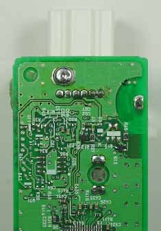
BGBX1T502SKE11A01
Aug 31, 2005Smart Keyless System (ECU)
Equipment Class
CYY - Communications Receiver used w/Pt 15 Transmitter