BRG-T21Wireless Accessory for Hearing Aid
Phonic Ear, Inc.
Click to zoom
Application Details
- Equipment Class
- TNT - Licensed Non-Broadcast Transmitter Worn on Body
- Date of Grant
- Mar 13, 2007
- Application Purpose
- Original Equipment
- Date of Application
- Mar 13, 2007
- Equipment Note
- Wireless Accessory for Hearing Aid
- Frequency Range
- 216.01250000 - 216.98750000
- Company
- Phonic Ear, Inc.
- Country
- United States
Documents & Files
Document Text
Text extracted from the exhibit documents filed with the FCC. Open a document above to read the original.
Users Manual
INSTRUCTIONS FOR USE Amigo T20/T21 2 Important notice Please familiarize yourself with the entire contents of this booklet before using your Amigo T20/T21. The booklet contains various statements, safety instructions and important information about the use and handling of the Amigo T20/T21 3 Contents Introduction 5 Typical package content 6 Overview of the T20/T21 7 Preparing your Amigo system 8 Inserting the battery 8 Charging the battery 9 Selecting language and country 11 The Amigo receivers 12 Changing the pin orientation 13 Attaching universal Amigo to a hearing instrument 14 Using Amigo with the Sumo R7 receiver 15 Choosing and changing channels 16 Synchronizing Amigo receivers 17 Synchronizing other manufacturers’ receivers 19 About channels 20 Using the TT-function (T21 only) 21 4 Connecting external audio sources (TV, MP3, etc.) 23 T20 and T21 special functions 24 LED/Display legend 27 Microphone options 28 Cleaning the T20/T21 29 Appendix A: Troubleshooting 30 Appendix B: Manufacturer’s warranty 32 5 Introduction Congratulations on your decision to take the next step in improving speech under- standing in the classroom. With the Amigo T20 and T21, you will experience all the benefi ts that come with a product family that is designed to meet the needs that arise through everyday use. The Amigo product is extremely versatile, making life much easier for users in school settings. The transmitters and receivers can be used with virtually all Behind-the-Ear hearing instruments, as well as cochlear implants (CI). 6 Typical package contents T20/T21 Charger Earphones Instruction Guide Aux cables Rechargeable AA battery Omni microphone 7 SYNC acts as the “ENTER” button “C” acts as the “CLEAR/EXIT” button. LED status indicator ON/OFF/Mute 2.5 mm microphone jack High resolution LCD display Team teaching (T21 only) Clear entered values Synchronise receiver/enter 3.5 auxiliary audio input jack “MiniB” USB charger jack Overview of the T20/T21 8 Preparing your Amigo system Inserting battery Remove the battery lid on the back of the transmitter and insert the rechargeable battery - remember to position the battery according to the markings (+/ -) on the label. Then replace the battery lid. The T20/T21 can then be used to charge the battery. Standard disposable Alkaline batteries cannot be charged in the unit. Note: The positive and negative ends of the battery may appear similar, so do double- check that the battery is positioned correctly. 9 Charging the battery To charge the battery, plug in the charger as shown in the picture. The Amigo T20/T21 uses one AA rechargeable NiMH battery, which must be charged for 14 hours before being used for the fi rst time. The T20/T21 offers failsafe charging, which prevents alkaline batteries being charged. Charging Error Check Battery! The display on the T20/T21 will indicate when the unit is charging. Also, the LED will turn on and shine green. Note: With a typical user pattern it is recommended to replace rechargeable batteries once every year, because the battery capacity will decrease over time. Battery charging 10 If you do not have time to charge the battery that came with the T20/T21, you can replace the battery with any of the following: • Special “silver-banded” rechargeable batteries (Only available through your hearing care professional, these are the only batteries that can be recharged inside the transmitter.) • Standard, rechargeable NiMH batteries These cannot be recharged inside the transmitter, but must be charged in a separate charger. • Standard, non-rechargeable alkaline batteries Can be used in an emergency, i.e. if you don’t have time to charge your rechargeable batteries. Alkaline batteries cannot be recharged. Note: Always dispose of old batteries in approved battery disposal bins. For more information please consult your Hearing Care Professional. 11 Select language and country (fi rst time only) Turn the transmitter on by pressing and holding the On/Off button for two seconds. Press ▲ or ▼ to select language, and confi rm by pressing the SYNC button. To select your country, use the ▲ or ▼ buttons, and confi rm by pressing the SYNC button. Select Language English Francais Deutsch • • • Select Country United States Canada Mexico • • • Note: Selecting a country will also select a predefi ned channel list, which contains all of the channels approved for use in that country. Warning: Only use channels approved for use in your country 12 LED status indicator 3-position mode switch Channel seek/toggle (R2 and R7 only) Note: Since Amigo receivers draw their power from the hearing aid battery, there is no reason to try to open the receiver casing. Never attempt to do this. The Amigo Receivers Europin connector Europin rotation lock 13 Changing the pin orientation If the pins on the Amigo receiver do not match the holes on the audio shoe, they can be rotated in steps of 90°. Simply pull the tab on BOTH sides of the receiver back simultaneously, move the pins and push the tab back in. Amigo receivers can be positioned with the LED facing to the front or the back. Note: To ensure optimal antenna performance, the Amigo receivers must be positioned with the LED facing either to the front or to the back. 14 Attaching universal Amigo receivers to a hearing instrument Amigo R1 and R2 receivers are attached to the hearing instrument via an audio shoe. First attach the receiver to the audio shoe. Then attach the audio shoe to the hearing instrument. 15 SUMO DM with the dedicated, Amigo R7 receiver. Using Amigo with the dedicated R7 receiver for Oticon Sumo hearing instruments • Sumo detects the receiver and disables the telecoil if the receiver is on • Operate the receiver from the hearing instrument 2 = FM only 1 = FM+Hearing instrument M = Hearing instrument only The use of the telecoil with the receiver attached requires that the receiver is set to the OFF position. Note: To obtain information about connecting your Amigo to Cochlear Implants, ple…
Text truncated - open the document above for the full version.
Users Manual
INSTRUCTIONS FOR USE Amigo WRP 2 Important notice Please familiarize yourself with the entire contents of this booklet before using your Amigo Wireless Receiver Programmer (WRP). The booklet contains various statements, safety instructions and important information about the use and handling of the Amigo WRP. 3 Content Introduction 5 Typical package contents 6 Overview of the WRP 7 Preparing your Amigo system 8 Inserting the battery 8 Charging the battery 9 Selecting language and country 11 The Amigo receivers 12 Changing the pin orientation 13 Attaching the universal Amigo receivers to a hearing instrument 14 Using Amigo with the Sumo R7 receiver 15 Synchronizing Amigo receivers 16 Accessing the Programming Menus 18 Overview of the menus of the R1/R2 19 Programming Amigo R1/R2 Receivers 20 Using the FM Channel Wizard (T20/21/WRP) 24 4 WRP Special functions 26 LED/Display legend 27 Cleaning the WRP 28 Appendix A: Troubleshooting 29 Appendix B: Manufacturers’ warranty 30 5 Introduction Congratulations on your decision to take the next step in improving classroom FM. The Amigo product family is extremely versatile, making life easier for users in school settings. The Amigo transmitters and receivers can be used with virtually all Behind- the-Ear hearing instruments, as well as many cochlear implants. 6 Typical package contents WRP Charger Monitoring Earphones Instructions for Use Rechargeable NiMH AA battery 7 Navigation buttons on the WRP SYNC acts as the “ENTER” button “C” acts as the “CLEAR/EXIT” button. ◄ acts as the “Save and Exit” button. LED status indicator ON/OFF/Mute 2.5 mm microphone jack High resolution LCD display Clear entered values (“C”) Synchronize receiver/enter 3.5 auxiliary audio input jack “MiniB” USB charge jack Overview of the WRP 8 Preparing your Amigo system Inserting battery Remove the battery lid on the back of the WRP and insert the rechargeable battery - remember to position the battery according to the markings (+/ -) on the label. Then replace the battery lid. The WRP can then be used to charge the battery that came in the package. Note: The positive and negative ends of the battery may appear similar, so doublecheck that the battery is positioned correctly. 9 Charging the battery To charge the battery, plug in the charger as shown in the picture. The Amigo WRP uses one AA rechargeable NiMH battery, which must be charged for at least 14 hours before being used for the fi rst time. The WRP offers failsafe charging, which prevents alkaline batteries being charged accidentally. Charging Error Check Battery! The display on the WRP will indicate when the unit is charging. Also, the LED will turn on and shine green. Note: With a typical user pattern it is recommended to replace rechargeable batteries once every year, because the battery capacity decreases each time it is charged. Battery charging 10 If you do not have time to charge the battery that came with the WRP, you can replace the battery with any of the following: • Special “silver-banded” rechargeable batteries (Only available through your Hearing Care Professional, these are the only batteries that can be recharged inside the transmitter.) • Standard, rechargeable NiMH batteries These cannot be recharged inside the transmitter, but must be charged in a separate charger (these batteries and charger are available at electronics stores). • Standard, non-rechargeable alkaline batteries Can be used in an emergency, i.e. if you don’t have time to charge your rechargeable batteries. Alkaline batteries cannot be recharged. Note: Always dispose of old batteries in approved battery disposal bins. For more information please consult your Hearing Care Professional. 11 Select language and country (fi rst time only) Turn the WRP on by pressing and holding the On/Off button for two seconds. Press ▲ or ▼ to select language, and confi rm by pressing the SYNC button. To select your country, use the ▲ or ▼ buttons, and confi rm by pressing the SYNC button. Select Language English Francais Deutsch • • • Select Country United States Canada Germany • • • Note: Selecting a country will also select a predefi ned channel list, which contains all of the channels approved for use in that country. Warning: Only use channels legal in your country. 12 LED status indicator 3-position mode switch Channel seek/toggle (R2 and R7 only) Note: Since Amigo receivers draw their power from the hearing instrument battery, they do not contain a power cell. Never attempt to open the receiver casing. The Amigo Receivers Europin connector Europin rotation lock 13 Changing the pin orientation If the pins on the Amigo receiver do not match the holes on the audio shoe, they can be rotated in steps of 90°. Simply pull the tab on both sides of the receiver back simultaneously, twist the pins and push the tab back in. Amigo receivers can be positioned with the LED facing to the front or the back. Note: To ensure optimal antenna performance, the Amigo receivers must be positioned with the LED facing either to the front or to the back. 14 Attaching the universal Amigo receivers to a hearing instrument Amigo R1 and R2 receivers are attached to the hearing instrument via an audio shoe. First plug the receiver into the audio shoe. Then attach the audio shoe to the hearing instrument. 15 SUMO DM with the dedicated, Amigo R7 receiver. Using Amigo with Sumo instruments • Sumo detects the Amigo receiver and disables the telecoil if the receiver is on • Set the switch on the R1/R2 receiver to FM+HA. You then must set the hearing aid switch as noted here to operate the receiver function. Use the receiver switch to turn the receiver off. 2/T = FM only 1/MT = FM+Hearing instrument M = Hearing instrument only The use of the telecoil with the receiver attached requires that the receiver is set to the off position. Note: To obtain information about connecting your Amigo to Cochlear Implants, please consult your Hearing Care Professional. 16 Synchronizing Amigo receivers …
Text truncated - open the document above for the full version.
External Photos
CETECOM ICT Services GmbH Untertürkheimer Str. 6-10, 66117 Saarbruecken Phone: +49 (0) 681 598-0 Fax: -9075 RSC-Laboratory Phone: +49 (0) 681 598-0 Fax: -9075 Test report no.: 2-4293-02-03/06 Date: 2006-07-04 Page 33 of 43 6 Photographs of Test Equipment Photo 1: CETECOM ICT Services GmbH Untertürkheimer Str. 6-10, 66117 Saarbruecken Phone: +49 (0) 681 598-0 Fax: -9075 RSC-Laboratory Phone: +49 (0) 681 598-0 Fax: -9075 Test report no.: 2-4293-02-03/06 Date: 2006-07-04 Page 34 of 43 Photo 2: CETECOM ICT Services GmbH Untertürkheimer Str. 6-10, 66117 Saarbruecken Phone: +49 (0) 681 598-0 Fax: -9075 RSC-Laboratory Phone: +49 (0) 681 598-0 Fax: -9075 Test report no.: 2-4293-02-03/06 Date: 2006-07-04 Page 35 of 43 Photo 3: CETECOM ICT Services GmbH Untertürkheimer Str. 6-10, 66117 Saarbruecken Phone: +49 (0) 681 598-0 Fax: -9075 RSC-Laboratory Phone: +49 (0) 681 598-0 Fax: -9075 Test report no.: 2-4293-02-03/06 Date: 2006-07-04 Page 36 of 43 Photo 4: CETECOM ICT Services GmbH Untertürkheimer Str. 6-10, 66117 Saarbruecken Phone: +49 (0) 681 598-0 Fax: -9075 RSC-Laboratory Phone: +49 (0) 681 598-0 Fax: -9075 Test report no.: 2-4293-02-03/06 Date: 2006-07-04 Page 37 of 43 Photo 5:
Internal Photos
CETECOM ICT Services GmbH Untertürkheimer Str. 6-10, 66117 Saarbruecken Phone: +49 (0) 681 598-0 Fax: -9075 RSC-Laboratory Phone: +49 (0) 681 598-0 Fax: -9075 Test report no.: 2-4293-02-03/06 Date: 2006-07-04 Page 38 of 43 Photo 6: Photo 7: CETECOM ICT Services GmbH Untertürkheimer Str. 6-10, 66117 Saarbruecken Phone: +49 (0) 681 598-0 Fax: -9075 RSC-Laboratory Phone: +49 (0) 681 598-0 Fax: -9075 Test report no.: 2-4293-02-03/06 Date: 2006-07-04 Page 39 of 43 Photo 8: Photo 9: CETECOM ICT Services GmbH Untertürkheimer Str. 6-10, 66117 Saarbruecken Phone: +49 (0) 681 598-0 Fax: -9075 RSC-Laboratory Phone: +49 (0) 681 598-0 Fax: -9075 Test report no.: 2-4293-02-03/06 Date: 2006-07-04 Page 40 of 43 Photo 10: Photo 11: CETECOM ICT Services GmbH Untertürkheimer Str. 6-10, 66117 Saarbruecken Phone: +49 (0) 681 598-0 Fax: -9075 RSC-Laboratory Phone: +49 (0) 681 598-0 Fax: -9075 Test report no.: 2-4293-02-03/06 Date: 2006-07-04 Page 41 of 43 Photo 12: Photo 13: CETECOM ICT Services GmbH Untertürkheimer Str. 6-10, 66117 Saarbruecken Phone: +49 (0) 681 598-0 Fax: -9075 RSC-Laboratory Phone: +49 (0) 681 598-0 Fax: -9075 Test report no.: 2-4293-02-03/06 Date: 2006-07-04 Page 42 of 43 Photo 14: Photo 15: CETECOM ICT Services GmbH Untertürkheimer Str. 6-10, 66117 Saarbruecken Phone: +49 (0) 681 598-0 Fax: -9075 RSC-Laboratory Phone: +49 (0) 681 598-0 Fax: -9075 Test report no.: 2-4293-02-03/06 Date: 2006-07-04 Page 43 of 43 Photo 16:
Test Report
CETECOM ICT Services GmbH Untertürkheimer Str. 6-10, 66117 Saarbruecken Phone: +49 (0) 681 598-0 Fax: -9075 RSC-Laboratory Phone: +49 (0) 681 598-0 Fax: -9075 Test report no.: 2-4293-02-03/06 Date: 2006-07-04 Page 1 of 43 Recognized by the Federal Communications Commission Anechoic chamber registration no.: 90462 (FCC) Anechoic chamber registration no.: 3463 (IC) TCB ID: DE 0001 Accredited by the German Accreditation Council DAR–Registration Number DAT-P-176/94-D1 Independent ETSI compliance test house ETSI Accredited Bluetooth ® Test Facility (BQTF) Test report no. : 2-4293-02-03/06 Applicant : Oticon A/S Type : Amigo Family (T20/T21/WRP) Test Standard : FCC Part 95 G RSS-210 Annex 4.3 FCC ID : BRG-T21 Certification No. IC : 1351B-T21 The Bluetooth word mark and logos are owned by the Bluetooth SIG, Inc. and any use of such marks by Cetecom ICT is under license CETECOM ICT Services GmbH Untertürkheimer Str. 6-10, 66117 Saarbruecken Phone: +49 (0) 681 598-0 Fax: -9075 RSC-Laboratory Phone: +49 (0) 681 598-0 Fax: -9075 Test report no.: 2-4293-02-03/06 Date: 2006-07-04 Page 2 of 43 Table of contents 1 GENERAL INFORMATION ............................................................................................................................. 3 1.1. ADMINISTRATIVE DATA OF THE TEST FACILITY................................................................................................ 3 1.1.1 Identification of the testing laboratory.................................................................................................... 3 1.2. NOTES.............................................................................................................................................................. 3 1.3 DETAILS OF APPLICANT................................................................................................................................... 4 1.4 APPLICATION DETAILS..................................................................................................................................... 4 1.5 TEST ITEM........................................................................................................................................................ 5 1.6 TEST STANDARDS............................................................................................................................................ 6 2 STATEMENT OF COMPLIANCE .................................................................................................................... 6 2.1 SUMMARY OF MEASUREMENT RESULTS.......................................................................................................... 6 2.2 TEST PROCEDURE............................................................................................................................................ 6 3 MEASUREMENTS AND RESULTS.................................................................................................................. 7 3.1 OUTPUT POWER (RADIATED) FCC RULE PART 95.639 (E) ............................................................................... 7 3.2 AFC FREQUENCY ERROR VS. VOLTAGE FCC RULE PART 95.629 ............................................................... 10 3.3 AFC FEQUENCY ERROR VS. TEMPERATURE................................................................................................... 10 3.4 CHARACTERISTICS OF THE AUDIO MODULATION CIRCUIRTY FCC RULE PART 2.1047 ................................. 11 3.5 OCCUPIED BANDWIDTH FCC RULE PART 95.633(D)(2), SEC. 2.1049 ........................................................... 12 3.6 EMISSION MASK FCC 95.635(C)(1) ............................................................................................................... 14 3.7 RADIATED EMISSIONS FCC RULE PART 95.635(C)(1) ................................................................................. 15 3.8 FCC PART 15 SUBPART B ..............................................................................................................................19 3.9 RECEIVER SPURIOUS RADIATION RADIATED § 15.109 ................................................................................ 20 3.11 CONDUCTED EMISSIONS § 15.107/207 ......................................................................................................... 23 4 USED TESTEQUIPMENT ................................................................................................................................ 24 5 PHOTOGRAPHS OF TEST SETUP ................................................................................................................ 28 6 PHOTOGRAPHS OF TEST EQUIPMENT .................................................................................................... 33 CETECOM ICT Services GmbH Untertürkheimer Str. 6-10, 66117 Saarbruecken Phone: +49 (0) 681 598-0 Fax: -9075 RSC-Laboratory Phone: +49 (0) 681 598-0 Fax: -9075 Test report no.: 2-4293-02-03/06 Date: 2006-07-04 Page 3 of 43 1 General information 1.1. Administrative data of the test facility 1.1.1 Identification of the testing laboratory Company name: Cetecom ICT Services GmbH Address: Untertürkheimerstr. 6-10 D-66117 Saarbruecken Germany Laboratory accreditation: DAR-Registration No. DAT-P-176/94-D1 Bluetooth Qualification Test Facility (BQTF) Federal Communications Commission (FCC) Identification/Registration No : 90462 Responsible for testing laboratory: Dirk Hausknecht Phone: +49 681 598 0 Fax: +49 681 598 9075 email: [email protected] 1.2. Notes The test results of this test report relate exclusively to the test item specified in 1.5. The CETECOM ICT Services GmbH does not assume responsibility for any conclusions and generalizations drawn from the test results with regard to other specimens or samples of the type of the equipment represented by the test item. The test report may only be reproduced or published in full. Reproduction or publication of extracts from the report requires the prior written approval of the …
Text truncated - open the document above for the full version.
Contact Information
Applicant
Mr. Michael Gibbs(Regulatory Affairs & QMS Manager)
Technical Specifications
| # | Rule Parts | Frequency Range | Power Output | Emission | Tolerance |
|---|---|---|---|---|---|
| 1 | 95G | 216.0125 MHz - 216.9875 MHz | 900.00 µW | 25K0F3E | 5.4295000000 ppm |
Other Applications from Phonic Ear, Inc.

BRG340T-216
Nov 10, 2005Portable Body Worn FM Transmitter
Equipment Class
TNT - Licensed Non-Broadcast Transmitter Worn on Body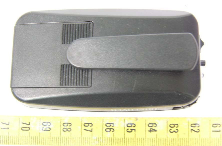
BRGPEPZT003
Oct 12, 2005Observer
Equipment Class
DSC - Part 15 Security/Remote Control Transmitter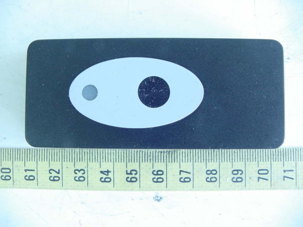
BRGPZO1
Apr 18, 2005Wireless Doorbell
Equipment Class
DSC - Part 15 Security/Remote Control Transmitter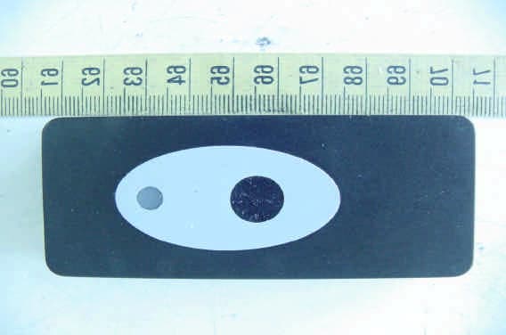
BRGDETECTDOOR
Mar 14, 2005Wireless Doorbell
Equipment Class
DSC - Part 15 Security/Remote Control Transmitter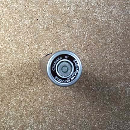
BRG922T
Apr 05, 2004Radium 216 Handheld Transmitter
Equipment Class
TNB - Licensed Non-Broadcast Station Transmitter