BRG340T-216Portable Body Worn FM Transmitter
Phonic Ear, Inc.
Click to zoom
Application Details
- Equipment Class
- TNT - Licensed Non-Broadcast Transmitter Worn on Body
- Date of Grant
- Nov 10, 2005
- Application Purpose
- Original Equipment
- Date of Application
- Nov 10, 2005
- Equipment Note
- Portable Body Worn FM Transmitter
- Frequency Range
- 216.02500000 - 216.97500000
- Company
- Phonic Ear, Inc.
- Country
- United States
Documents & Files
Document Text
Text extracted from the exhibit documents filed with the FCC. Open a document above to read the original.
Users Manual
user guide 340T Transmitter contents connecting CD, TV and other audio sources . . . . . . . . . . . . . . . . . . . . .16 340T part number cross-reference list .17-18 troubleshooting . . . . . . . . . . . . . . . . .19-20 caring for your 340T . . . . . . . . . . . . . . . .21 battery warnings . . . . . . . . . . . . . . . . . . .22 receivers that are compatible with the 340T transmitter . . . . . . . . . . . . . . . .23 340T channel numbers and corresponding frequencies . . . . . .24-26 product specifications . . . . . . . . . . . . . . .27 warranty . . . . . . . . . . . . . . . . . . . . . .28-30 regulatory approvals . . . . . . . . . . . . . .31-33 340T transmitter features . . . . . . . . . . .1- 2 340T available accessories . . . . . . . . . .3-4 340T microphone styles . . . . . . . . . . . . .5 340T setup and operation inserting batteries . . . . . . . . . . . . . . . . . . . .6 charging batteries using 230R sound field system . . . . . . . . . . . . . . . .7-8 charging batteries using wall charger . . . . . .9 wearing 340T . . . . . . . . . . . . . . . . . . . . .10 plugging in and wearing microphone . . . .11 activating microphone mute feature . . . . .12 turning on 340T . . . . . . . . . . . . . . . . . . .13 verifying channel setting . . . . . . . . . . . . . .14 changing channels . . . . . . . . . . . . . . . . . .15 1 340T transmitter features front back 1 2 3 5 4 top 68910 7 2 11 on/off(chg) switch 7LED power, mute, low battery and charging indicator light 2 channel up/down buttons 5 battery compartment 3 belt clip 6mute button ( on off) 8charging input jack (1.3mm) 10microphone input jack (2.5mm) 9auxiliary input jack (3.5mm) side 11 4 serial number/part number/operating band power on= Green light mute on= Blinking green light indicates that the microphone mute feature is on low batt= Blinking red light indicates approximately 1 hour of battery life remaining batt charging= Red light improper charging= no light (when charge cable is inserted) 1 LCD channel display 3 340T available accessories 1234 56 78 4 1340T carrying case (841-6440-101 - U.S./Canada) (895-88-008-00 - International) 2rechargeable NiMH AAA batteries (374-30-310-09) 4wall charger (040-7150-105 - US/Canada) (890-88-051-00 - International, UK, EU, NZ, AUS) 3elastic belt (AT0712) 5lavalier cord (AT0512-BK) 6aux-in adaptor cord (384-01-210-08) 3.5mm - 3.5mm connects 340T to external audio, CD player, stereo, computer, etc. 7aux-in adaptor cord (300-6332-107 - U.S./Canada) (384-88-005-00 - International) 3.5mm - dual RCA connects 340T to external audio, TV, VCR, DVD 8antenna (AT0529A) For use during auxiliary input only. 5 AT0814 earhook AT0655 behind-the-neck boom AT0291-L* lapel with lavalier cord AT0816 collar 340T microphone styles AT0164-L** omni lapel with lavalier cord * Lapel microphones are more prone to feedback when used with a sound field system. AT0667-L** omni lapel with lavalier cord ** Recommended for use with personal FM systems only AT0668-L* lapel mic with lavalier 6 1 inserting batteries Open battery compartment door by pressing and sliding downwards. 1 Insert rechargeable AAA NiMH batteries (or alkaline batteries) and replace door. Check polarity markings to confirm batteries are positioned correctly. 2 2 1 NOTE:The 340T uses high performance NiMH (nickel-metal hydride) batteries. To achieve maximum battery efficiency, charge batteries for 12 hours before first use. After daily use, charge unit overnight for at least 12 hours for up to 12 hours of battery life. 340T setup and operation 7 2a charging batteries using 230R sound field system Do NOTattempt to charge alkaline batteries in the 340T. Only Phonic Ear rechargeable batteries can be recharged. Push powerbutton to turn 230R receiver off. 1 Turn 340T power switch to off (chg)position. 3 1 then 3 Sleep/standby power light on 230R receiver will remain lit during power off mode. 2 2 8 2b charging batteries using 230R sound field system Do NOTattempt to charge alkaline batteries in the 340T. Only Phonic Ear rechargeable batteries can be recharged. 230R (back) Plug any end of charge cord into charge outjack on back of 230R receiver. 3 Plug any end of 300-6497-105 charge cord (included with 230R system) into 340T charge/ jack. 4 4 300-6497-105 3 5 NOTE: Charge for 12 hours before first use. After daily use, charge unit overnight for at least 12 hours for up to 12 hours of battery life. Check indicator light on 340T for proper charge indication. bright red= Battery charging green light= Improper charge (turn power to off(chg)position) 5 9 2c charging batteries using wall charger Do NOTattempt to charge alkaline batteries in the 340T. Only Phonic Ear rechargeable batteries can be recharged. Plug either end of the wall transformer charge cord into 340T chargejack. 3 IMPORTANT: Charge for 12 hours before first use. After daily use, charge unit overnight for at least 12 hours for up to 12 hours of battery life. 3 Plug wall transformer into wall socket. 2 2 (040-7150-105 - U.S./Canada) (890-88-051-00 - International) Switch 340T power to off (chg)position. 1 1 Verify 340T indicator light for proper charge indication bright red= Battery charging no light= Improper charge 4 4 10 3 wearing 340T Clip to elastic belt (AT0712), pocket, pants or clothes. or Attach transmitter to necklace-style lavalier cord (AT0512-BK). AT0712 AT0512-BK or 11 plugging in and wearing microphone 4 The microphone cord also acts as the antenna. To ensure consis- tent transmission, keep cord as straight as possible. Plug microphone into micjack on 340T unit. 1 2 2 1 Position microphone approximately 3in/7.6cm from mouth. 3 3 To mute microphone, press down on 340T mute button 4 12 activating microphone mute feature 5 1 3 To mute microphone, press down on 340T mute button mute switch positions: ( on off) 2 The green “power on” LED indi- cator light will begin to blink when mute feature is activated 3 To deactivate mute, press down again on the mute button to restore button to “up…
Text truncated - open the document above for the full version.
Cover Letter(s)
910805 1 Compliance Certification Services Certification Division 561F Monterey Road Morgan Hill, CA 95037 To whom it may concern: We, the undersigned, hereby authorize ELECTRONICS TESTING CENTER, TAIWAN, to act on our behalf in all manners relating to application for equipment authorization, including signing of all documents relating to these matters. Any and all acts carried out by ELECTRONICS TESTING CENTER, TAIWAN on our behalf shall have the same effect as acts of our own. We, the undersigned, hereby certify that we are not subject to a denial of federal benefits, that includes FCC benefits, pursuant to Section 5301 of the Anti-Drug Abuse Act of 1988, 21 U.S.C. 853(a). In authorizing ELECTRONICS TESTING CENTER, TAIWAN as our agent, we still recognize that we are responsible to: a) comply with the relevant provisions of the certification program; b) make all necessary arrangements for the conduct of the evaluation, including provision for examining documentation and access to all areas, records (including internal audit reports) and personnel for the purposes of evaluation (e.g. testing, inspection, assessment, surveillance, reassessment) and resolution of complaints; c) make claims regarding certification only in respect of the scope for which certification has been granted; d) do not use our product certification in such a manner as to bring the Certification Division into disrepute and not make any statement regarding our product certification which the Certification Division may consider misleading or unauthorized; e) upon suspension or cancellation of certification, discontinue use of all advertising matter that contains any reference thereto and return any certification documents as required by the Certification Division; 910805 2
Cover Letter(s)
1 Mike Kuo From: ssliou [[email protected]] Sent: Friday, November 11, 2005 12:10 AM To: Mike Kuo Cc: iris Subject: Re: Phonic Ear Inc., FCC ID: BRG340T-216, Assessment NO.: AN05T5288, Notice#1 Attachments: Exhibit-L-Tune-up Procedure_rev.pdf; Exhibit-D-ID_Label_rev.PDF Exhibit-L-Tune-up Procedure_re... Exhibit-D-ID_Label_ rev.PDF (95... Dear Mike, #1 and #2: Please find the revised t une-up procedure. #3: The labelling requirement of Part 95G was added. Please find attached the revised ID label. #4: The microphone cord or external antenna(AT0529A) when pluged into mic jack is the antenna of this equipment. Best regards, S. S. Liou Engineer / EMC Dept. II Electronics Testing Center, Taiwan ----- Original Message ----- From: "Mike Kuo" <[email protected]> To: <[email protected]>; "iris" <[email protected]> Sent: Friday, November 11, 2005 11:17 AM Subject: FW: Phonic Ear Inc., FCC ID: BRG340T-216, Assessment NO.: AN05T5288, Notice#1 -----Original Message----- From: Compliance Certification Services [mailto:[email protected]] Sent: Thursday, November 10, 2005 7:08 PM To: Mike Kuo Subject: Phonic Ear Inc., FCC ID: BRG340T-216, Assessment NO.: AN05T5288, Notice#1 Question #1: In the tune-up procedures, it stated that this device complied with Part 74 of FCC rules which does not agree with the applicable technical standard. Please make necessary correction. Question #2: Since this LPRS transmitter is designed to use specific channel, please update the frequency range in the tune-up procedure based upon the channel mapping listed in section 95.629(c). Question #3: Please address section 95.1017 labeling requirements. Question #4: Please point out the antenna location in the internal photos. Best Regards Mike Kuo 2 The items indicated above must be submitted before processing can continue on the above referenced application. Failure to provide the requested information within 30 days of the original e-mail date may result in application dismissal and forfeiture of the filing fee. Also, please note that partial responses increase processing time and should not be submitted. Any questions about the content of this correspondence should be directed to the e-mail address listed below the name of the sender.
External Photos
ETC Report No.:ET94R-08-141-01 Sheet 1 of 8 Sheets FCC ID.: BRG340T-216 Rev. 2.0 CONSTRUCTED PHOTOS of EUT A. 340T 1. Front View of EUT 2. Rear View of EUT ETC Report No.:ET94R-08-141-01 Sheet 2 of 8 Sheets FCC ID.: BRG340T-216 Rev. 2.0 CONSTRUCTED PHOTOS of EUT 3. Side View of EUT 4. SideView of EUT ETC Report No.:ET94R-08-141-01 Sheet 3 of 8 Sheets FCC ID.: BRG340T-216 Rev. 2.0 CONSTRUCTED PHOTOS of EUT 5. Top View of EUT 6. Buttom View of EUT ETC Report No.:ET94R-08-141-01 Sheet 6 of 8 Sheets FCC ID.: BRG340T-216 Rev. 2.0 CONSTRUCTED PHOTOS of EUT B. Adaptor 1. Top View of Adaptor 2. Bottom View of Adaptor
ID Label/Location Info
340T-216 Label Location Bottom View Label Here This device may not interfere with TV reception or Federal Government radar.
Internal Photos
ETC Report No.:ET94R-08-141-01 Sheet 4 of 8 Sheets FCC ID.: BRG340T-216 Rev. 2.0 CONSTRUCTED PHOTOS of EUT 7. Internal View of EUT ETC Report No.:ET94R-08-141-01 Sheet 5 of 8 Sheets FCC ID.: BRG340T-216 Rev. 2.0 CONSTRUCTED PHOTOS of EUT 8. Component View of PCB 9. Solder View of PCB ETC Report No.:ET94R-08-141-01 Sheet 7 of 8 Sheets FCC ID.: BRG340T-216 Rev. 2.0 CONSTRUCTED PHOTOS of EUT 3. Internal View of Adaptor ETC Report No.:ET94R-08-141-01 Sheet 8 of 8 Sheets FCC ID.: BRG340T-216 Rev. 2.0 CONSTRUCTED PHOTOS of EUT 4. Component View of Adaptor’s PCB 6. Solder View of Adaptor’s PCB
Parts List/Tune Up Info
340T Required information according to FCC 2.1033(c)(1)-(9) (1) Applicant and manufacture: Wireless microphone Phonic Ear Inc. 3880 Cypress Dr. Petaluma CA 94954 (ph) 707-769-1110 x284 (fx) 707-769-9624 (2) FCC ID: BRG340T-216 (3) Installation and Operation Instructions: Please fine user’s manual attached. (4) Type of Emission: 30KF3E (2D: 2X15=30kHz) (5) Frequency Range: 216.025-216.975 MHz (6) Power limit of applicable part: According to Part 95 subpart G, the maximum permissive power is 100mW. (7) The DC voltage applied to and DC current in to the several elements of the final RF amplifying device: DC 2.4V, below 100mA (8) Tune-up Procedure: 340T Tune-up Procedure 1. After AF final amplify via U6 of PCB. 2. The U7 is audio compressor. 3. Then adjust R35 to control AF level. 4. The audio frequency is modulated which can get RF signal via modulator VCO (U11). 5. The U17 is controller to correct the frequency. 6. The Osc. Signal coupled to power amplifier Q7 to get better RF level.
Test Report
Rev. 2.0 FCC Part 95 Subpart G EMI TEST REPORT of E.U.T. : Wireless Microphone (Transmitter) MODEL : 340T FCC ID. : BRG340T-216 Working Frequency : 216.025- 216.975MHz for APPLICANT : Phonic Ear, Inc. ADDRESS : 3880 Cypress Drive Petaluma, CA 94954-7600 Test Performed by ELECTRONICS TESTING CENTER, TAIWAN NO. 34, LIN 5, DING FU TSUN, LINKOU HSIANG TAIPEI HSIEN, TAIWAN, R.O.C. Tel:(02) 26023052 Fax:(02)26010910 http://www.etc.org.tw ; e-mail : [email protected] Report Number : ET94R-08-141-01 ETC Report No.:ET94R-08-141-01 FCC ID.: BRG340T-216 Rev. 2.0 TEST REPORT CERTIFICATION Applicant : Phonic Ear, Inc. 3880 Cypress Drive Petaluma, CA 94954-7600 Manufacturer : E-J Electronics Co., Ltd. 4F, NO.11, Lane 125, Sec 1, Kuo Kwang Rd., Ta Li City,Taichung Hsien,Taiwan Description of EUT a) Type of EUT : Wireless Microphone (Transmitter) b) Trade Name : PhonicEar c) Model No. : 340T d) Power Supply : DC 1.5V battery *2 e) Frequency Range : 216.025-216.975MHz Regulation Applied : FCC Rules and Regulations Part 95 Subpart G (2005) I HEREBY CERTIFY THAT; The data shown in this report were made in accordance with the procedures given in ANSI C63.4 and the energy emitted by the device was founded to be within the limits applicable. I assume full responsibility for accuracy and completeness of these data. Note: 1. The result of the testing report relate only to the item tested. 2. The testing report shall not be reproduced expect in full, without the written approval of ETC. Issued Date : Nov. 10, 2005 Test Engineer : (Falcon Shi) Approve & Authorized Signer : Will Yauo, Manager EMC Dept. II of ELECTRONICS TESTING CENTER, TAIWAN ETC Report No.:ET94R-08-141-01 FCC ID.: BRG340T-216 Rev. 2.0 Table of Contents Page 1 GENERAL INFORMATION..................................................................................................1 1.1 Product Description.................................................................................................................1 1.2 Characteristics of Device:........................................................................................................1 1.3 Test Methodology....................................................................................................................1 1.4 Test Facility..............................................................................................................................1 2 REQUIREMENTS OF PROVISIONS...................................................................................2 2.1 Definition.................................................................................................................................2 2.2 Frequencies Available..............................................................................................................2 2.3 Requirements for Radio Equipment on Certification..............................................................2 2.4 Labeling Requirement..............................................................................................................3 3 OUTPUT POWER MEASUREMENT...................................................................................4 3.1 Provision Applicable................................................................................................................4 3.2 Measurement Procedure...........................................................................................................4 3.3 Test Data..................................................................................................................................6 3.4 Result Calculation....................................................................................................................6 3.5 Measurement Instrument..........................................................................................................6 4 MODULATION CHARACTERISTICS................................................................................7 4.1 Provisions Applicable..............................................................................................................7 4.2 Measurement Method..............................................................................................................7 4.3 Measurement Instrument..........................................................................................................8 4.4 Measurement Result.................................................................................................................8 5 EMISSION BANDWIDTH....................................................................................................10 5.1 Provisions Applicable............................................................................................................10 5.2 Measurement Method............................................................................................................10 5.3 Measurement Instrument........................................................................................................10 5.4 Bandwidth Measured.............................................................................................................11 6 UNWANTED RADIATION...................................................................................................12 6.1 Provisions Applicable............................................................................................................12 6.2 Measurement Procedure.........................................................................................................12 6.3 Measuring Instrument............................................................................................................13 6.4 Measuring Data......................................................................................................................14 6.5 Radiated Measurement Photos...............................................................................................16 7 FREQUENCY STABILITY MEASUREMENT.........…
Text truncated - open the document above for the full version.
Test Setup Photos
ETC Report No.:ET94R-08-141-01 Sheet 16 of 32 Sheets FCC ID.: BRG340T-216 Rev. 2.0 6.5 Radiated Measurement Photos Mode: Tx ETC Report No.:ET94R-08-141-01 Sheet 17 of 32 Sheets FCC ID.: BRG340T-216 Rev. 2.0 Mode: Charging ETC Report No.:ET94R-08-141-01 Sheet 24 of 32 Sheets FCC ID.: BRG340T-216 Rev. 2.0 8.6 Photos of Conduction Measuring Setup Mode : Charging
Contact Information
Applicant
Mr. Michael Gibbs(Regulatory Affairs & QMS Manager)
Test Firm
Electronics Testing Center, TaiwanWin-Po Tsai
Technical Specifications
| # | Rule Parts | Frequency Range | Power Output | Emission | Tolerance |
|---|---|---|---|---|---|
| 1 | 95G | 216.025 MHz - 216.975 MHz | 209.00 µW | 30K0F3E | 50.0000000000 ppm |
Other Applications from Phonic Ear, Inc.

BRG-T21
Mar 13, 2007Wireless Accessory for Hearing Aid
Equipment Class
TNT - Licensed Non-Broadcast Transmitter Worn on Body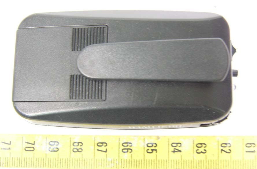
BRGPEPZT003
Oct 12, 2005Observer
Equipment Class
DSC - Part 15 Security/Remote Control Transmitter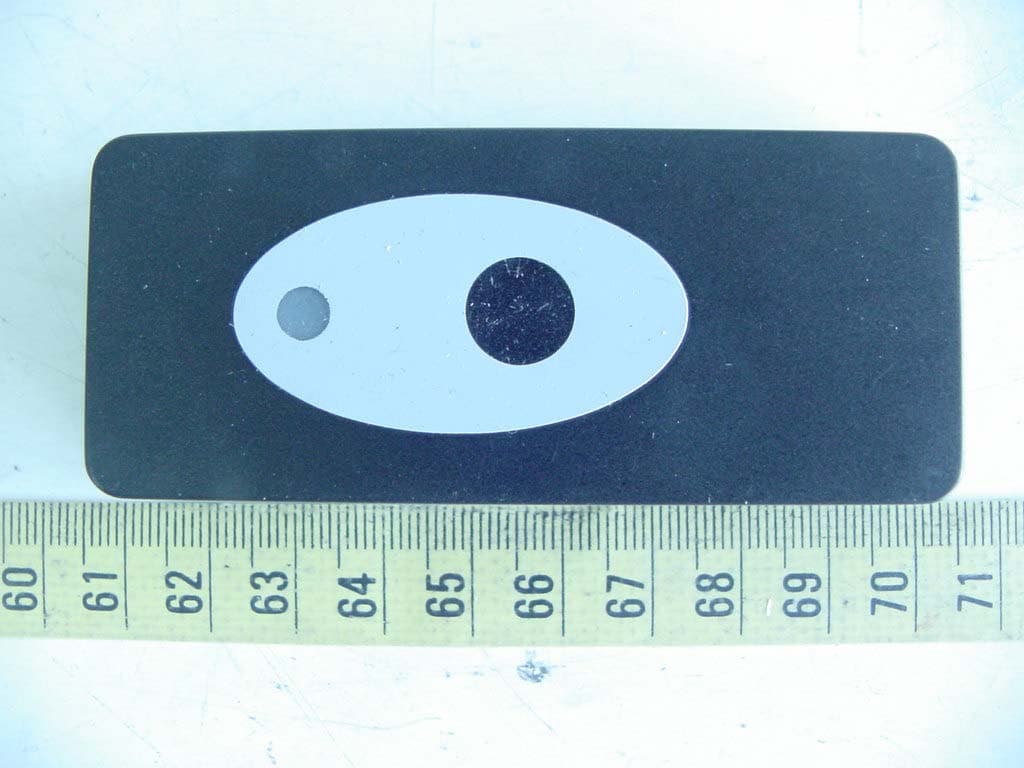
BRGPZO1
Apr 18, 2005Wireless Doorbell
Equipment Class
DSC - Part 15 Security/Remote Control Transmitter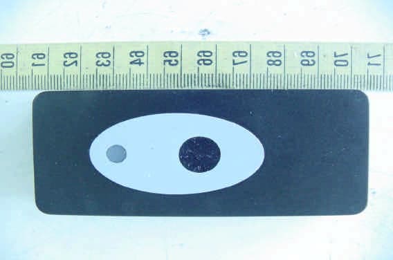
BRGDETECTDOOR
Mar 14, 2005Wireless Doorbell
Equipment Class
DSC - Part 15 Security/Remote Control Transmitter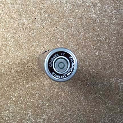
BRG922T
Apr 05, 2004Radium 216 Handheld Transmitter
Equipment Class
TNB - Licensed Non-Broadcast Station Transmitter