BRG922TRadium 216 Handheld Transmitter
Phonic Ear, Inc.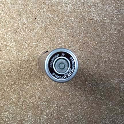
Click to zoom
Application Details
- Equipment Class
- TNB - Licensed Non-Broadcast Station Transmitter
- Date of Grant
- Apr 05, 2004
- Application Purpose
- Original Equipment
- Date of Application
- Apr 05, 2004
- Equipment Note
- Radium 216 Handheld Transmitter
- Frequency Range
- 216.02500000 - 216.87500000
- Company
- Phonic Ear, Inc.
- Country
- United States
Documents & Files
Document Text
Text extracted from the exhibit documents filed with the FCC. Open a document above to read the original.
Users Manual
user guide 920SR speaker 921T body-worn transmitter 922T handheld transmitter 923C charging stand 216MHz 3850 Radium216ug wnew FCC label 4/5/04 4:51 PM Page 2 contents 922T handheld transmitter operation . . . . . . . . . . . . . . . . . . . . . . . .34-39 connecting to auxiliary devices . . .40-42 additional accessories . . . . . . . . . . . .43-44 troubleshooting . . . . . . . . . . . . . . . . .45-46 Radium channel numbers and corresponding frequencies . . . . . . . . . . . .47 product specifications . . . . . . . . . . . . .48-50 warranty . . . . . . . . . . . . . . . . . . . . . .51-53 code of federal regulations . . . . . . . . .54-55 regulatory approvals . . . . . . . . . . . . . .56-57 introduction . . . . . . . . . . . . . . . . . . . . . . .1 understanding sound field . . . . . . . . . . . .2 installation tips . . . . . . . . . . . . . . . . . . . . .3 basic system guidelines . . . . . . . . . . . . . .4 accessories included with system . . . . . .5-6 920SR column speaker features . . . .7-10 921T body-worn transmitter features . .11-12 922T handheld transmitter features . . . .13 923C charging stand features . . . . . . . . .14 basic system setup and operation . . . . . . . . . . . . . . . . . . .15-23 920SR speaker placement and mounting . . . . . . . . . . . . . . . . . . .24-27 921T body-worn transmitter operation . . . . . . . . . . . . . . . . . . . . . . . .28-33 3850 Radium216ug wnew FCC label 4/5/04 4:51 PM Page 6 introduction Congratulations on the purchase of your new Radium sound field system! With proper care and use it will become one of your most valuable classroom educational tools. Students will be able to consistently and easily understand the teacher, regardless of their location in the classroom, or competing internal or external background noise. Teachers can speak all day in their normal voice, and will suffer far fewer vocal problems and absenteeism. Numerous studies show that classrooms using sound field enjoy better student comprehen- sion, increased student participation, better grades and fewer behavioral referrals. Read this manual carefully to become familiar with your system and to get the most out of it’s many features and options. 1 3850 Radium216ug wnew FCC label 4/5/04 4:51 PM Page 7 2 understanding sound field and its benefits ? • distance • noise • echo • vocal fatigue cough! • distance • noise • echo • vocal fatigue ? without sound field with sound field 3850 Radium216ug wnew FCC label 4/5/04 4:51 PM Page 8 3 Before you set your system up, take a good look around your room. Where are the outlets located? Where are the computers and other electronic equipment? Where can you put your speaker so it's easy for you to reach, but out of the way of students and main traffic areas? Though each classroom is different, there are some general guidelines for speaker placement: The speaker should be at the front of the classroom at least 6 feet/1.8 meters away from where the teacher stands. Try to keep it at least six feet away from computers or other electronic equipment, since there may be interference if placed too closely together. installation tips 3850 Radium216ug wnew FCC label 4/5/04 4:51 PM Page 9 basic system guidelines To help ensure that you get the most from this system, we have put together a list of sug- gested guidelines. Charge transmitter batteries every night.Our rechargeable Nickel Metal Hydride batteries last approximately 12 hours between charges, but should be recharged every night so they are ready to go in the morning. Plan on buying new NiMH batteries after 12 months of use. Alkaline batteries can also be used, and they will last approximately 15 hours. NEVER attempt to recharge alkaline batteries! This will cause damage to the transmitter units and may invalidate product warranty. Charge the 920SR receiver batteries every night.The column speaker rechargeable battery lasts approximately 5 - 8 hours between charges, but should be recharged every night so it’s ready to go in the morning. For daily use, we recommend unplugging the power supply cord, allowing the battery to power the unit. Continuous, daily operation with the power supply cord plugged in will reduce the life of the battery significantly. Do not coil the microphone cord.Since it also acts as your antenna, coiling or wrap- ping the cord will affect its range and may also reduce its life. Speak at a normal level— the system is projecting your voice for you. 4 3850 Radium216ug wnew FCC label 4/5/04 4:51 PM Page 10 5 accessories included with system 2 1 6 7 4 8 3 9 11 12 5 10 or or 3850 Radium216ug wnew FCC label 4/5/04 4:51 PM Page 11 6 10 channel changer screwdriver (330-3000-101) 6 receiver antenna (AT0831) 4power supply, receiver (040-7402-106) 9AA rechargeable NiMH batteries (AT0807) 5power supply, charging stand (040-7402-107) 8 elastic belt (AT0712) 1 column speaker receiver (920SR) 2 body-worn transmitter (921T) or handheld transmitter (922T) 3 charging stand (923C) 7 speaker table stand (AT0823) or wall mounting bracket (set of 2) (AT0820) 11 auxiliary input/output cable (AT0532-05) 12 auxiliary input cable (3.5mm – dual RCA) (300-6332-107) 3850 Radium216ug wnew FCC label 4/5/04 4:51 PM Page 12 7 920SR column speaker features (top) 2467 89 1 3 5 10 11 12 3850 Radium216ug wnew FCC label 4/5/04 4:51 PM Page 13 8 1 power, low battery, and reception status indicator for channel A 2 power switch and volume control for channel A 3 reception status indicator for channel B 12 aux output jack (3.5mm, mono) 4 power switch and volume control for channel B 8 antenna 11 aux input jack (3.5mm, mono) 7 aux output level switch See page 42 for level setting chart 5 tone control 6 aux input volume control 9 wall mount hole 10 extra antenna hole (not used) 3850 Radium216ug wnew FCC label 4/5/04 4:51 PM Page 14 9 920SR column speaker features (front and back) 13 14 15 16 17 20 18 19 3850 Radium216ug wnew FCC label 4/5/04 4:51 PM Page 15 10 14 two built-in speakers 16 handle 18 pow…
Text truncated - open the document above for the full version.
Cover Letter(s)
Response to E04-000026-1 1. The necessary bandwidth is 23K4 2. A revised confidentiality letter has been uploaded. 3. A revised label has been uploaded. 4. A revised test report has been uploaded. 5. A revised test report has been uploaded.
External Photos
Front Back Top Bottom Left Right
ID Label/Location Info
REFERENCE ONLY Page 1 of 2 TITLE Work Instruction for the FCC Label Placement, 922T DWG. NO. SK31904 922T REV. A Work Instruction for the FCC Label Placement, 922T SK31904 922T 3/25/04 A Init Release KC DATE REV REV RECORD AUTH 3880 Cypress Drive, Petaluma, CA 94954 CHECKED BY DATE David T APPROVED BY DATE Lee H REFERENCE ONLY Page 2 of 2 TITLE Work Instruction for the FCC Label Placement, 922T DWG. NO. SK31904 922T REV. A . FCC BAR CODE AND COUNTRY OF ORIGIN LABELS, AND LABEL PLACEMENT ` Country of Origin label (0.6 x 0.2”) “MADE IN TAIWAN” Place labels as shown. Label is to be legible. Labels to be provided by vendor. 0.968” 0.390” .062R TYP
Internal Photos
Interior Overall Top Interior Overall Bottom Front PCB Top & Small PCB Top Front PCB Top with Small PCB Small PCB Back Back PCB Top with Can Back PCB Top without Can Back PCB Back Antenna PCB Top Antenna PCB Bottom
Parts List/Tune Up Info
REFERENCE ONLY Page 1 of 4 TITLE Tune Up Procedure for the Radium 922T Xmtter DWG. NO. 810-7403-102 REV. A Tune Up Procedure for the Radium 922T Xmtter 810-7403-102 3/19/04 A Init Release DT DATE REV REV RECORD AUTH 3880 Cypress Drive, Petaluma, CA 94954 CHECKED BY DATE Dave T APPROVED BY DATE Lee H REFERENCE ONLY Page 2 of 4 TITLE Tune Up Procedure for the Radium 922T Xmtter DWG. NO. 810-7403-102 REV. A General description - The 922T is a lightweight handheld microphone containing a built in transmitter. The dimensions of the 922T are approximately 2.1” in diameter by 9.3” in length. The 922T handheld transmitter is designed to be in compliance with Part 95 Subpart G – Low Power Radio Service 95.1009 (a) and (b). The intended use of this product is to support language translation and /or auditory assistance in an educational setting. There are two connection points, two adjustment controls and a battery/low power indicator. Connection points: Microphone input – The 922T has a built-in dynamic microphone. A nominal input level of -35 dBV RMS will correspond to +/- 5 KHz peak deviation The 922T employs an automatic level control circuit to limit the peak deviation to less than +/- 8 kHz. This circuit is further described in the operation section of this report. Battery Charger contacts - Two contacts at the base of the microphone are provided to charge the internal rechargeable batteries if so equipped. The charger is composed of a desktop stand, allowing up to two units to be placed in the charger. Due to the physical nature of the 922T charger, the user is discouraged from operating the transmitter while it is in the charger stand. In addition, the charger output current is limited and unable to provide adequate current to support the operation of the unit while it is in the charging mode. Adjustment controls: On/Standby/Off- This is a three position slider switch located on the side of the unit. In the “Off” mode, all power to the unit is disconnected. In the “Standby” mode all the circuitry is active, but all audio signals are muted, resulting in an un-modulated RF carrier. The purpose of this mode is to allow the operator to have private comments but keep the transmitter and receiver units in a ready mode allowing fast re-acquisition when the “On” mode is selected. Channel Selection - This model features frequency synthesized channel selection. The channel spacing is set at 50 kHz and the design is capable of operation using extra band channels 41 though 60 (except channel 50) as defined in Part 95.629 section (c) (2). The current model supports only a 16 channel selection switch, located on the side of the unit, and Phonic Ear has chosen channels 41-48 and 51-58 as its 16 primary operating channel frequencies. At no point is channel 50 used. Indicator – A dual colored LED indicator is located on the side of the unit. When the indicator is green the unit is powered up and ready for operation. If the indicator turns red, a low battery condition exists and the user must recharge the unit or replace the internal batteries. The low battery indicator is set to trigger at approximately 2.1 Volts giving the operator adequate time to change batteries or replace it with a fully charged unit. All the frequency determining devices and modulation controls are powered by an internal, well regulated DC/DC converter. If the operator keeps using the unit past the low battery warning, the unit will continue to operate within FCC limits until the battery voltage reaches of approximately 1.2 Volts and the DC/DC converter simply shuts off. The 922T consists of two PCB’s, board “A” and board “B”, and a DC-DC converter module. The unit is designed for high volume production and requires a minimum amount of tuning up and alignment. REFERENCE ONLY Page 3 of 4 TITLE Tune Up Procedure for the Radium 922T Xmtter DWG. NO. 810-7403-102 REV. A Tune up procedure: 1. Place a 200 mA current limited operating voltage of 2.5 volts +/- .1 volts to battery terminals of the DUT. 2. Move the power switch to standby mode and verify the operating current is 90 mA +/- 30 mA. 3. Verify the DUT power indicator is green 4. Check to see the 6.5V supply is 6.5V +/- .2 at L2 (board A). 5. Check to see the 3.3V supply is 3.3V +/- .1 at the junction of L7 and C41 (board B). 6. Verify there is less than 20 mV pk-pk AC ripple on either the 6.5V or 3.3V supply. 7. Next check for proper operation of the 12 MHz reference clock by placing the RF probe near R27, XL1. Correct the reference to 12 MHz +/- 60 Hz ( 5 PPM ) by adjusting tuning capacitor VC1 8. Set the channel selector to channel “48” or 216.375 MHz. Using a voltmeter, measure the PLL tuning voltage at the positive side of C34 (board B). Verify the voltage is 2.0 +/- .2 Volts. If needed, change the value of C46 to bring the PLL tuning voltage with in tolerance. If the initial tuning voltage is too high, lower the value of C46. If the tuning voltage is too low, increase the value of C46. A suggested increment value is .5pF. 9. Change the channel selector to channel “41” and check to see if the PLL voltage is 1.8 +/- .2 Volts. 10. Change the channel selector to channel “58” and check to see if the PLL voltage is 2.2 +/- .2 Volts. 11. The PLL should be locked, and the PA enabled. Verify the operating current is now 100 mA +/- 10 mA. 12. Using an RF probe, verify the RF output power is 10 dBm +1/-3dB at the antenna port (board B) next to L25. 13. Place the RF output to an RF FM modulation analyzer. 14. Verify the DUT has less than 20 Hz of RMS residual FM deviation ( 300-15 KHz BW ) bandwidth. 15. With no audio input, switch the power switch to the “on” position. 16. Adjust the pilot tone VR2 (board A) to produce 825 Hz +/- 75 Hz of deviation. 17. Switch the audio bandwidth on the FM modulation analyzer to 300 – 3 kHz. 18. Place a -35 dBV RMS, 1 KHz audio tone to the microphone input. 19. Adjust modulation adjustment VR1 (board B) to produce +/- 5 KHz peak deviation. 20. Switch the a…
Text truncated - open the document above for the full version.
Test Report
Page 1 of 45 Report No.: FC04-024A ADDENDUM TO PHONIC EAR TEST REPORT FC04-024 FOR THE CLASSROOM AMPLIFICATION SYSTEM, PE922T FCC PART 95 AND RSS 210 COMPLIANCE DATE OF ISSUE: APRIL 2, 2004 PREPARED FOR: Phonic Ear 3880 Cypress Drive Petaluma, CA 94954-7600 PREPARED BY: Mary Ellen Clayton CKC Laboratories, Inc. 5473A Clouds Rest Mariposa, CA 95338 P.O. No.:P112518 W.O. No.:81873 Date of test:February 19 – April 2, 2004 Report No.: FC04-024A This report contains a total of 45 pages and may be reproduced in full only. Partial reproduction may only be done with the written consent of CKC Laboratories, Inc. The results in this report apply only to the items tested, as identified herein. Page 2 of 45 Report No.: FC04-024A TABLE OF CONTENTS Administrative Information..............................................................................................3 Summary of Results.........................................................................................................4 Conditions for Compliance..............................................................................................4 Approvals.........................................................................................................................5 Equipment Under Test (EUT) Description......................................................................5 Equipment Under Test.....................................................................................................5 Peripheral Devices............................................................................................................5 Measurement Uncertainty................................................................................................5 Temperature and Humidity During Testing.....................................................................6 FCC 2.1033(c)(3) User’s Manual.....................................................................................6 FCC 2.1033(c)(4) Type of Emissions..............................................................................6 FCC 2.1033(c)(5) Frequency Range................................................................................6 FCC 2.1033(c)(6) Operating Power.................................................................................6 FCC 2.1033(c)(7) Maximum Power Rating.....................................................................6 FCC 2.1033(c)(8) DC Voltages.......................................................................................6 FCC 2.1033(c)(9) Tune-Up Procedure.............................................................................6 FCC 2.1033(c)(10) Schematics and Circuitry Description..............................................6 FCC 2.1033(c)(11) Label and Placement.........................................................................6 FCC 2.1033(c)(12) Submittal Photos...............................................................................6 FCC 2.1033(c)(13) Modulation Information...................................................................6 FCC 2.1033(c)(14)/2.1046/95.637 - RF Power Output - Ant..........................................7 FCC 95.1013 - RF Power Output - OATS.......................................................................10 FCC 2.1033(c)(14)/2.1047(a) - Audio Frequency Response...........................................12 FCC 2.1033(c)(14)/2.1047(b) - Modulation Limiting Response.....................................13 FCC 2.1033(c)(14)/2.1049(i)/95.633 - Occupied Bandwidth..........................................16 FCC 95.635 - Emissions Mask.........................................................................................19 FCC 2.1033(c)(14)/2.1051/95.635(c) - Spurious Emissions at Antenna Terminal.........22 FCC 2.1033(c)(14)/2.1053/95.635(c) - Field Strength of Spurious Radiation................27 FCC 2.1033(c)(14)/2.1055(d) - Frequency Stability........................................................32 RSS 210 L2 6.2.2 - Emissions Mask................................................................................34 RSS 210 L2 6.2.2 - Spurious Emissions - OATS............................................................37 Page 3 of 45 Report No.: FC04-024A ADMINISTRATIVE INFORMATION DATE OF TEST:February 19 – April 2, 2004 DATE OF RECEIPT:February 19, 2004 PURPOSE OF TEST:To demonstrate the compliance of the Classroom Amplification System, PE922T with the requirements for FCC Part 95 and RSS 210 devices. Addendum A is to add the Canadian matrix and Canadian spurious emissions OATS data and revise the FCC spurious emissions OATS data. TEST METHOD:FCC Part 95 TIA/EIA 603 FREQUENCY RANGE TESTED:10 - 2200MHz MANUFACTURER:E-J Electronic Co. LTD 4F., No. 11, Lane 125, Sec. 1, Kuo Kwang Road, Ta-li City, Tachung Hsien, Taiwan REPRESENTATIVE:Lee Henderson TEST LOCATION:CKC Laboratories, Inc. 480 Los Viboras Road, Hollister, CA 95023 1120 Fulton Place, Fremont, CA 94539 5473-A Clouds Rest, Mariposa, CA 95338 Page 4 of 45 Report No.: FC04-024A SUMMARY OF RESULTS As received, the Phonic Ear Classroom Amplification System, PE922T was found to be fully compliant with the following standards and specifications: FCC Standard FCC Section Canadian Standard Canadian Section Test Description 47CFR15.203 RSS 2105.5 Antenna Connector Requirements 47CFR95.629 RSS 2106.2.2(L2) Two Way Voice Prohibited 47CFR95.637 RSS 2106.2.2(L2) Peak Output Power Requirements (100mW) 47CFR95.1013RSS 2106.2.2(L2) Peak Output Power Requirements FCC: 100mW ERP Canada: 160mW ERP NANA RSS 2106.2.2(L2) Canada Channel 13 Advisory 47CFR95.633 RSS 2106.2.2(L2) Emission Bandwidth 47CFR95.635 RSS 2106.2.2(L2) Emission Mask NANA RSS 2106.2.2(L2)Instrumentation for Mask (Peak 300Hz RBW) 47CFR15.205 RSS 2106.3 Restricted Bands of Operation 47CFR15.215(c) RSS 2106.4 Frequency Stability Recommendation 47CFR15.35(c) RSS 2106.5 Pulsed Operation 47CFR15.207 RSS 2106.6AC Mains Conducted Emissions Requirement TIA/EIA 603 Method FCC Site …
Text truncated - open the document above for the full version.
Test Setup Photos
PHOTOGRAPH SHOWING DIRECT CONNECT TEST SETUP PHOTOGRAPH SHOWING RADIATED EMISSIONS Radiated Emissions - Front View Radiated Emissions - Back View PHOTOGRAPH SHOWING AUDIO MODULATION TEST SETUP PHOTOGRAPH SHOWING TEMPERATURE TESTING
Contact Information
Applicant
Mr. Michael Gibbs(Regulatory Affairs & QMS Manager)
Technical Contact
CKC Laboratories, Inc.Mary Ellen Clayton
[email protected]209-966-5240
5473A Clouds Rest · Mariposa, California · United States
Non-Technical Contact
CKC Laboratories, Inc.Mary Ellen Clayton
[email protected]209-966-5240
Test Firm
CKC Laboratories, Inc.Steve Behm
Technical Specifications
| # | Rule Parts | Frequency Range | Power Output | Emission | Tolerance |
|---|---|---|---|---|---|
| 1 | 95G | 216.025 MHz - 216.875 MHz | 2.57 mW | 23K4F3E | 50.0000000000 ppm |
Other Applications from Phonic Ear, Inc.

BRG-T21
Mar 13, 2007Wireless Accessory for Hearing Aid
Equipment Class
TNT - Licensed Non-Broadcast Transmitter Worn on Body
BRG340T-216
Nov 10, 2005Portable Body Worn FM Transmitter
Equipment Class
TNT - Licensed Non-Broadcast Transmitter Worn on Body
BRGPEPZT003
Oct 12, 2005Observer
Equipment Class
DSC - Part 15 Security/Remote Control Transmitter
BRGPZO1
Apr 18, 2005Wireless Doorbell
Equipment Class
DSC - Part 15 Security/Remote Control Transmitter
BRGDETECTDOOR
Mar 14, 2005Wireless Doorbell
Equipment Class
DSC - Part 15 Security/Remote Control Transmitter