BRG300T216AProgrammable hearing instrument with FM receiver
Phonic Ear, Inc.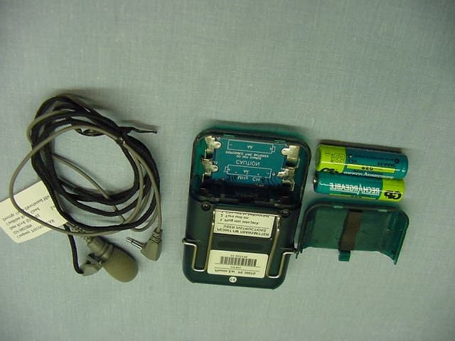
Click to zoom
Application Details
- Equipment Class
- TNT - Licensed Non-Broadcast Transmitter Worn on Body
- Date of Grant
- Dec 18, 2001
- Application Purpose
- Original Equipment
- Date of Application
- Dec 18, 2001
- Equipment Note
- Programmable hearing instrument with FM receiver
- Frequency Range
- 216.02500000 - 216.97500000
- Company
- Phonic Ear, Inc.
- Country
- United States
Documents & Files
Document Text
Text extracted from the exhibit documents filed with the FCC. Open a document above to read the original.
Users Manual
user guide PE 800R receiver PE 300TS transmitter PE 800R behind-the-ear FM system specs available on-line at www.phonicear.com 2625 Sprite User Guide Book 10/24/01 3:05 PM Page 2 Receiver: PE 800R. . . . . . . . . . . . . . . . . . . . . . . . . 1-2 Transmitter: PE 300TS . . . . . . . . . . . . . . . . . . . . . 3-4 sprite user instructions Wearing Transmitter/Microphone . . . . . . . . . . . . . . . 5 Hearing Instrument Battery . . . . . . . . . . . . . . . . . . . 6 Wearing Hearing Instrument/ Switch Functions . . . . . . . . . . . . . . . . . . . . . . . . . . . 7 Cartridge Removal/ Transmitter Batteries. . . . . . . . . . . . . . . . . . . . . . . . . 8 Using Sprite in Quiet Environment/ Using Sprite in Noisy Environment . . . . . . . . . . . . . . 9 Using Sprite in Group Conversations/ Using Sprite with TV or Stereo . . . . . . . . . . . . . . . . 10 Using Sprite with Telephone/ Using Sprite in Public Facilities . . . . . . . . . . . . . . . . 11 sprite fitter instructions Locking Battery Door . . . . . . . . . . . . . . . . . . . . . . . 12 Setting FM Gain Control . . . . . . . . . . . . . . . . . . . . 13 Installing/Removing Antenna . . . . . . . . . . . . . . . . . 14 Accessories . . . . . . . . . . . . . . . . . . . . . . . . . . . . 15-16 Caring for Your System . . . . . . . . . . . . . . . . . . . . . . 17 Code of Federal Regulations. . . . . . . . . . . . . . . . 18-19 Warranty . . . . . . . . . . . . . . . . . . . . . . . . . . . . . . . 20 Troubleshooting . . . . . . . . . . . . . . . . . . . . . . . . 21-22 Other Important Information . . . . . . . . . . . . . . . . . 23 table of contents 2625 Sprite User Guide Book 10/24/01 3:05 PM Page 4 receiver: PE 800R 1 side 1 2 3 8 9 4 5 11 12 7 13 14 6 back 2 3 34 5 6 7 + - T 26 F M F M T M T M front 10 10 10 2625 Sprite User Guide Book 10/24/01 3:05 PM Page 5 2 receiver: PE 800R (cont’d) 2 cartridge selector switch Activates left or right cartridge (see3and4) 3 FM channel cartridge Insert in left or right slot. Make sure channel matches that of transmitter(s). A second FM channel allows easy switching to hear a different speaker or avoid interference. 1antenna Removeable 5volume control User-adjustable ± 15dB (in 2dB increments) from prescribed gain level. “+” to increase; “-” to decrease. Can be locked with pro- gramming software. Unit always powers up at pre- scribed gain. 4telecoil cartridge Insert in right slot only (for telephone and loop use) 7on /off switch/ battery door Closed = on; Open = off 6mode switch (three-position) FM: F = FM only M = Mic + FM F M = Mic only t-coil: T= t-coil only M = Mic + t-coil T M = Mic only 8locking screw Locks battery door 9locking screw access hole Provides access to locking screw 10model indicia “P” indicates Power model, “M” indicates Moderate 11microphone 12earhook Various types are available 13plastic tubing Replace when yellow or stiff (not included with system) 14earmold (not included with system) 2625 Sprite User Guide Book 10/24/01 3:05 PM Page 8 transmitter: PE 300TS 3 front back 15 16 18 19 20 top 21 22 17 2625 Sprite User Guide Book 10/24/01 3:05 PM Page 9 4 transmitter: PE 300TS (cont’d) 15 on/off switch On/Off (72MHz and 173MHz) On/Mute/Off (216MHz) 16 charging indicator Glows red when charging NiCad batteries (never recharge alkaline batteries!) 17 transmitter band label Indicates operating band of transmitter 20 battery compartment Use AA rechargeable NiCad or disposable alkaline batteries (never recharge alkaline batteries!) 19 belt clip 21 microphone jack Plug in a microphone or an antenna (if using auxiliary input alone) 22 auxiliary/charge jack Connect to a CD player or other sound source with the AT0532 cord; connect to personal charger to recharge NiCad batteries (never recharge alkaline batteries!) To comply with FCC radio-frequency exposure requirements, this device must be worn with the belt clip provided with the device. Use of accessories/ configurations not approved by Phonic Ear may result in non-compliance with FCC RF exposure limit, and therefore should be avoided. 18 channel number Make sure the channel matches your receiver 2625 Sprite User Guide Book 10/24/01 3:05 PM Page 12 Sprite user instructions 5 power Clip to belt or wear around neck 15cm/6in max. Clip microphone to clothing or to lavalier cord then Plug in microphone Microphone cord also functions as the antenna. It is important to keep the cord as straight as possible. Do not coil. wearing transmitter/microphone user 1 2 3 2625 Sprite User Guide Book 10/24/01 3:05 PM Page 13 6 Sprite user instructions (cont’d) on/off Open battery door battery Insert battery in door. Make sure battery “+” is on same side as “+” on battery door on (battery door closed) The battery door is the on/off switch + indicator off (battery door open) hearing instrument battery Press on symbol to close door user user 1 2 2625 Sprite User Guide Book 10/24/01 3:05 PM Page 16 Sprite user instructions (cont’d) 7 FM only (when using FM) Mic + FM Mic only T-coil only (when using T-coil) Mic + T-coil Mic only + - T 26 F M F M T M T M + = Increase volume by one 2dB step - = Decrease volume by one 2dB step Switch left to activate left cartridge; right to activate right cartridge FM channel cartridge FM channel or t-coil cartridge (t-coil must be on right side) switch functions wearing your hearing instrument Turn off Insert top of earmold under fold Pull down lobe and press earmold into canal Place S PRITEbehind ear Turn on 1 2 3 4 5 user user 2625 Sprite User Guide Book 10/24/01 3:05 PM Page 17 8 Sprite user instructions (cont’d) FM channel cartridge (2 pins) Insert in left or right slot telecoil cartridge (3 pins) Insert in right slot only key Insert cartridges such that the keys and pins align cartridge removal Plug in second charging 300TS PE 300TS AUX/ CHG replacing batteries Push to slide off Charge every night for 12 hours NEVER CHARGE ALKALINE BATTERIES! Charge only rechargeable NiCad batteries AT0534 Plug in first Be sure to inse…
Text truncated - open the document above for the full version.
Users Manual
12 Sprite fitter instructions To lock or unlock battery door, open door to first detent (where the “+” sign is visible). The locking screw should be visible through the locking screw access hole. AT0066 screwdriver To unlock, turn counter-clockwise (about 2-3 turns) until door opens without catching ”+” sign locking screw locking hole To lock, turn the locking screw clockwise until it turns no further lock unlock locking screw locking battery door fitter 2625 Sprite User Guide Book 10/24/01 3:05 PM Page 26 Sprite fitter instructions (cont’d) 13 FM gain control adjusts FM relative to HA gain and has 20dB of adjustable range. It’s factory set to equal gain. Clockwise increases FM gain, counterclockwise decreases it. battery door bottom view FM gain control battery setting FM gain control FM HA FM HA Increases FM gain Decreases FM gain fitter 2625 Sprite User Guide Book 10/24/01 3:05 PM Page 23 14 Sprite fitter instructions (cont’d) installing/removing antenna to install Depress antenna button with fingernail and insert antenna antenna to remove Depress antenna button with fingernail and gently pull antenna out antenna fitter 2625 Sprite User Guide Book 10/24/01 3:05 PM Page 22 15 accessories transmitter accessories microphones Noise-canceling behind-the-neck microphone with mute (AT0655M) Directional lapel microphone with mic clip and lavalier cord (AT0668-L) • Extra windscreen (AT0668-W) • Extra clip (AT0668-C) Omni-directional lapel microphone with mic clip and lavalier cord (AT0667-L) • Extra windscreen (AT0667-W) • Extra clip (AT0667-C) Conference microphone (AT0720) • Daisy-chaining cord (AT0721) wearing options Lavalier cord (AT0512) Hip pack (AT0594) Wire belt clip (AT0489) Waist belt (AT0712) miscellaneous Wall transformer/two-unit charger (AT0534) 2 rechargeable NiCad batteries (AT0665) Mic jack antenna (AT0529A) AUX input patch cord – 1.5m, 4.5m/ 5ft, 15ft (AT0532) 2625 Sprite User Guide Book 10/24/01 3:05 PM Page 19 16 accessories (cont’d) receiver accessories earhooks Standard (AT0596 SU) Peak-damping (AT0596 SD) Child’s standard (AT0597 MU) Child’s peak-damping (AT0597 MD) High Pass (AT0718 – High) Low Pass (AT0718 – Low) Notch Filter (AT0718 – Notch) miscellaneous Presentation bag (AT0771) Presentation bag insert (AT0772) Battery pack (10 pack of four 675-size) (AT0631) T-coil cartridge (AT0754) 72MHz receiver oscillator (AT0751) 173MHz cartridge (AT0752) 216MHz cartridge (AT0753) Blank cartridge (AT0826) 72MHz antenna • Black (AT0750-72B) • Green (AT0750-72G) 173MHz Antenna • Black standard (AT0750-173B) • Green standard (AT0750-173G) • Black extended (AT0750-173BL) • Green extended (AT0750-173GL) 216MHz Antenna • Black standard (AT0750-216B) • Green standard (AT0750-216G) • Black extended (AT0750-216BL) • Green extended (AT0750-216GL) Handheld Programmer (PE 801) • Programmer cable left (AT0748L) • Programmer cable right (AT0748R) NOAH Programming Cables • NOAH cable left (AT0808L) • NOAH cable right (AT0808R) Screwdriver (AT0066) Stethoset (AT0605) 2625 Sprite User Guide Book 10/24/01 3:05 PM Page 18 17 caring for your system • Avoid contorting the antenna. • Always dispose of old batteries in approved battery recycling bins. It may be illegal to dispose of batteries in the trash. If you are not sure of proper disposal method, consult your local authority. clean your system nightly Transmitter Clean as needed, using a soft, damp cloth. Hearing instrument We recommended that you clean your hearing instrument with a soft, damp cloth Earmolds Earmolds must be kept clean at all times so sound can be channeled clearly to the ears. Disconnect the earmold and tubing from the hearing instrument, then clean earmolds with mild soap and water only. Never use alcohol or solvents. If the earmolds become clogged with wax, gently push a soft, absorbent cotton pipe cleaner through the opening to clear it. Make sure the earmold and tubing are completely dry before reconnecting to the hearing instrument–if necessary, use a special blower available from your hearing care professional. storage Temporary When not wearing your S PRITE, keep it safely protected in its case. Also store extra channel cartridges, screwdriver, and batteries in the spaces provided in the case. Adhere or insert an identification tag to the side or inside of the case. Long-Term Follow instructions as above, but remove the batteries before placing the receivers into their case. other important notes • Protect your hearing instrument from excess humidity (shower, bathing), heat (radiator, car in summer) and shocks. Remove hearing instruments before using hair spray. 2625 Sprite User Guide Book 10/24/01 3:05 PM Page 15 18 code of federal regulations (United States only) Part 21 and Part 801.420 – applies to U.S. products only The 800R S PRITEBTE-FM system is hearing instrument with a built-in FM receiver. It will not restore normal hearing, and will not prevent or improve a hearing impairment resulting from organic conditions. Infrequent use of a hearing instrument usually does not permit the user to attain the full benefits of the system. Remember that this instrument is only part of the hearing habilitation, and may need to be supplemented by auditory training and instruction in lip reading. Phonic Ear FM receivers and FM transmitters, when required, are approved by the Federal Communications Commission in the U.S. and Industry Canada. Other government approvals available upon request. (Other international regula- tions may also apply.) NOTE: FCC Rules, Part 15, Subpart A, 15.19 (a)(3) and (c.) This device com- plies with part 15 of the FCC rules. Operation is subject to the following two conditions: (1) this device may not cause harmful interference, and (2) this device must accept any interference received, including interference that may cause undesired operation. Any changes or modifications made to any government-approved element of this instrument, without the expressed approval of Phonic Ear Inc. in writing, coul…
Text truncated - open the document above for the full version.
External Photos
Transmitter External Photo FCC IC: BRG300T216A Transmitter External Photo FCC IC: BRG300T216A Transmitter External Photo FCC IC: BRG300T216A
ID Label/Location Info
FCC ID BRG300T216A
Internal Photos
Transmitter Internal Photo FCC IC: BRG300T216A Transmitter Internal Photo FCC IC: BRG300T216A Transmitter Internal Photo FCC IC: BRG300T216A Transmitter Internal Photo FCC IC: BRG300T216A Transmitter Internal Photo FCC IC: BRG300T216A
RF Exposure Info
Specific Absorption Rate (SAR) Test Report for Phonic Ear, Inc. on the Low Power Radio Service Station Model: BTE-FM 216 FCC ID: BRG300T216A Test Report: 20426253a Date of Report: April 30, 2001 Job #: J20042625 Date of Test: April 30, 2001 Total No of Pages Contained in this Report: 29. Tested by:Suresh Kondapalli, Test Engineer Reviewed by: Ollie Moyrong, EMC Manager All services undertaken are subject to the following general policy: Reports are submitted for exclusive use of the client to whom they are addressed. Their significance is subject to the adequacy and representative character of the samples and to the comprehensiveness of the tests, examinations or surveys made. This report shall not be reproduced except in full, without written consent of Intertek Testing Services, NA Inc.. 1365 Adams Court, Menlo Park, CA 94025 Phonic Ear, Inc., Model No: BTE-FM 216 Date of Test: April 30, 2001 FCC ID: BRG300T216A File: 20426253aPage 1 of 29RSS-102 & FCC Part 2 SAR Evaluation Table of Contents 1.0JOB DESCRIPTION................................................................................................................2 1.1Client Information..........................................................................................................2 1.2Equipment under test (EUT)...........................................................................................2 1.3Test plan reference.........................................................................................................3 1.4System test configuration................................................................................................4 1.4.1System block diagram & Support equipment......................................................4 1.4.2Test Position......................................................................................................5 1.4.4Test Condition...................................................................................................6 1.5Modifications required for compliance............................................................................6 1.6Additions, deviations and exclusions from standards.......................................................6 2.0SAR EVALUATION.................................................................................................................7 2.1SAR Limits.....................................................................................................................7 2.2Configuration Photographs.............................................................................................8 2.3System Verification......................................................................................................10 2.4Evaluation Procedures..................................................................................................10 2.5Test Results..................................................................................................................11 3.0TEST EQUIPMENT...............................................................................................................13 3.1Equipment List.............................................................................................................13 3.2Muscle Tissue Simulating Liquid..................................................................................14 3.3E-Field Probe Calibration.............................................................................................14 3.4Measurement Uncertainty.............................................................................................15 3.5Measurement Tractability.............................................................................................15 4.0WARNING LABEL INFORMATION - USA........................................................................16 5.0REFERENCES........................................................................................................................17 6.0DOCUMENT HISTORY........................................................................................................18 APPENDIX A - SAR Evaluation Data................................................................................................19 APPENDIX B - E-Field Probe Calibration Data................................................................................21 1365 Adams Court, Menlo Park, CA 94025 Phonic Ear, Inc., Model No: BTE-FM 216 Date of Test: April 30, 2001 FCC ID: BRG300T216A File: 20426253aPage 2 of 29RSS-102 & FCC Part 2 SAR Evaluation 1.0JOB DESCRIPTION 1.1 Client Information The BTE-FM 216 has been tested at the request of Company:Phonic Ear, Inc. 3880 Cypress Drive Petaluma, CA 94954 USA Name of contact:Ms. Barbara Brown Telephone:(707) 769-1110 Fax:(707) 769-9624 1.2 Equipment under test (EUT) Product Descriptions: EquipmentLPRS Trade NamePhonic EarModel No.BTE-FM 216 FCC IDBRG300T216AS/N No.Not Labeled CategoryN/ARF ExposureUncontrolled Frequency Band216.025-216.975 MHzSystemFM Radio EUT Antenna Description Type Wire Configuration Fixed, 360° Rotation Dimensions1 mGain 0 dBi Use of Product:The BTE-FM 216 behind-the-ear FM system is a hearing instrument with built-in FM receiver. Manufacturer:SAME as above. Production is planned:[X] Yes, [ ] No EUT receive date:March 28, 2001 EUT received condition:Good working condition prototype Test start date:April 30, 2001 Test end date:April 30, 2001 1365 Adams Court, Menlo Park, CA 94025 Phonic Ear, Inc., Model No: BTE-FM 216 Date of Test: April 30, 2001 FCC ID: BRG300T216A File: 20426253aPage 3 of 29RSS-102 & FCC Part 2 SAR Evaluation 1.3Test plan reference FCC rule part 2.1093, FCC Docket 96-326 & Supplement C to OET Bulletin 65 1365 Adams Court, Menlo Park, CA 94025 Phonic Ear, Inc., Model No: BTE-FM 216 Date of Test: April 30, 2001 FCC ID: BRG300T216A File: 20426253aPage 4 of 29RSS-102 & FCC Part 2 SAR Evaluation 1.4System test configuration 1.4.1System block diagram & Support equipment The EUT was teste…
Text truncated - open the document above for the full version.
Test Report
FCC Part 95(G) Test Report ,. FCC ID: BRGJOOT216A Job No: 120042625 Date of Test: March 28,2001 Report No.: 20426251a Date of Report: March 30, 200 1 Warnock HersE --- .i&- All services undertaken are subject to the tollowing general policy: Reports are submitted for exclusive use of the client to whom they are addressed. Their signifiCaJlce is subject to the adequacy mld representlttive character of the samples and to the comprehensiveness of the tests, examillations or surveys made. This report sha.lnot be reproduced except in full, without written consent ofhttertek Testing Services, NA fuc. , ,, ~ -m1- ~. enx: ~ Intertek Testing Services NA, Inc. 27611 La Paz Road, Suite C, Laguna Niguel, CA 92677 Telephone 949-448-4100 Fax 949-448-4111 Home Page www.etlsemko.com lOr Phonic Ear Inc. on the Low Power Radio Service Station Model: BTE-FM 216 1365 Adams Court, Menlo Park, CA 94025 Phonic Ear., Model No: BTE-FM 216Date of Test: March 28, 2001 FCC ID: BRG300T216A File: 20426251aVersion 1.0Page 1 FCC Part 95 TABLE OF CONTENTS 1.0Job Description.......................................................................................................................3 1.1Client Information.......................................................................................................3 1.2Equipment under test (EUT)........................................................................................3 1.3Test plan reference......................................................................................................4 1.4System test configuration.............................................................................................4 1.4.1System block diagram & Support equipment...................................................4 1.4.2Justification.....................................................................................................5 1.4.3Mode(s) of operation.......................................................................................5 1.4.4Modifications required for compliance............................................................5 2.0Test Summary........................................................................................................................6 3.0Effective Radiated Power.......................................................................................................7 3.1Test Description..........................................................................................................7 3.2Test Procedure.............................................................................................................7 3.3Test Results.................................................................................................................7 3.4Modifications made during testing...............................................................................8 3.5Test Instrumentation....................................................................................................8 4.0Modulation Characteristics....................................................................................................9 4.1Test Description..........................................................................................................9 4.2Test Procedure.............................................................................................................9 4.2.1Audio Frequency Response.............................................................................9 4.2.2Modulation Limiting.......................................................................................9 4.3Test Results.................................................................................................................9 4.4Modifications made during testing..............................................................................12 4.5Test Instrumentation...................................................................................................12 5.0Occupied Bandwidth.............................................................................................................13 5.1Test Description.........................................................................................................13 5.2Test Procedure............................................................................................................13 5.3Modifications made during testing..............................................................................13 5.4Test instrumentation...................................................................................................13 5.5Test Results (Plots).....................................................................................................14 6.0Field Strength of Spurious Radiation...................................................................................22 6.1Test description..........................................................................................................22 6.2Test Procedure............................................................................................................22 6.3Test Instrumentation...................................................................................................22 6.4Test Results................................................................................................................23 7.0AC Line Conducted Emissions.............................................................................................28 7.1Test Description.........................................................................................................28 7.2Test Procedure............................................................................................................28 1365 Adams Court, Menlo Park, CA 94025 Phonic Ear., Model No: BTE-FM 216Date of Test: March 28, 2001 FCC ID: BRG300T216A File: 20426251aVersion 1.0Page 2 FCC Part 95 7.3Modifications made during testing........................................…
Text truncated - open the document above for the full version.
Test Setup Photos
Test Setup Photo FCC IC: BRG300T216A
Contact Information
Applicant
Mr. Michael Gibbs(Regulatory Affairs & QMS Manager)
Technical Contact
Intertek Testing ServicesOllie Moyrong
[email protected]650-463-2900
1365 Adams Court · Menlo Park, California · United States
Non-Technical Contact
Intertek Testing ServicesStephanie Smith
[email protected]650-463-2900
Test Firm
Intertek Testing Services NA Inc.John Quigley
Technical Specifications
| # | Rule Parts | Frequency Range | Power Output | Emission | Tolerance |
|---|---|---|---|---|---|
| 1 | 95G | 216.025 MHz - 216.975 MHz | 6.00 mW | 26K8F3E | 19.0000000000 ppm |
Other Applications from Phonic Ear, Inc.

BRG-T21
Mar 13, 2007Wireless Accessory for Hearing Aid
Equipment Class
TNT - Licensed Non-Broadcast Transmitter Worn on Body
BRG340T-216
Nov 10, 2005Portable Body Worn FM Transmitter
Equipment Class
TNT - Licensed Non-Broadcast Transmitter Worn on Body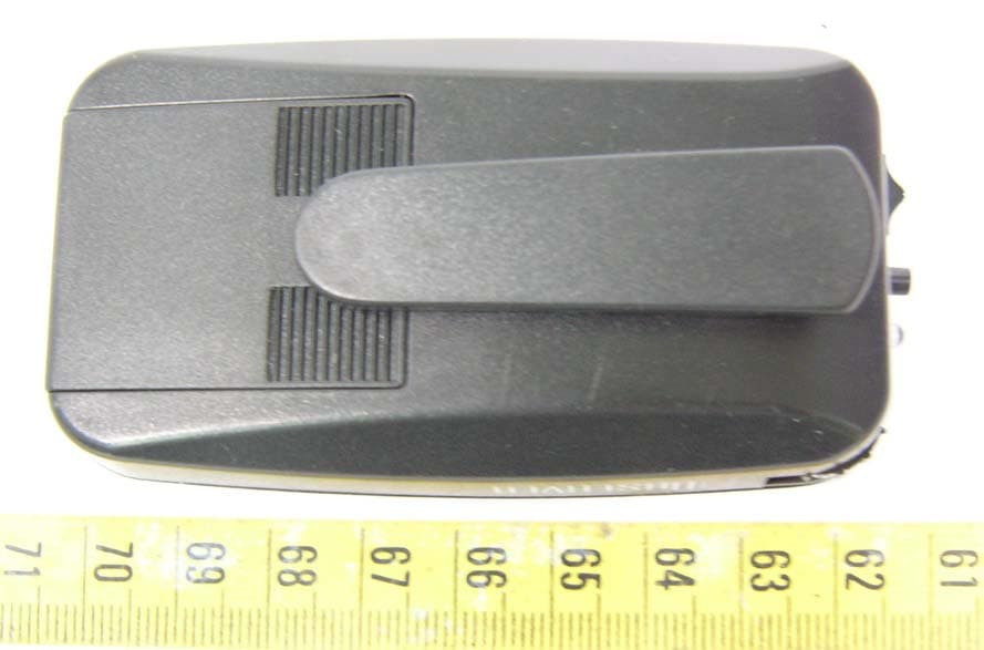
BRGPEPZT003
Oct 12, 2005Observer
Equipment Class
DSC - Part 15 Security/Remote Control Transmitter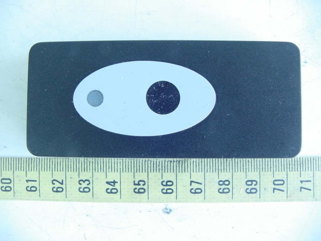
BRGPZO1
Apr 18, 2005Wireless Doorbell
Equipment Class
DSC - Part 15 Security/Remote Control Transmitter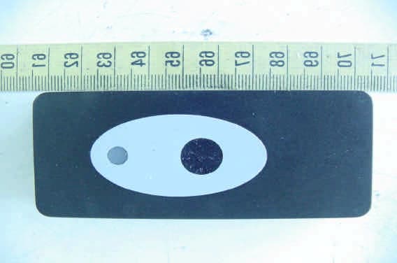
BRGDETECTDOOR
Mar 14, 2005Wireless Doorbell
Equipment Class
DSC - Part 15 Security/Remote Control Transmitter