BRG330T216Easy Listener II Transmitter
Phonic Ear, Inc.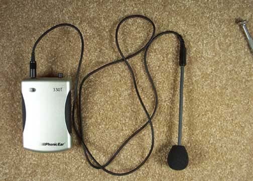
Click to zoom
Application Details
- Equipment Class
- TNT - Licensed Non-Broadcast Transmitter Worn on Body
- Date of Grant
- Mar 08, 2004
- Application Purpose
- Original Equipment
- Date of Application
- Mar 08, 2004
- Equipment Note
- Easy Listener II Transmitter
- Frequency Range
- 216.02500000 - 216.97500000
- Company
- Phonic Ear, Inc.
- Country
- United States
Documents & Files
Document Text
Text extracted from the exhibit documents filed with the FCC. Open a document above to read the original.
Users Manual
user guide 230R receiver 330T transmitter 470-2856-119 compact speaker AT0806 distributed ceiling speaker AT0664 cluster ceiling speaker 216MHz 3745 EL2 System User Guide 2/24/04 4:29 PM Page 2 contents advanced system setup advanced speaker daisy-chaining . . . . .49-51 adjusting 3 band equalizer . . . . . . . . . . . .52 adjusting squelch . . . . . . . . . . . . . . . . . . .53 optional accessories (not included) . . .54-55 troubleshooting . . . . . . . . . . . . . . . . . .56-57 caring for your system . . . . . . . . . . . . . . .58 Phonic Ear channel numbers and corresponding frequencies . . . . . . . . . . . .59 product specifications . . . . . . . . . . . . .60-62 warranty . . . . . . . . . . . . . . . . . . . . . . .63-65 code of federal regulations . . . . . . . . .66-67 regulatory approvals . . . . . . . . . . . . . . . . .68 introduction . . . . . . . . . . . . . . . . . . . . . . . .1 understanding sound field and its benefits .2 installation tips . . . . . . . . . . . . . . . . . . . . .3 basic system guidelines . . . . . . . . . . . . . .4 basic system package components and accessories . . . . . . . . . . . . . . . . . . .5-6 230R receiver features . . . . . . . . . . . . .7-8 330T transmitter features . . . . . . . . . .9-10 230R setup and operation . . . . . . . . . . . . . .11- 13 330T setup and operation . . . . . . . . . . . . . .14 - 22 330T transmitter aux-in . . . . . . . . . . .23 230R receiver aux-in . . . . . . . . . . .24-25 auxiliary output . . . . . . . . . . . . . . .26-33 speaker setup . . . . . . . . . . . . . . . . .34-35 compact speakers . . . . . . . . . . . . . . . .36-41 distributed ceiling speakers . . . . . . . . .42-45 cluster ceiling speaker . . . . . . . . . . . .46-48 3745 EL2 System User Guide 2/24/04 4:29 PM Page 6 introduction Congratulations on the purchase of your new EasyListener 2 sound field system! With proper care and use it will become one of your most valuable classroom tools for many years. Students will be able to consistently and easily understand what the teacher is saying, regardless of his/her location in the classroom. Teachers can now speak all day in their normal voice and will suffer far fewer vocal problems as a result. Numerous studies show that classrooms using sound field enjoy better student comprehen- sion, increased student participation, better grades and fewer behavioral referrals. Read this manual carefully to become familiar with your system and to get the most out of its many features and options. 1 3745 EL2 System User Guide 2/24/04 4:29 PM Page 7 understanding sound field and its benefits ? • distance • noise • echo • vocal fatigue c o u g h ! • distance • noise • echo • vocal fatigue ? without sound field with sound field 2 3745 EL2 System User Guide 2/24/04 4:29 PM Page 8 Before you set up your system, take a good look around your room. Where are the outlets located? Where are the computers and other electronic equipment? Where can you put your receiver so it's easy for you to reach, but out of the way of students and main traffic areas? Though each classroom is different, there are some general guidelines for both receiver and speaker placement: The receiver— should be in the front of the classroom at teacher's eye level when standing, close to a wall outlet. Try to keep it at least six feet (19.5 meters) away from computers or other electronic equipment, since there may be interference if it is placed too close to these devices. Compact wall speakers— should be mounted as high as possible and angled down toward the listeners' ears. Place them around the room so there is even coverage in the listening area (where the students are seated). Use as many as needed — four is recommended.* Distributed ceiling speakers— space them evenly above the students’ seating area. A minimum ceiling height of 10 feet is necessary, and 12 feet is even better. Use as many as needed — a minimum of four is recommended.* Cluster ceiling speaker— should be centered directly over the students’ seating area. A minimum ceiling height of 12 feet is recommended, and 14 feet is even better. * For optimal speaker placement, download Sound field Wizard software from our website at www.phonicear.com. installation tips 3 3745 EL2 System User Guide 2/24/04 4:29 PM Page 9 basic system guidelines To help ensure that you get the most out of your new sound field system, we have put together the following list of suggested guidelines: Charge the batteries every night.Rechargeable Nickel Metal Hydride batteries (included with system) last approximately 12 hours between charges, but should be recharged every night so they are ready to go in the morning. Plan on buying new NiMH batteries (only Phonic Ear brand can be used) after 12 months of use. Alkaline batteries can also be used as backups, and will last approximately 15 hours. Alkaline batteries cannotbe recharged by the system. Do not coil the microphone cord.Since it also acts as your antenna, coiling or wrap- ping the cord will affect its range and may also reduce its life. Speak at a normal level— the system is projecting your voice for you. Periodically check the volume and OptiVoice settings.These are often set and then forgotten, but if accidentally changed, will affect how your system sounds. 4 3745 EL2 System User Guide 2/24/04 4:29 PM Page 10 5 basic system package components and accessories 5 6 7 8 10 4 11 12 13 14 9 1 23 3745 EL2 System User Guide 2/24/04 4:29 PM Page 11 6 5 aux out cable/(RCA 3.5mm) (AT0805) 6aux-in adaptor plug /( 1 / 4 in – Dual RCA) (310-2544-1342) 7 aux-out adaptor plug/(3.5mm – 2.5mm) (310-2544-1341) 8power supply, receiver (040-7402-105) 10antenna, receiver (AT0831) 4accessory/transmitter kit (841-6440-101) 11330T transmitter charging cord (1.3mm – Dual 1.3mm) (300-6497-105) 12elastic belt (AT0712) 13rechargeable AAA batteries (374-30-310-09) 14 microphone/(AT0655 boom microphone shown here) 9power cord, receiver (USA/CAN) (AT0787) 2 330T body-worn transmitter …
Text truncated - open the document above for the full version.
External Photos
Front Back Top Left Side Right Side Exterior with Antenna Microphone
Internal Photos
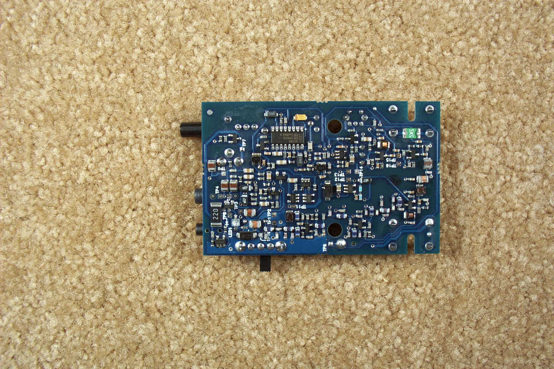
Battery Compartment PCB Top PCB Bottom
Parts List/Tune Up Info
2.1033(c)(8) Question: The dc voltages applied to and dc currents into the several elements of the final radio frequency amplifying device for normal operation over the power range. The RF Power Amp stage operates from a 2.15V regulated supply and the typical current is 15 to 20mA. • 2.1033(c)(9) Question: Tune-up procedure over the power range, or at specific operating power levels. All manufacturing tuning performed on Automated Test Equipment. No manual tune up procedure is used.
RF Exposure Info
5473-A Clouds Rest * Mariposa, CA 95338 * PH (209) 966-5240 * Fax (209) 742-6133 WORLDWIDE EMC – COMMERCIAL * INDUSTRIAL * MEDICAL * MILITARY * AVIONICS BREA, CA * FREMONT, CA *HOLLISTER, CA* MARIPOSA, CA *HILLSBORO, OR*TILLAMOOK, OR*REDMOND, WA Maximum Permissible Exposure Calculations Date of Report: Calculations prepared for: Phonic Ear, Inc. 3880 Cypress Drive Petaluma, CA. 94954-7600 Calculations prepared by: Matthew Pettersen CKC Laboratories, Inc. 5473A Clouds Rest Road Mariposa, CA 95338 Model Number: Easy Listener-2 330- 216MHz FCC Identification: Pending Fundamental Operating Frequency (MHz): 216.025 - 216.975 Maximum Rated Output Power: 20.00dBm Measured Output Power: 15.14dBm Power Output and Operating Frequency Information used for these calculations were from: CKC Laboratories, Test Report # MPE Limit in accordance with 1.1310(b): Limits for general population/uncontrolled exposure MPE Limit = 0.2 (mW/cm 2 ) EIRP (mW) Distance (cm) Power Density (mW/cm 2 ) Result 32.66 3.60 0.2 Pass 2 2 4 )/( d EIRP cmmWDensityPower π = Given: EIRP in mW and d in cm EIRP calculated with antenna gain. Max Rated Output Power based on 95.639(e) for LPRS stations Under normal operating conditions, the antenna is designed to maintain a separation distance of 3.60cm from all persons. As can be seen from the MPE results, this device passes the limits specified in 1.1310 at a distance of 3.60cm and at an output power of 32.66mW.
RF Exposure Info
5473-A Clouds Rest * Mariposa, CA 95338 * PH (209) 966-5240 * Fax (209) 742-6133 WORLDWIDE EMC – COMMERCIAL * INDUSTRIAL * MEDICAL * MILITARY * AVIONICS BREA, CA * FREMONT, CA *HOLLISTER, CA* MARIPOSA, CA *HILLSBORO, OR*TILLAMOOK, OR*REDMOND, WA Regarding Phonic Ear FCC ID BRG330T216 This equipment does not fall under Subparts H and I of Part 95 and is therefore categorically excluded from routine environmental evaluation for RF exposure as per Part 2.1093c
Test Report
Page 1 of 43 Report No.: FC04-012B ADDENDUM TO PHONIC EAR TEST REPORT FC04-012A FOR THE BODY WORN TRANSMITTER, EASY LISTENER-2 330T-216 MHZ FCC PART 95 AND RSS 210 COMPLIANCE DATE OF ISSUE: MARCH 24, 2004 PREPARED FOR: Phonic Ear 3880 Cypress Drive Petaluma, CA 94954-7600 PREPARED BY: Mary Ellen Clayton CKC Laboratories, Inc. 5473A Clouds Rest Mariposa, CA 95338 P.O. No.:p112359 W.O. No.:81765 Date of test:January 20 – February 10, 2004 Report No.: FC04-012B This report contains a total of 43 pages and may be reproduced in full only. Partial reproduction may only be done with the written consent of CKC Laboratories, Inc. The results in this report apply only to the items tested, as identified herein. Page 2 of 43 Report No.: FC04-012B TABLE OF CONTENTS Administrative Information..............................................................................................3 Summary of Results.........................................................................................................4 Comparison Matrix...........................................................................................................4 Conditions for Compliance..............................................................................................4 Approvals.........................................................................................................................5 Equipment Under Test (EUT) Description......................................................................6 Equipment Under Test.....................................................................................................6 Peripheral Devices............................................................................................................6 Measurement Uncertainty................................................................................................6 Temperature and Humidity During Testing.....................................................................7 FCC 2.1033(c)(3) User’s Manual.....................................................................................7 FCC 2.1033(c)(4) Type of Emissions..............................................................................7 FCC 2.1033(c)(5) Frequency Range................................................................................7 FCC 2.1033(c)(6) Operating Power.................................................................................7 FCC 2.1033(c)(7) Maximum Power Rating.....................................................................7 FCC 2.1033(c)(8) DC Voltages.......................................................................................7 FCC 2.1033(c)(9) Tune-Up Procedure.............................................................................7 FCC 2.1033(c)(10) Schematics and Circuitry Description..............................................7 FCC 2.1033(c)(11) Label and Placement.........................................................................7 FCC 2.1033(c)(12) Submittal Photos...............................................................................7 FCC 2.1033(c)(13) Modulation Information...................................................................7 FCC 2.1033(c)(14)/2.1046/95.637 - RF Power Output (Antenna Conducted)................8 FCC 2.1033(c)(14)/2.1046/95.1013 - RF Power Output (OATS)...................................11 FCC 2.1033(c)(14)/2.1047(b) - Audio Frequency Response...........................................14 FCC 2.1033(c)(14)/2.1047(b) - Modulation Limiting Response.....................................16 FCC 2.1033(c)(14)/2.1049(i)/95.633 Occupied Bandwidth............................................18 FCC 2.1033(c)(14)/2.1051/95.635(c) - Spurious Emissions at Antenna Terminal.........21 FCC 95.635 - Emissions Mask.........................................................................................26 FCC 2.1033(c)(14)/2.1053/95.635(c) - Field Strength of Spurious Radiation................29 FCC 2.1033(c)(14)/2.1055/95.629 - Frequency Stability................................................34 FCC RSS 210 - Field Strength of Spurious Radiation.....................................................36 RSS 210 6.2.2 - Emissions Mask D.................................................................................41 Page 3 of 43 Report No.: FC04-012B ADMINISTRATIVE INFORMATION DATE OF TEST:January 20 – February 10, 2004 DATE OF RECEIPT:January 20, 2004 PURPOSE OF TEST:To demonstrate the compliance of the Body Worn Transmitter, Easy Listener-2 330T-216 MHz with the requirements for FCC Part 95 and RSS 210 devices. Addendum A is to revise the OATS RF power data sheets and revise the test conditions to the OATS testing. Addendum B is to revise the OATS RF power data table and the operating power on page 7. TEST METHOD:FCC Part 95, RSS 210 and TIA/EIA 603 FREQUENCY RANGE TESTED:20 MHz - 2000 MHz MANUFACTURER:LeeMah Electronics, Inc. Fremont, CA REPRESENTATIVE:Jeff Davies TEST LOCATION:CKC Laboratories, Inc. 480 Los Viboras Road, Hollister, CA 95023 1120 Fulton Place, Fremont, CA 94539 Page 4 of 43 Report No.: FC04-012B SUMMARY OF RESULTS As received, the Phonic Ear Body Worn Transmitter, Easy Listener-2 330T-216MHz was found to be fully compliant with the following standards and specifications: United States ÿ FCC Part 95 FCC Site Filing No. 90479 & 90477 Canada RSS-210 using: ÿ FCC Part 95 Canada Site Filing No. IC 3171-B & 3082-B COMPARISON MATRIX Canadian Standard Canadian Section FCC Standard FCC Section Test Description RSS 2105.547CFR15.203Antenna Connector Requirements RSS 2106.2.2(L2)47CFR95.629Two Way Voice Prohibited RSS 2106.2.2(L2)47CFR95.637Peak Output Power Requirements (100mW) RSS 2106.2.2(L2)47CFR95.1013 Peak Output Power Requirements FCC: 100mW ERP Canada: 160mW ERP RSS 2106.2.2(L2)N/AN/ACanada Channel 13 Advisory RSS 2106.2.2(L2)47CFR95.633Emission Bandwidth RSS 2106.2.2(L2)47CFR95.635Emission Mask RSS 2106.2.2(L2)N/AN/A Instrumentation for Mask (Pe…
Text truncated - open the document above for the full version.
Test Setup Photos
RF Antenna Port Test Setup PHOTOGRAPH SHOWING RADIATED EMISSIONS Radiated Emissions - Front View PHOTOGRAPH SHOWING RADIATED EMISSIONS Radiated Emissions - Back View 2.1047 Test Setup Direct Connect Temperature Setup
Contact Information
Applicant
Mr. Michael Gibbs(Regulatory Affairs & QMS Manager)
Technical Contact
CKC Laboratories, Inc.Mary Ellen Clayton
[email protected]209-966-5240
5473-A Clouds Rest · Mariposa, California · United States
Non-Technical Contact
CKC Laboratories, Inc.Mary Ellen Clayton
[email protected]209-966-5240
Test Firm
CKC Laboratories, Inc.Steve Behm
Technical Specifications
| # | Rule Parts | Frequency Range | Power Output | Emission | Tolerance |
|---|---|---|---|---|---|
| 1 | 95G | 216.025 MHz - 216.975 MHz | 33.70 mW | 50K0F3E | 20.8392000000 ppm |
Other Applications from Phonic Ear, Inc.

BRG-T21
Mar 13, 2007Wireless Accessory for Hearing Aid
Equipment Class
TNT - Licensed Non-Broadcast Transmitter Worn on Body
BRG340T-216
Nov 10, 2005Portable Body Worn FM Transmitter
Equipment Class
TNT - Licensed Non-Broadcast Transmitter Worn on Body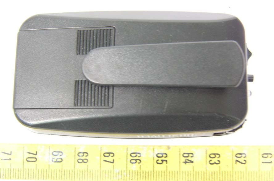
BRGPEPZT003
Oct 12, 2005Observer
Equipment Class
DSC - Part 15 Security/Remote Control Transmitter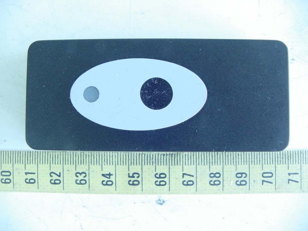
BRGPZO1
Apr 18, 2005Wireless Doorbell
Equipment Class
DSC - Part 15 Security/Remote Control Transmitter
BRGDETECTDOOR
Mar 14, 2005Wireless Doorbell
Equipment Class
DSC - Part 15 Security/Remote Control Transmitter