BRG560T
Phonic Ear, Inc.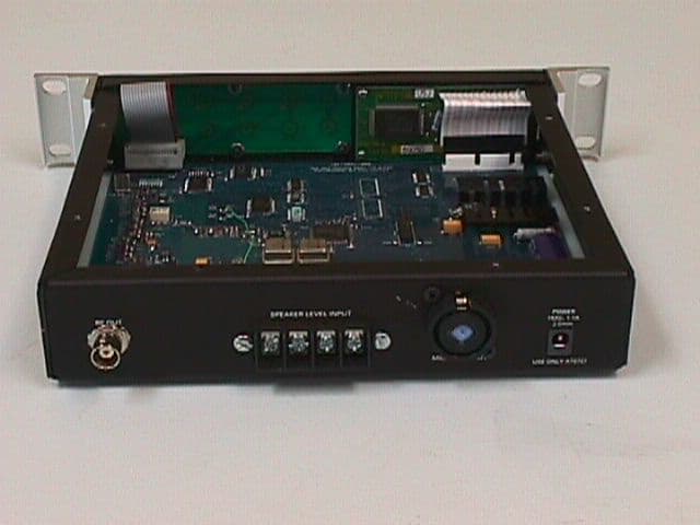
Click to zoom
Application Details
- Equipment Class
- GAT - Part 15 Auditory Assistance Device (Transmitter)
- Date of Grant
- Nov 07, 1999
- Application Purpose
- Original Equipment
- Date of Application
- Sep 20, 1999
- Frequency Range
- 75.20000000 - 76.00000000
- Company
- Phonic Ear, Inc.
- Country
- United States
Documents & Files
Document Text
Text extracted from the exhibit documents filed with the FCC. Open a document above to read the original.
Users Manual
ONWAVE USER GUIDE 1) ANTENNA MOUNTING 1A) Standard Mounting the Whip Antenna, AT0777 • Attach the antenna by screwing antenna onto the back of the unit (connector has left- handed thread). 1B) Remote Mounting the Whip Antenna. (Requires the Antenna Ground Plane, AT0775 or AT0776) • Installing the transmitter in a metal sound room or metal racks may confine the signal. Remote installing the antenna outside of the sound room provides optimum coverage (i.e., near the seats), while keeping your transmitter convenient to access. • Remote mounting the antenna eliminates potential interference between the RF signal and other sensitive electronic devices in the audio rack. 1) Attach the antenna to the ground plane jack that’s closest to the middle of the ground plane. 2) U.S. FM systems are required by the FCC to feature non-standard connectors (unique to Phonic Ear) on the transmitter. Remote mounting the antenna requires the Phonic Ear ground plane kit that includes the non-standard cable (AT0776). Contractors using their own cable (RG58/U 50-ohm coaxial cables) to make custom cable lengths can order the ground plane with the non-standard connector kit (AT0775). 3) Attach the cable to the other jack on the ground plane. 4) Plug the free end of the cable into the RF OUT jack on the back of the transmitter, and secure the cable away from foot traffic. 5) Choose a location where the antenna will “see” the entire seating arrangement and test the system to make sure there aren’t any dead spots in the listening environment before securing the ground plane permanently. 6) Secure the ground plane by attaching screws through the two holes provided and mount it on a wall or a ceiling (we recommend a vertical orientation). The ground plane can also be placed on a tabletop. 1D) Large Area Antenna Mounting • Required coverage radius is greater than 60m/200 ft. • Large area coverage radius of 300m/1000 ft. 1) For shipping purposes it's necessary to collapse the antenna, you will need to extend the antenna to its tuned height for best results. To extend it, loosen the two worm clamps and pull the large center section out to the black ring marked around the tube. Then tighten the lower worm clamp and extend the smaller element to the black ring. Tighten the top clamp. 2) The large area antenna comes with a mounting hole and set screw so you can mount it on a tripod (such as Radio Shack’s 1m/3ft tripod mount; Part #15-516) with a mast (such as Radio Shack’s 1.5m/5 ft mast; Part #15-842). Ground your mounting pole, tripod, or other holder to a metal surface to protect against lightning strikes. You may also hang the antenna from a railing or metal superstructure (such as in a stadium). 3) The antenna is an electrical conductor. Contact with power lines can result in death or serious injury. Do not install the antenna, supporting mast, or tower where there is any possibility of contact with a high-voltage arc from power cables or service drops. Outdoor antennas should be grounded against lightning strikes. Consult the National Electrical Code for further details. 4) Be careful not to deform or move the tuning ring around the black insulator at the antenna’s base, doing so will affect the antenna’s tuning as well as its efficiency. 5) Do not place the antenna where it would be parallel to or within six feet of any metal structure; situating the antenna in such a way will de-tune it. It’s fine, however, to place the antenna perpendicular to and beneath metal. 6) As with the standard antenna, experiment with different locations to achieve the best possible antenna placement. Make sure you place it in a location where it will “see” the entire seating arrangement. We recommend vertical orientation, upside down at maximum height. 7) US FM systems are required by the FCC to feature non-standard connectors (unique to Phonic Ear) on the transmitter. The Large Area Antenna Kit includes a non standard connector kit for use with RG-58/U 50 Ohm Coaxial Cable. There are two antenna kits to choose from. The AT0773 Low Band Antenna is used for Channels A-E (WB) or 1 –20 (NB). The AT0774 High Band Antenna is used for channels F-J (WB) or 21 –40 (NB). 8) Keep the cable length as short as possible, the maximum recommended RG58/U cable length is 30m/100 ft. If you find that your installation requires longer cable, contact our Applications Engineer Bob Mendoza at (800) 227-0735, extension 276 before purchasing a transmitter — he can help specially modify a transmitter to meet your needs. 9) Attach one end of the cable to the connector found on the large area antenna. 10) Attach the other end of the cable to the ANTENNA jack on the back of the PE560T transmitter, and secure it away from foot traffic, * Use only those antennas supplied or recommended by Phonic Ear. For help selecting an appropriate antenna, consult the ON WAVE 560T specification sheet, or call Customer Service at 800-227-0735, then press 5 (800-263-8700 in Canada 2) TRANSMITTER INSTALLATION 2A) Use the AT0780 or the AT0781 rack mount kit to install the transmitter in the audio rack or place close by the audio system. 2B) Plug the AT0757 transformer into the power jack on back of the transmitter, plug in the wall outlet, and press the power key on the front panel to turn on the unit. 2C) Connect one end of an XLR or 1/4" cable to the universal mic/line input and the opposite end to the sound system mixer. For connection to a stand-alone mic (compatible with dynamic or condenser mics, system has phantom power,12V) use an XLR cable. Select the desired input by pressing the mic/line key located on the front panel. The selection will appear on the display. To connect to speaker levels of 10 Volts RMS use the terminal block input (sum inputs) and select the line level setting on the transmitter. Using a series resistor one can accommodate higher input levels; an additional 47K Ohm resistor can be used for an input level of 20 Volts RMS and 100K Ohm resistor for 30 Volts RMS…
Text truncated - open the document above for the full version.
Cover Letter(s)
November 8, 1999- FCC ID BRG 560T Reference Number: 10540 FCC Application Processing Branch Sirs: Phonic Ear, Inc., 3880 Cypress Drive, Petaluma, CA 94954 Product – BRG 560T In reference to Section 0.459, we respectfully submit this request for confidentiality. The documents to be held in confidence with respect to the 560T include the Block Diagram, Theory of Operation, Schematic Diagram and photo of the PCB layout. We are requesting confidentiality from the FCC to preclude our competitors from obtaining proprietary information on our product Sincerely, Barb A.. Brown Director, Regulatory Affairs Phonic Ear
External Photos
GEL Report File PE9901External PhotosFCC ID BRG560T Glen Ellen Laboratories1August 9, 1999 View of the broadband antenna GEL Report File PE9901External PhotosFCC ID BRG560T Glen Ellen Laboratories2August 9, 1999 View of the front panel: GEL Report File PE9901External PhotosFCC ID BRG560T Glen Ellen Laboratories3August 9, 1999 View of the rear panel: GEL Report File PE9901External PhotosFCC ID BRG560T Glen Ellen Laboratories4August 9, 1999 View of the groundplane: GEL Report File PE9901External PhotosFCC ID BRG560T Glen Ellen Laboratories5August 9, 1999 Power Supply: GEL Report File PE9901External PhotosFCC ID BRG560T Glen Ellen Laboratories6August 9, 1999 FCC ID label location:
ID Label/Location Info
GEL Report File PE9901FCC ID LabelFCC ID BRG560T Glen Ellen Laboratories1August 9, 1999 FCC ID label drawing: GEL Report File PE9901FCC ID LabelFCC ID BRG560T Glen Ellen Laboratories2August 9, 1999 FCC ID label location:
Test Report
TEST REPORT FOR FCC PART 15 COMPLIANCE FOR PHONIC EAR INC. Prepared by Daniel C. Swann August 9, 1999 Phonic Ear Inc. Part Number PE 560T FCC Part 15.237 Intentional Radiator FCC ID BRG560T GEL Report File PE9901 GLEN ELLEN LABORATORIES 1876 London Ranch Road Glen Ellen, CA 95442 GEL Report File PE9901FCC ID BRG560T Glen Ellen Laboratories2August 9, 1999 MEASUREMENT/TECHNICAL REPORT PHONIC EAR FCC ID BRG560T This report concerns:An Original Grant Equipment type:Part 15.237 Intentional Radiator Deferred grant requested:no Transition rules per 15.37:no Report prepared by:Daniel C. Swann Glen Ellen Laboratories 1876 London Ranch Road Glen Ellen, CA 95442 (707) 996-8533 (707) 996-2803 fax Report Certified By:Daniel C. Swann_________________________ Date_________________________ GEL Report File: PE9901 GEL Report File PE9901FCC ID BRG560T Glen Ellen Laboratories3August 9, 1999 TABLE OF CONTENTS 1GENERAL INFORMATION 1.1Product Description 1.2Related Submittal and Grant 1.3Tested System Details 1.4Test Methodology 1.5Test Facility 2PRODUCT MANUAL STATEMENT 2.1FCC Statement in User Manual 3SYSTEM TEST CONFIGURATION 3.1Justification 3.2EUT Exercise Software 3.3Special Accessories 3.4Equipment Modifications 3.5Configuration of Tested System 4CONDUCTED EMISSIONS DATA 5RADIATED EMISSIONS DATA 5.1Data 5.2Field Strength Calculations 6APPENDIX 6.1 Plots of Occupied Bandwidth 6.2 List of Exhibits GEL Report File PE9901FCC ID BRG560T Glen Ellen Laboratories4August 9, 1999 1GENERAL INFORMATION 1.1Product Description The Phonic Ear Part Number PE 560T is a frequency modulated transmitter which utilizes the FCC Part 15.237 frequency bands for auditory assistance devices. The transmitter uses either a short flexible plastic covered broadband antenna, or a 6 foot Large Area tuned antenna (two differently tuned antennas are required to cover the frequency range). The short antenna was tested attached to the rear RF connector of the unit, and also tested connected with a coax cable to a small groundplane placed remotely from the transmitter. The coaxial antenna connections are made to the transmitter unit and to the antennas with a unique coupling, insuring that no other antenna than that furnished by Phonic Ear inc. will be used. Specifically, the connector used is a left hand thread TNC coaxial connector, denoted LH-TNC. The transmitter uses a standard audio input from a microphone, as used for the testing detailed in this report, or another audio source. See the User Instructions for a description of the available controls on the EUT. The product is powered by a wall-mount transformer. The internal construction is a single multi layer PC board, a front panel keyboard PC board, and a display module. The product is housed in a metal box. 1.2Related Submittal or Grant There are no related submittals or grants. GEL Report File PE9901FCC ID BRG560T Glen Ellen Laboratories5August 9, 1999 1.3Tested System Details EUT Phonic Ear Part Number PE 560T transmitter, PC Board Fab 900-7285-401. Power Supply Calrad Model 45-764, 120VAC input, 16 VAC output at 1.1 amp, with 1.9 meter unshielded cable. With the following accessories: Note: LH-TNC is a abbreviation for “Left Hand Thread TNC coaxial connector” AccessoryPE Part Number Description Short AntennaAT0777Broadband antenna with LH-TNC connector GroundplaneAT0775Antenna Groundplane, LH-TNC with connector kit GroundplaneAT0776Antenna Groundplane, LH-TNC, with LH-TNC 50 foot cable Large Area Antenna, Low Band AT0773Large Area Antenna, LH-TNC, Low Band, with connector kit Large Area Antenna, High Band AT0774Large Area Antenna, High Band, LH-TNC with connector kit Connector kitAT0778LH-TNC cable connector kit Coax CableAT0779LH-TNC cable, 50 feet long Made by: Phonic Ear Inc. 3880 Cypress Drive Petaluma, CA 94954-7600 The circuit uses various oscillators. See the Block Diagram for more information. GEL Report File PE9901FCC ID BRG560T Glen Ellen Laboratories6August 9, 1999 1.4Test Methodology The emissions tests were performed in accordance with the ANSI C63.4-1992 standard. 1.5Test Facility The Glen Ellen Laboratories open area test site and conducted measurement facility is located in Glen Ellen, California, at the street address of 1876 London Ranch Road. This site has been fully described in a report dated September 16, 1996, submitted to the FCC, and accepted in a letter dated December 4, 1996 (31040/SIT/1300F2.) Test equipment used included: 1.Hewlett Packard 8560A opt 002 spectrum analyzer, cal due 6-20-00. 2.Sonoma Instruments 317 preamplifier, 10 kHz to 2.5 GHz, cal due 3-5-00. 3.GEL BIC9414 biconical antenna, 30 MHz to 300 MHz, cal due 6-22-00. 4.GEL LPA-3 log periodic antenna, 275 MHz to 2 GHz, cal due 6-22-00. 5.Two Solar LISN's model number 8028-50-TS-24-BNC, cal due 5-09-00. 6.EMCO LISN, model number 3825/2, cal due 5-09-00. GEL Report File PE9901FCC ID BRG560T Glen Ellen Laboratories7August 9, 1999 2PRODUCT MANUAL STATEMENT 2.1FCC Statement in User Manual The following statement appears in a prominent location in the text of the user manual: NOTE: This device complies with Part 15 of the FCC Rules. Operation is subject to the following two conditions: (1) this device may not cause harmful interference, and (2) this device must accept any interference received, including interference that may cause undesired operation. Any changes or modifications made to any government approved element of this FM system, without the expressed approval of Phonic Ear Inc., in writing, could void the user's authority to operate those elements of the system. If any antenna or cordage, other than those specifically approved for use with this FM system by Phonic Ear Inc. is used, the antenna or cord must be installed by a professional and the operation of the system must be verified by the installer of the antenna or cord to comply with applicable government regulations. IMPORTANT: This product was tested for FCC compliance under conditions that included the use of shielded cables …
Text truncated - open the document above for the full version.
Test Setup Photos
GEL Report File PE9901Test SetupFCC ID BRG560T Glen Ellen Laboratories1August 9, 1999 Front of the Conducted Test Setup GEL Report File PE9901Test SetupFCC ID BRG560T Glen Ellen Laboratories2August 9, 1999 View of Back of the Conducted Test Setup GEL Report File PE9901Test SetupFCC ID BRG560T Glen Ellen Laboratories3August 9, 1999 View of the front of the radiated test setup for broadband antenna: GEL Report File PE9901Test SetupFCC ID BRG560T Glen Ellen Laboratories4August 9, 1999 View of the rear of the radiated test setup for broadband antenna: GEL Report File PE9901Test SetupFCC ID BRG560T Glen Ellen Laboratories5August 9, 1999 View of the front of the radiated test setup for groundplane: GEL Report File PE9901Test SetupFCC ID BRG560T Glen Ellen Laboratories6August 9, 1999 View of the rear of the radiated test setup for groundplane: GEL Report File PE9901Test SetupFCC ID BRG560T Glen Ellen Laboratories7August 9, 1999 View of radiated test setup for the large antenna:
Contact Information
Applicant
Mr. Michael Gibbs(Regulatory Affairs & QMS Manager)
Technical Contact
PHONIC EAR, INC.ROGER A DAVIS
[email protected]707-769-1110
3880 CYPRESS DRIVE · PETALUMA, California · United States
Non-Technical Contact
PHONIC EAR, INC.GENE STROHALLEN
[email protected]707-769-1110
Test Firm
Glen Ellen LaboratoriesDaniel Swann
Technical Specifications
| # | Rule Parts | Frequency Range | Power Output | Tolerance |
|---|---|---|---|---|
| 3 | 15C | 75.2 MHz - 76 MHz | - | % |
Other Applications from Phonic Ear, Inc.

BRG-T21
Mar 13, 2007Wireless Accessory for Hearing Aid
Equipment Class
TNT - Licensed Non-Broadcast Transmitter Worn on Body
BRG340T-216
Nov 10, 2005Portable Body Worn FM Transmitter
Equipment Class
TNT - Licensed Non-Broadcast Transmitter Worn on Body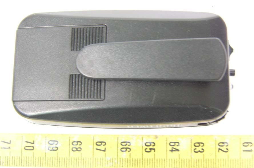
BRGPEPZT003
Oct 12, 2005Observer
Equipment Class
DSC - Part 15 Security/Remote Control Transmitter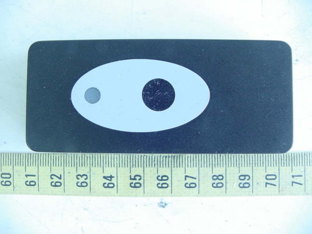
BRGPZO1
Apr 18, 2005Wireless Doorbell
Equipment Class
DSC - Part 15 Security/Remote Control Transmitter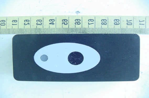
BRGDETECTDOOR
Mar 14, 2005Wireless Doorbell
Equipment Class
DSC - Part 15 Security/Remote Control Transmitter