BZ5DTR10SCDigital Television Translator
Larcan Inc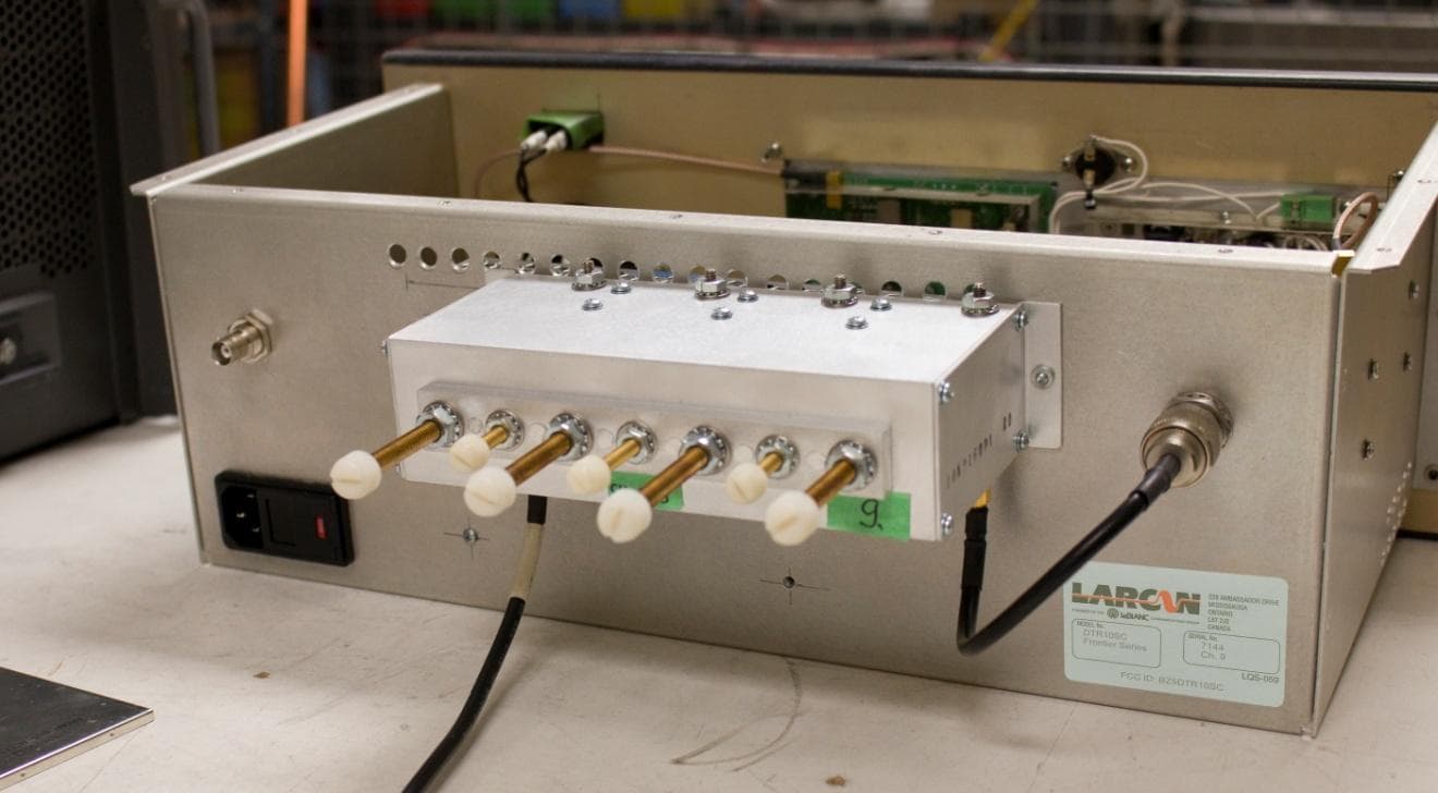
Click to zoom
Application Details
- Equipment Class
- TBC - Licensed Broadcast Station Transmitter
- Date of Grant
- Jun 16, 2014
- Application Purpose
- Original Equipment
- Date of Application
- Feb 13, 2014
- Equipment Note
- Digital Television Translator
- Frequency Range
- 174.00000000 - 216.00000000
- Company
- Larcan Inc
- Country
- Canada
Documents & Files
Document Text
Text extracted from the exhibit documents filed with the FCC. Open a document above to read the original.
Users Manual
GENERAL INFORMATION AND INSTALLATION PUB14-01Rev 0 April 10, 2014 i DTR10SC General Information & Installation CONTENTS 1 GENERAL INFORMATION ...........................................................................................................................................1 2 GROUNDING/EARTHING .............................................................................................................................................2 3 LIGHTNING AND OTHER TRANSIENT PROTECTION .........................................................................................4 4 ABOUT POWER WIRING ..............................................................................................................................................5 5 VENTILATION/AIR CONDITIONING INFORMATION ..........................................................................................6 6 FIRE PROTECTION ........................................................................................................................................................7 7 UNPACKING.....................................................................................................................................................................8 8 TRANSMITTER EXTERNAL INTERLOCK CONNECTIONS ................ERROR! BOOKMARK NOT DEFINED. 9 FIRST-TIME, ON-SITE TRANSMITTER START-UP PROCEDURE ......................................................................9 GENERAL INFORMATION AND INSTALLATION PUB14-01Rev 0 April 10, 2014 1 DTR10SC General Information & Installation 1 GENERAL INFORMATION One of the keys to a successful installation is meticulous planning and adequate allowances for task times. Allow sufficient time to consider and plan all aspects of the installation, including the building, whether new or existing. Once determined allow for realistic time spans for the building construction or renovation, equipment transportation and installation, and final commissioning. A low powered transmitter will require a very short time span for these activities, while high powered equipment could require many months. For more information, contact our Applications Engineering Manager who is available and able to guide you. Your consulting engineer is also a good source of information. Both these persons would be familiar with technical aspects of the proposed installation. Applications Engineering support offered by LARCAN includes technical information, recommendations on vendor products when requested, and advice on project task considerations and time span estimation. This assistance is available upon request. Although general application information is included in this manual, it is important that specific system layouts be prepared and that locations of cabinets and RF equipment, such as RF patching or switching equipment, are determined together with the routing of the transmission line, AC power (Mains) feeds and other wiring, grounding (earthing), and ventilation air ducting. Lightning protection should be considered early in the planning process, because a good building layout can offer significant benefit. The DTR10SC series transmitter is a single chassis transmitter intended for rack mounting in a standard 19" cabinet. Since this type of product is often supplied for standby use or in unattended isolated site locations and therefore it is anticipated that any rack mounting arrangement pre-exists and is supplied by the customer. The installation of the DTR10SC must take into account ventilation considerations as outlined further in this document. That said, please note the ventilation openings of the cabinet should be fitted with air filters, to help the transmitter components remain clean. Also because of the small size of this product a tabletop style of cabinet can be used and may be preferred. Due consideration must be given to ventilation, as proper cooling ensures the longest equipment lifetime. Basic cooling information is provided, but if a higher powered transmitter is also on site, an experienced air conditioning contractor should be consulted. Ensure that sufficient space is available both in front and rear of all cabinets and other equipment to permit easy access while equipment is being moved around, and to enhance accessibility for future maintenance. A minimum 90 to 100cm (about 3 to 3½ feet) of clearance is recommended to allow access for a technician and test equipment, but you may need more clearance for other reasons or for the lifting devices sometimes used during installations. You may wish to consult local equipment rental agencies for dimensions of their available lifting apparatus; the required clearance is one of the "planning" items to be considered. All cabinets should be level. An uneven floor surface can distort the sheet metal frames of many cabinets so that door latches will not operate properly. GENERAL INFORMATION AND INSTALLATION PUB14-01Rev 0 April 10, 2014 2 DTR10SC General Information & Installation 2 GROUNDING/EARTHING For safety, it is important that grounding conductors of adequate size be used to connect the transmitter (and other) cabinet(s) to the station "technical ground" point. The following notes are supplied as a guide to grounding at full- service transmitter installations but are useful for all cases. The metal bulkhead plate through which all circuits and coax lines to and from the tower will pass, makes an excellent technical ground because it will be connected with one or two, 150mm wide x 1.5mm thick copper straps to the tower ground system. One method is that in which copper bar 75 or 100mm wide and the same thickness as the floor tile is laid under transmitter and other cabinets for grounding. Each cabinet rack or tabletop cabinet is then connected with 1.5mm copper strap or automotive starter cable to the copper ground bar. The copper bar in turn connects to the metal bulkhead plate. Alternatively, copper strap can be laid in a grounded overhead cable tray. Indoor…
Text truncated - open the document above for the full version.
Users Manual
PUBLICATION TSM 20-399 TECHNICAL MANUAL 10 WATT VHF AMPLIFIER FOR FRONTIER SERIES DIGITAL TV TRANSMITTER/TRANSLATOR LARCAN INC. 228 AMBASSADOR DRIVE MISSISSAUGA, ONTARIO CANADA L5T 2J2 PHONE: (905) 564-9222 FAX: (905) 564-9244 Rev 0 Feb 2014 TSM 20-399 Rev 0, Feb 2014 1 10W VHF Amplifier CONTENTS 1 GENERAL .......................................................................................................................................................................... 3 1.1 SAFETY NOTICES .......................................................................................................................................................... 3 1.1.1 Beryllium Oxide Warning .................................................................................................................................... 3 1.1.2 Other Toxic Materials .......................................................................................................................................... 3 1.1.3 Dangerous Voltages ............................................................................................................................................. 3 1.1.4 Switch to Safety .................................................................................................................................................... 4 1.2 STATIC AWARENESS ..................................................................................................................................................... 5 1.3 TRADEMARK INFORMATION .......................................................................................................................................... 6 1.4 PRODUCTION CHANGES ................................................................................................................................................ 6 2 INTRODUCTION.............................................................................................................................................................. 7 2.1 AMPLIFIER CHAIN ......................................................................................................................................................... 7 3 MASK FILTER AND OUPTPUT .................................................................................................................................... 8 3.1 HELICAL RESONATOR BANDPASS FILTER ...................................................................................................................... 8 3.2 LOW POWER FILTER FOR HIGH BAND ........................................................................................................................... 9 3.3 LOW PASS AND NOTCH FILTER FOR LOW BAND ............................................................................................................ 9 3.4 RF DIRECTIONAL COUPLER ......................................................................................................................................... 10 4 RF POWER AMPLIFIER AND HEATSINK ASSEMBLY ........................................................................................ 18 4.1 PREAMPLIFIER ............................................................................................................................................................. 18 4.2 OUTPUT AMPLIFIER ..................................................................................................................................................... 18 5 METERING AND CONTROL ....................................................................................................................................... 24 5.1 SYSTEM ...................................................................................................................................................................... 24 5.2 RF DETECTORS ........................................................................................................................................................... 24 5.3 RF METERING BOARD CALIBRATION .......................................................................................................................... 24 5.3.1 Forward Power Meter Calibration - Zero Adjust .............................................................................................. 24 5.3.2 Reflected Power Meter Calibration - Zero Adjust ............................................................................................. 24 5.3.3 Forward Power Calibration .............................................................................................................................. 25 5.3.4 Reflected Power Calibration .............................................................................................................................. 25 TSM 20-399 Rev 0, Feb 2014 2 10W VHF Amplifier LIST OF FIGURES Figure 1 Bandpass Filter Response ...........................................................................................................................8 Figure 2 Bandpass Filter Schematic ...........................................................................................................................9 Figure 3 RF Directional Coupler Schematic .............................................................................................................11 Figure 4 Generic Helical Resonator Bandpass Filter Assembly ..............................................................................12 Figure 5: Filter Schematic .........................................................................................................................................13 Figure 6 Low Band Bandpass and Notch Filter Assembly ........................................................................................14 Figure 7 Low Band Bandpass and Notch Filter Schematic .....................................................................................15 Figure 8 RF Directional Coupler ...............................................…
Text truncated - open the document above for the full version.
Cover Letter(s)
LARCAN U.S. Tel: 1-303-665-8000 Fax: 1-303-673-9900 Canada Tel: 1-905-564-9222 Fax: 1-905-564-9244 www.larcan.com Email: [email protected] 228 Ambassador Drive Mississauga ON Canada L5T 2J2 April 16, 2014 Edna Prado Office of Engineering and Technology Re: FCC ID BZ5DTR10SC Correspondence Reference number 45621 With regards to the missing installation and operations manual for this product, please find attached our publication: “PUB14-01_Frontier DTR10SCG2 Installation_Rev0.pdf” detailing the installation and first turn-on procedure. This product is intended for operation by personnel with minimal technical abilities, and therefore its operation is intended to be as plug-and-play as possible. Also, in regards to the internal photographs, I have included a more comprehensive photograph with details illustrated. I apologize; the previous photograph detailed only the power amplifier portion of the product. Should you require additional pictures please let me know. If there is anything else you need please do not hesitate to contact me. Sincerely, John Tremblay V. P. Engineering
Cover Letter(s)
LARCAN U.S. Tel: 1-303-665-8000 Fax: 1-303-673-9900 Canada Tel: 1-905-564-9222 Fax: 1-905-564-9244 www.larcan.com Email: [email protected] 228 Ambassador Drive Mississauga ON Canada L5T 2J2 May 14, 2014 Edna Prado Office of Engineering and Technology Re: FCC ID BZ5DTR10SC Correspondence Reference number 45761 With regards to the missing schematic diagrams for this product, please find attached our publication: “TSM20-399 Frontier 10W VHF.pdf” service manual which includes the schematics and circuit description as well as a separate file/document with only the schematics. This information was inadvertently omitted from the original application. I apologize for any inconvenience this may have caused. If there is anything else you need please do not hesitate to contact me. Sincerely, John Tremblay V. P. Engineering
Cover Letter(s)
LARCAN U.S. Tel: 1-303-665-8000 Fax: 1-303-673-9900 Canada Tel: 1-905-564-9222 Fax: 1-905-564-9244 www.larcan.com Email: [email protected] 228 Ambassador Drive Mississauga ON Canada L5T 2J2 June 13, 2014 Evelyn Cherry Office of Engineering and Technology Re: FCC ID BZ5DTR10SC Correspondence Reference number 45910 thru 45913 With regards to the request for confidentiality for the 4 exhibits: “Internal Photos, Service Manual, Schematics, Schematics”, LARCAN withdraws its request for confidentiality on these items. It was initially requested for marketing reasons more than for technical reasons and is no longer required. I hope that this will cancel the requirement for extra fees in this regard. If there is anything else you need please do not hesitate to contact me. Sincerely, John Tremblay V. P. Engineering
External Photos
BZ5DTR10SC Application for FCC Certification 10 Watt Digital Television Translator Exterior Photo Front Rear (includes Simple mask filter)
ID Label/Location Info
BZ5DTR10SC Application for FCC Certification 10 Watt Digital Television Translator FCC Label/Label Location
Internal Photos
BZ5DTR10SC Application for FCC Certification 10 Watt Digital Television Translator Interior Photo of RF Amplifier (Supplementary)
Operational Description
BZ5DTR10SC Application for FCC Certification 10 Watt Digital Television Translator Operational Description: This application requests certification for a 10 Watt Digital Television Translator. The intended use of this digital translator is to rebroadcast a television relay station or other legal source of ATSC digital television signal. The DTR10SC is a solid state digital regenerative translator designed to receive over-the- air ATSC signals, converting the RF signal to baseband digital format, processing the signal to eliminate noise, and then re-modulating, converting to the new broadcast channel, amplifying and filtering the signal before it is applied to the transmit antenna. The receive section of the translator and the output modulation format conform to FCC Part 73.682(d), ATSC Digital Television Standards. The DTR10SC consists of two modules; a front-end digital Translator unit the REGEN unit, which serves to receive, process and re-modulate the signal, and a 10W output amplifier, complete with Mask Filter. The unit is cooled through natural convection. No cooling fans are used. The translator meets all FCC requirements for both the simple emissions mask and the stringent emissions mask. The output filter and final amplifier frequency response provides more than 85dB of attenuation within the GPS Frequency bands (1164-1240 MHz and 1559-1610 MHz). Testing results shown in this document were conducted on channel 9 (189 MHz center frequency), except for frequency stability tests which were conducted on channel 7. These test results are representative of performance on any channel in the VHF broadcast spectrum. Wiring, shielding and construction are in accordance with accepted principles of good engineering practice. The translator’s construction is such that all hazardous components are enclosed or protected against accidental contact by operating personnel.
Parts List/Tune Up Info
BZ5DTR10SC Application for FCC Certification 10 Watt Digital Television Translator Schematics/ Tune-up Procedure/Active Devices: Schematics: Schematics for each of the assemblies may be found as figures in their respective PUBs. Tuneup Procedure: The transmitter amplifier, its metering and protection circuitry is completely broadband across the respective band of operation. A transmitter configured for VHF Band III will cover all channels within this band with no need for adjustments (except for replacement of the output mask filter). Similarly, a transmitter configured for VHF Band I will cover all channels within this band. The output devices are the same for both bands of operation. The output filter must be retuned or replaced with a new filter tuned as per the frequency response sweeps attached. BZ5DTR10SC Application for FCC Certification 10 Watt Digital Television Translator Parts List and Tune-up Procedure Mask Filter: Bandpass Response (typical – shown for 497MHz f c ) BZ5DTR10SC Application for FCC Certification 10 Watt Digital Television Translator Parts List and Tune-up Procedure Mask Filter: Return loss (typical – shown for 497MHz f c ) BZ5DTR10SC Application for FCC Certification 10 Watt Digital Television Translator Active Devices List: ID Component Description Rev Qty UM Total 11A2903G2 PCB IPA VHF ENCLOSED DUAL MRFE6VS25N C1 100B-102-JT50X CAP 1nF 50V 5% SOLDER NICEL BARRIER 1 EA 1 C2 100B-102-JT50X CAP 1nF 50V 5% SOLDER NICEL BARRIER 1 EA 1 C3 100B-2R7-BT500X CAP 2.7pF 500V +/-0.1pF SOLDER NICEL BARRIER 1 EA 1 C4 100B-2R7-BT500X CAP 2.7pF 500V +/-0.1pF SOLDER NICEL BARRIER 1 EA 1 C5 100B-102-JT50X CAP 1nF 50V 5% SOLDER NICEL BARRIER 1 EA 1 C6 100B-102-JT50X CAP 1nF 50V 5% SOLDER NICEL BARRIER 1 EA 1 C7 C3225C0G2A153J125AA TDK 15nF (15000pF)100V 5% 1 EA 1 C8 C3225C0G2A153J125AA TDK 15nF (15000pF)100V 5% 1 EA 1 C9 0805CG102K9B CAP 1nF 50V 10% 0805 NPO 1 EA 1 C10 0805CG102K9B CAP 1nF 50V 10% 0805 NPO 1 EA 1 C11 GRM2195C2A102JA01D CAP 1nF 100V 5% 0805 NPO 1 EA 1 C12 12101C103KAT CAP 10nF 100V AVX 1 EA 1 C13 C5750X7R2A475K CAP 4.7uF 100V 10% 5X5.7mm X7R TDK 1 EA 1 C14 AFK107M63G24T-F CAP 100u 63V 20% SM ELECTROLYTIC 1 EA 1 C15 08052R473K0B CAP 47nF 100V 10% 0805 1 EA 1 C16 0805CG102K9B CAP 1nF 50V 10% 0805 NPO 1 EA 1 C17 0805CG102K9B CAP 1nF 50V 10% 0805 NPO 1 EA 1 C18 0805CG102K9B CAP 1nF 50V 10% 0805 NPO 1 EA 1 C19 0805CG102K9B CAP 1nF 50V 10% 0805 NPO 1 EA 1 C20 0805CG102K9B CAP 1nF 50V 10% 0805 NPO 1 EA 1 L1 1008CS-470XJLB IND 47nH 5% 2510 1 EA 1 L2 1008CS-470XJLB IND 47nH 5% 2510 1 EA 1 L3 HA4035-AL IND 330nH 2% 1812 850mA COILCRAFT 1 EA 1 L4 HA4035-AL IND 330nH 2% 1812 850mA COILCRAFT 1 EA 1 L5 2743021447 BEAD SM VHF 9.6mm FAIR-RITE 1 EA 1 Q1 MRFE6VS25NR1 TRANSISTOR VHF 25W 50V N-CH MOSFET 1 EA 1 Q2 MRFE6VS25NR1 TRANSISTOR VHF 25W 50V N-CH MOSFET 1 EA 1 Q3 MMBT2484LT1G TRANSISTOR NPN SWITCHING 1 EA 1 Q4 MMBT2484LT1G TRANSISTOR NPN SWITCHING 1 EA 1 Q5 MMBT2907ALT1G TRANSISTOR PNP 1 EA 1 Q6 BCP56 TRANSISTOR NPN 1AMP MKG"BH-10" Infineon 1 EA 1 U1 MC78L05ACD VOLTAGE REGULATOR 5V 100mA SOIC-8 1 EA 1 R1 9C12063A15R0JL RES 15R 1/4W 5% 1206 1 EA 1 R2 9C12063A15R0JL RES 15R 1/4W 5% 1206 1 EA 1 R3 3224W-1-103E RES 10K BOURNS 1 EA 1 R4 3224W-1-103E RES 10K BOURNS 1 EA 1 BZ5DTR10SC Application for FCC Certification 10 Watt Digital Television Translator R5 9C08052A1000JL RES 100R 1/10W 5% 0805 1 EA 1 R6 9C08052A1002JL RES 10k 1/4 W 5% 0805 1 EA 1 R7 9C08052A1002JL RES 10k 1/4 W 5% 0805 1 EA 1 R8 9C08052A2002JL RES 20k 1/10W 5% 0805 1 EA 1 R9 9C08052A1002JL RES 10k 1/4 W 5% 0805 1 EA 1 R10 9C08052A1002JL RES 10k 1/4 W 5% 0805 1 EA 1 R11 9C08052A1001JL RES 1k 1/10W 5% 0805 1 EA 1 R12 9C08052A2002JL RES 20k 1/10W 5% 0805 1 EA 1 R13 9C12063A3301JL RES 3.3k 1/4W 5% 1206 1 EA 1 R14 9C08052A1201JL RES 1.2k 1/10W 5% 0805 1 EA 1 R15 9C08052A1301JL RES 1.3k 1/10W 5% 0805 1 EA 1 R16 9C08052A2201JL RES 2.2k 1/10W 5% 0805 1 EA 1 R17 NTHS-1206-N0147K RES 47K NTC THERMISTOR 1 EA 1 R18 9C08052A2002JL RES 20k 1/10W 5% 0805 1 EA 1 R19 9C08052A3301JL RES 3.3k 1/10W 5% 0805 1 EA 1 R20 ERJ-12ZYJ510U RES 51R 5% 1/2W 1 EA 1 R21 FT10517N0050JBK TERMINATION 1 EA 1 R22 9C08052A1003JL RES 100k 1/10W 5% 0805 1 EA 1 R23 9C08052A1003JL RES 100k 1/10W 5% 0805 1 EA 1 HY1 PSCQ-2-250 HYBRID HIGH BAND 1 EA 1 HY2 IPP-7084 HYBRID 3DB CPLR 176-220MHz 200W 1 EA 1 T1- T4 2861001502 FERRITE BEAD 2HOLE 61MATL FAIR-RITE 6 EA 6 T1- T4 D260-4118-0000 COAX 25OHM FLEXIBLE 75MIL_OD MICRODOT 1 EA 1 CR1 MMBD7000LT1G DIODE DUAL GENERAL PURPOSE 1 EA 1 CR2 MMBD7000LT1G DIODE DUAL GENERAL PURPOSE 1 EA 1 LS150-48 Power Supply ID Component Description Rev Qty UM Total 20B1235G10 Metering Board C1 630-09472 CAP 4.7nF 100V CERAMIC 1 EA 1 C2 630-09472 CAP 4.7nF 100V CERAMIC 1 EA 1 C3 681-10689 CAP 68p 100V CERAMIC 1 EA 1 C4 681-10689 CAP 68p 100V CERAMIC 1 EA 1 C7 344-15474 CAP 470nF 63V FILM SEE 372-21474 1 EA 1 C8 344-21104 CAP 100nF 100V 10% FILM 344-25104 1 EA 1 C9 TAP2.2M16 CAP 2u2 16V TANT 1 EA 1 C10 630-09472 CAP 4.7nF 100V CERAMIC 1 EA 1 CR1 HP5082-2800 DIODE SEE IN5711 1 EA 1 CR2 HP5082-2800 DIODE SEE IN5711 1 EA 1 BZ5DTR10SC Application for FCC Certification 10 Watt Digital Television Translator CR3 HP5082-2800 DIODE SEE IN5711 1 EA 1 CR4 HP5082-2800 DIODE SEE IN5711 1 EA 1 U1 LM358N IC OP AMP 1 EA 1 U2 LM358N IC OP AMP 1 EA 1 U3 LM358N IC OP AMP 1 EA 1 Q1 MPS8598 TRANSISTOR PNP GEN PURP 1 EA 1 Q2 MPS8598 TRANSISTOR PNP GEN PURP 1 EA 1 R1 3R152P911J RES 910R 1/4W 5% 1 EA 1 R2 3R152P510J RES 51R 1/4W 5% 1 EA 1 R3 3R152P911J RES 910R 1/4W 5% 1 EA 1 R4 3R152P510J RES 51R 1/4W 5% 1 EA 1 R5 3R152P472J RES 4.7k 1/4W 5% 1 EA 1 R6 3R152P472J RES 4.7k 1/4W 5% 1 EA 1 R7 3R152P472J RES 4.7k 1/4W 5% 1 EA 1 R8 3R152P472J RES 4.7k 1/4W 5% 1 EA 1 R11 3R152P275J RES 2.7M 1/4W 5% 1 EA 1 R12 3R152P275J RES 2.7M 1/4W 5% 1 EA 1 R13 3R152P101J RES 100R 1/4W 5% 1 EA 1 R17 3R152P122J RES 1.2k 1/4W 5% 1 EA 1 R18 3329H-1-102 POT 1K 1 EA 1 R19 3R152P122J RES 1.2k 1/4W 5% 1 EA 1 R20 3329H-1-102 POT 1K 1 EA 1 R21 3R152P104J RES 100k 1/4W 5% 1 EA 1 R23 3R152…
Text truncated - open the document above for the full version.
Schematics
TSM 20-399 Rev 0, Feb 2014 12 10W VHF Amplifier Figure 4 Generic Helical Resonator Bandpass Filter Assembly TSM 20-399 Rev 0, Feb 2014 13 10W VHF Amplifier Figure 5: Filter Schematic TSM 20-399 Rev 0, Feb 2014 14 10W VHF Amplifier Figure 6 Low Band Bandpass and Notch Filter Assembly TSM 20-399 Rev 0, Feb 2014 15 10W VHF Amplifier Figure 7 Low Band Bandpass and Notch Filter Schematic TSM 20-399 Rev 0, Feb 2014 16 10W VHF Amplifier Figure 8 RF Directional Coupler TSM 20-399 Rev 0, Feb 2014 17 10W VHF Amplifier Figure 9 Low Band Coupler PC Board Assembly TSM 20-399 Rev 0, Feb 2014 19 10W VHF Amplifier Figure 10: Preamplifier Assembly TSM 20-399 Rev 0, Feb 2014 20 10W VHF Amplifier Figure 11: Preamplifier Schematic TSM 20-399 Rev 0, Feb 2014 21 10W VHF Amplifier Figure 12: Final Amplifier Assembly (sht 1) TSM 20-399 Rev 0, Feb 2014 22 10W VHF Amplifier Figure 13: Final Amplifier Assembly (sht 2) TSM 20-399 Rev 0, Feb 2014 23 10W VHF Amplifier Figure 14: Final Amplifier Schematic TSM 20-399 Rev 0, Feb 2014 26 10W VHF Amplifier Figure 15: System Block Diagram TSM 20-399 Rev 0, Feb 2014 27 10W VHF Amplifier Figure 16:Metering Board Assembly TSM 20-399 Rev 0, Feb 2014 28 10W VHF Amplifier Figure 17: Metering Board Schematic
Test Report
BZ5DTR10SC Application for FCC Certification 10 Watt Digital Television Translator Spurious Emissions Spurious output from the transmitter and mask filter was measured as shown below. Because the spectrum analyzer used did not have a Resolution Bandwidth setting of 500kHz, a setting of 300kHz was used. A correction factor of -2.2dB is applied to all readings (note: relative readings all remain the same) and is calculated by the following equation: Note that these measurements do not include the external GPS filter (one supplied with every transmitter) which also provides an additional 85dB within the GPS frequency bands. Typical tuning of this filter found in Figures 11 and 12. Figure 6 shows the fundamental frequency at a span of 50MHz, showing the spectrum for three channels above and below the channel. Spurious emissions in the 2 nd and 3 rd adjacent channel are better than -65dB referenced to the fundamental (reference). Figure 6: Fundamental BZ5DTR10SC Application for FCC Certification 10 Watt Digital Television Translator Figure 7 shows the second harmonic level of the transmitter. The reference is the same as for the previous filter. Figure 7: Second harmonic. Figure 8 shows the spectral emissions from the transmitter across the band up to 2.9GHz (beyond the 5 th Harmonic) again, prior to a GPS filter. All emissions up to the second harmonic are better than -60dB relative to the fundamental, and beyond the second harmonic are further attenuated by the GPS filter, should this be required, as shown in the filter response plots. BZ5DTR10SC Application for FCC Certification 10 Watt Digital Television Translator Figure 8: Frequency Spectrum up to 2.9GHz Shown in Figure 9 is the emission mask tests for the simple mask and Figure 10 is the emission mask with a stringent mask filter. Figure 9: Simple mask test. BZ5DTR10SC Application for FCC Certification 10 Watt Digital Television Translator Figure 10: Stingent Mask Test BZ5DTR10SC Application for FCC Certification 10 Watt Digital Television Translator GPS filters are required when the second or third harmonics of the operating channel fall within the GPS frequency range (1164-1240 MHz and 1559-1610 MHz). This is not the case for VHF products. The GPS filter tuning is given in Figures 11, and 12, showing a minimum attenuation of 65dB within the GPS frequency bands. Figure 11: GPS Filter typical response (in band) BZ5DTR10SC Application for FCC Certification 10 Watt Digital Television Translator Figure 12: GPS Filter typical response (GPS Bands)
Test Report
BZ5DTR10SC Application for FCC Certification 10 Watt Digital Television Translator Cabinet Radiation Equipment was set up as shown in Figure below. The radiation was measured using a pyramidal Log-Periodic Antenna with a gain of 8dBi, at a distance of 4 m from the transmitter, which operated into a test load. There was a metal structure located 2m behind the measuring position (ie: an open field test was not possible in this case). Figure 1: Equipment setup The measurement data is as follows: Transmitter Power: 10 W Distance from TX: 4 meters Frequency: 189 MHz Gain of half-wave dipole: 2.15 dBi Theoretical radiated power: 16.4 W Gain of measuring Antenna: 8 dB (log periodic) Field strength is calculated as follows: where: E = Field Intensity P = transmit power R = distance from transmitter Above equation yields the following results: E = 7.84 V/m = 137.89 dBuV/m BZ5DTR10SC Application for FCC Certification 10 Watt Digital Television Translator The requirement is for spurious radiated emissions beyond 6 MHz from the channel edge to be 60dB below this value, or no greater than: 77.89 dBuV/m Subtract a constant given by: K= 20 log(f) – Antenna gain – 29.8 K = 7.73 The worst case reading should be: Vr = 70.16 dBuV Subtract 107dB to convert to dBm: Vr = -36.84 dBm The worst case reading was at the second harmonic of the fundamental: Vmeas = -67.56 dBm. Which is 30.72 dB below the maximum allowable level. All other readings were below -70dBm from 9kHz to 3GHz. Figure 2: Fundamental (dBm) BZ5DTR10SC Application for FCC Certification 10 Watt Digital Television Translator Figure 3: Fundamental (dBuV) Figure 4: Second Harmonic (dBm) BZ5DTR10SC Application for FCC Certification 10 Watt Digital Television Translator Figure 5: Second Harmonic (dBuV)
Test Report
BZ5DTR10SC Application for FCC Certification 10 Watt Digital Television Translator Frequency Drift versus Temperature READINGS CALCULATION LOCAL OSC'R FREQ (MHZ) DEVIATION FROM REF TEMP (DEG C) VAC= 102 120 138 (Hz) (%) 20 (REF) 174312212 174312212 174312212 ref -30 174309250 174309250 174309250 2962 0.001699 -20 174310200 174310200 174310200 2012 0.001154 -10 174311075 174311075 174311075 1137 0.000652 0 174311575 174311575 174311575 637 0.000365 10 174312075 174312075 174312075 137 0.000079 20 174312212 174312212 174312212 0 0.000000 30 174312135 174312135 174312135 77 0.000044 40 174312100 174312100 174312100 112 0.000064 50 174312275 174312275 174312275 63 0.000036 60 174312550 174312550 174312550 338 0.000194 Test Setup for Frequency Stability measurements. Test Equipment List: Thermostatically controlled Temperature Chamber – Cincinnati Sub-Zero HP 8594E Spectrum Analyzer S/N: 3303A00399
Test Report
BZ5DTR10SC Application for FCC Certification 10 Watt Digital Television Translator Power Measurements The translator’s power meter circuit uses a detected sample from a coupler on the output. An averaging detector circuit provides the DC level to drive the translator’s output level meter. The translator was connected to a test load through a calibrated directional coupler. The spectrum analyzer’s “Channel Power” function was used to measure the average power level of the signal as sampled through the directional coupler. (see Fig.) . Measured power:…
Text truncated - open the document above for the full version.
Contact Information
Applicant
John E. Tremblay(Engineering, Vice President)
Technical Contact
LARCAN Inc.John Tremblay
[email protected]905 564 9222
228 Ambassador Drive · Mississauga Ontario · Canada
Non-Technical Contact
LARCAN Inc.John Tremblay
[email protected]905 564 9222
Technical Specifications
| # | Rule Parts | Frequency Range | Power Output | Emission | Tolerance |
|---|---|---|---|---|---|
| 3 | 74 | 174 MHz - 216 MHz | 10 W | 6M00K1D | 0.002 % |
Other Applications from Larcan Inc
BZ5MXI1503U
Aug 04, 2013Television Broadcast Translator
Equipment Class
TBC - Licensed Broadcast Station Transmitter
BZ5MXI1002U
Jul 11, 2012Digital Television Translator
Equipment Class
TBC - Licensed Broadcast Station Transmitter
BZ5MXI501U
Nov 22, 2010Digital Television Broadcast Translator
Equipment Class
TBC - Licensed Broadcast Station TransmitterBZ5DTT250M
Jul 22, 2010Digital Television Broadcast Translator
Equipment Class
TBC - Licensed Broadcast Station Transmitter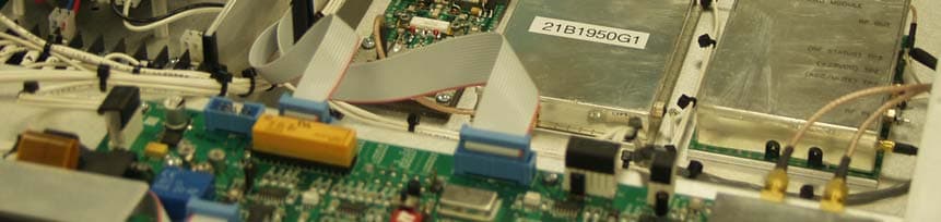
BZ5MXI030U
Mar 09, 2010Digital Television Broadcast Translator
Equipment Class
TBC - Licensed Broadcast Station Transmitter