BZ5DTT250MDigital Television Broadcast Translator
Larcan IncApplication Details
- Equipment Class
- TBC - Licensed Broadcast Station Transmitter
- Date of Grant
- Jul 22, 2010
- Application Purpose
- Original Equipment
- Date of Application
- Jul 04, 2010
- Equipment Note
- Digital Television Broadcast Translator
- Frequency Range
- 174.00000000 - 216.00000000
- Company
- Larcan Inc
- Country
- Canada
Documents & Files
Document Text
Text extracted from the exhibit documents filed with the FCC. Open a document above to read the original.
Users Manual
GENERAL DESCRIPTION TSM 20-275D rev 0: Jul 1, 2010 1 DTT250M DTT250M – 250W Digital Television Transmitter INTRODUCTION This manual describes the LARCAN model DTT250M VHF Digital Television Transmitter. LARCAN all‐solid‐state 250W VHF transmitters are designed to operate conservatively at 250W average DTV power with superb performance, reliability and operating economy. The transmitter and exciter or translator chassis are packaged in a single 19" cabinet. The simplicity of design, the deployment of all modular and other subassemblies, and the use of standard readily available components, enhances serviceability. Important transmitter parameters are monitored, and can be displayed on the meter built into the amplifier. Additionally, all meter readings are made available as DC signals for telemetry by remote control systems. The DTT250M, like all other LARCAN transmitting equipment, is suitable for automatic or remote‐control operation. AMPLIFIER CHAIN The RF output of the exciter is fed to a conservatively designed broadband solid‐state amplifier. This amplifier requires no tuning or adjustment within its band of operation. Simplicity of operation, reduced maintenance costs and increased reliability are a few of the major benefits derived from this modular amplifier. This module is operated well below its maximum ratings. The amplifier chain consists of three stages of amplification. The preamplifier stage is a high gain, broadband, thin‐film integrated circuit amplifier operating class A. The IPA stage consists of a pair of push‐pull FETs in a single case, operating in class AB as a linear amplifier. This amplifier uses the identical dual FET device that is used by the PA module. The final amplifier stage consists of six push‐pull FET amplifiers that operate in class AB, in three groups of two in quadrature, and are combined in quadrature and then in a 3‐way combiner. The amplifier module is rated for 250 watts average ATSC output. The module is provided with soft‐start, VSWR protection, and a monitor port. The amplifier output is fed to the bandpass filter and the directional coupler, which provides a small sample of forward and reflected output power for AGC and VSWR supervisory functions. The transmitter output then passes to the antenna system. GENERAL DESCRIPTION TSM 20-275D rev 0: Jul 1, 2010 2 DTT250M DTT250M – 250W Digital Television Transmitter TRANSMITTER CONTROL The control circuitry in this solid state transmitter is simple. Interlocking consists of the enabling circuitry necessary to ensure that any external patch panel link operation, or RF switching, can only be done with RF turned off. nable J5‐5. All control wiring of the transmitter passes through a control circuit board (prefix 5B), and facilities are provided on this board for telemetry, status, and control connections to and from a remote control system. These are available on 15 contact D‐shell connector J5. For local operation, simply place the LOC‐REM switch in the LOC position. For remote control operation the LOC‐REM switch must be in the REM position. This places +12V on Remote E The Remote Enable +12V appears as an arming signal at J5‐5, and the momentary connection of this +12V to J5‐13 turns the transmitter ON, and momentary connection of the +12V to J5‐8 turns the transmitter OFF. The transmitter control and interlock wiring is also brought out on J3, which is provided with a terminal block style of connector interface. Remote Enable, Remote On, Remote Off, and External Interlocks 1 and 2 are all brought out on J3 for connection as required. A thermostat is provided in the PA heatsink to open the interlock chain should an unlikely overheating condition occur. CONTENTS 1 BANDPASS FILTER ........................................................................................................................................................ 2 2 RF DIRECTIONAL COUPLER ...................................................................................................................................... 4 PUB96-26 Rev 1 September 13, 2005 26-1 RF Output: BP Filter & Directional Coupler 1 BANDPASS FILTER Drawing References: Figure 1 and Figure 4. The LARCAN bandpass filter implementation consists of a cascaded series of coupled helical resonators. A helical resonator is essentially a self supporting high Q coil (the helix) mounted inside a metallic shield enclosure. One end of the coil is solidly connected to the shield enclosure and the other end is open circuited except for a small trimmer capacitance to ground. The dimensions of the coil are critical as to frequency of operation; the assembly behaves as though it were a quarter wave coaxial transmission line resonator. Several sizes of coils and enclosures are necessary to cover the desired frequency ranges. Figure 4 indicates the generic assembly of a coupled helical resonator bandpass filter. The referenced drawing in Figure 4 is a low band filter, but the high band unit is laid out identically and appears almost the same, except the high band helixes have fewer turns of coarser winding pitch, and their shield enclosure dimensions are somewhat smaller. The desired response shape is presented as Figure 1, and the filter electrical equivalents are presented as Figure 2. When we examine the assembly, and take capacitances into account, the equivalent circuit of a helical resonator becomes simply a parallel resonant LC tank circuit having low (trimmer) capacitance and relatively high inductance. Adjustment of the trimmer produces a change of capacitance, and the trimmer's moveable slug is shaped to appear as a shorted turn, which alters the inductance of the helix. Matching from and to 50 ohm transmission lines is accomplished with taps on the input and output helixes. Coupling between sections is electrically a bridged T network of capacitors, and is made up of the small capacitance between the free ends of the coils, controllable by the amount of capacitance to g…
Text truncated - open the document above for the full version.
Attestation Statements
228 Ambassador Drive Mississauga ON Canada L5T 2J2 July 5, 2010 Office of Engineering and Technology Re: FCC ID BZ5DTT250M Reference code # 13EA186523 Dear Sir or Madame: I just recently submitted a Type Certification Application in which I realized after the fact that I made a mistake on the frequency tolerance specification. The specification (all three) should read 0.002% for frequency Tolerance and not 0.02%. As per the test report, we do indeed meet the tighter specification – it was simply a mistake on the data input that I made. Please change the application to reflect this. Sincerely, John Tremblay V. P. Engineering LARCAN U.S. Tel: 1-303-665-8000 Fax: 1-303-673-9900 Canada Tel: 1-905-564-9222 Fax: 1-905-564-9244 www.larcan.com Email: [email protected]
External Photos
BZ5DTT250M Application for FCC Certification 250 Watt Digital Television Translator Exterior Photo
ID Label/Location Info
BZ5DTT250M Application for FCC Certification 250 Watt Digital Television Translator FCC Label/Label Location
Internal Photos
BZ5DTT250M Application for FCC Certification 250 Watt Digital Television Translator Interior Photos of RF Amplifier
Operational Description
BZ5DTT250M Application for FCC Certification 250 Watt Digital Television Translator Operational Description: This application requests certification for a 250 Watt Digital Television Translator. The intended use of this digital translator is to rebroadcast a television relay station or other legal source of ATSC digital television signal. The DTT250 is a solid state digital regenerative translator designed to receive over-the- air ATSC signals, converting the RF signal to baseband digital format, processing the signal to eliminate noise, and then re-modulating, converting to the new broadcast channel, amplifying and filtering the signal before it is applied to the transmit antenna. The receive section of the translator and the output modulation format conform with FCC Part 73.682(d), ATSC Digital Television Standards. The DTT250 is self contained in a single cabinet. The Unit consists of power supply, amplifier, and driver and control and metering circuitry. The output mask filter is contained within the cabinet also. The cabinet of the DTT250 contains the 1RU RegenT Transcoder unit which receives processes and re-modulates the signal. The translator meets all FCC requirements for both the simple emissions mask and the stringent emissions mask. The output filter provides more than 85dB of attenuation within the GPS Frequency bands (1164-1240 MHz and 1559-1610 MHz). Note that since these products are frequency agile in that they can be field tuned for different channels within the VHF television band, each unit has this filtering included, regardless of the channel. Testing results shown in this document were conducted on channel 5 (79 MHz center frequency) with the exception of the frequency stability testing which was conducted on channel 7 (173 MHz). These test results are representative of performance on any channel in the VHF broadcast spectrum. Wiring, shielding and construction are in accordance with accepted principles of good engineering practice. The translator’s construction is such that all hazardous components are enclosed or protected against accidental contact by operating personnel.
Parts List/Tune Up Info
PARTS LIST: DTT250M Level Line Tp Component Description Rev ID Qty UM 1 1 1 10X0002G1 OPT FREQ AND POWER DTT250SV R3 1 EA 3 1 3 40D1137G1 PA 1KW MODULE 54-72MHZ BEIGE R37 1 EA 4 16 1 40D1206G1 PCB COMBINER ASSY R4 1 EA 5 14 5 PPR9752503100-5 RES 250W 5%100 R1 1 EA 5 15 5 PPR9752503100-5 RES 250W 5%100 R2 1 EA 5 16 5 PPR9752503100-5 RES 250W 5%100 R3 1 EA 5 17 5 3R152P510J RES 51R 1/4W 5% R4 1 EA 5 18 5 3R152P510J RES 51R 1/4W 5% R5 1 EA 5 19 5 3R152P510J RES 51R 1/4W 5% R6 1 EA 5 23 5 100B-150-JP500X CAP 15pF 500V 5% pellet C1 1 EA 5 24 5 100B-240-JP500X CAP 24pF 500V 5% pellet C2 1 EA 5 25 5 100B-240-JP500X CAP 24pF 500V 5% pellet C3 1 EA 5 26 5 100B-470-JP500X CAP 47pF 500V 5% pellet C4 1 EA 5 27 5 100B-470-JP500X CAP 47pF 500V 5% pellet C5 1 EA 5 28 5 630-09472 CAP 4.7nF 100V CERAMIC C6 1 EA 5 29 5 630-09472 CAP 4.7nF 100V CERAMIC C7 1 EA 5 30 5 100B-150-JP500X CAP 15pF 500V 5% pellet C8 1 EA 5 39 5 2-1/4-9-CW-20 INDUCTOR (20B1627) L1 1 EA 5 42 5 HP5082-2800 DIODE SEE IN5711 CR1 1 EA 5 43 5 HP5082-2800 DIODE SEE IN5711 CR2 1 EA 4 17 1 40D1209G1 PCB SPLITTER ASM R4 1 EA 5 14 5 PPR515203 100-5 RES 20W 5% 100 PPR5152031000J R1 1 EA 5 15 5 PPR515203 100-5 RES 20W 5% 100 PPR5152031000J R2 1 EA 5 16 5 PPR515203 100-5 RES 20W 5% 100 PPR5152031000J R3 1 EA 5 17 5 3R152P121J RES 120R 1/4W 5% R4 1 EA 5 23 5 100B-150-JP500X CAP 15pF 500V 5% pellet C1 1 EA 5 24 5 100B-150-JP500X CAP 15pF 500V 5% pellet C2 1 EA 5 25 5 100B-240-JP500X CAP 24pF 500V 5% pellet C3 1 EA 5 26 5 100B-240-JP500X CAP 24pF 500V 5% pellet C4 1 EA 5 27 5 100B-390-JP500X CAP 39pF 500V 5% pellet C5 1 EA 5 28 5 100B-390-JP500X CAP 39pF 500V 5% pellet C6 1 EA 5 29 5 630-09472 CAP 4.7nF 100V CERAMIC C7 1 EA 5 39 5 HP5082-2800 DIODE CR1 1 EA 5 42 5 2-1/4-9-CW-20 INDUCTOR (20B1627) L1 1 EA 4 18 1 30C1005G1 INPUT BD ASM R20 4 EA 5 20 5 MSC154K THERMISTOR RT1 1 EA 5 21 5 MSC154K THERMISTOR RT2 1 EA 5 23 5 100B-201-JP300X CAP 200pF 300V 5% pellet C1 1 EA Level Line Tp Component Description Rev ID Qty UM 5 24 5 100B-201-JP300X CAP 200pF 300V 5% pellet C2 1 EA 5 25 5 100B-620-JP500X CAP 62pF 500V 5% pellet C3 1 EA 5 26 5 100B-201-JP300X CAP 200pF 300V 5% pellet C4 1 EA 5 33 5 3R152P203J RES 20k 1/4W 5% R1 1 EA 5 34 5 3299P-1-104 POT 100K R2 1 EA 5 35 5 SFR25H5R1J RES, 1/2W 5% 5R1 R1 R3 1 EA 5 36 5 3R152P332J RES 3.3k 1/4W 5% R4 1 EA 5 37 5 3R152P332J RES 3.3k 1/4W 5% R5 1 EA 5 38 5 SFR25H5R1J RES, 1/2W 5% 5R1 R1 R6 1 EA 5 39 5 3299P-1-104 POT 100K R7 1 EA 5 40 5 3R152P203J RES 20k 1/4W 5% R8 1 EA 5 42 5 RG178B/U CBL RF FLEX 50R OD 0.080" T1 1 IN 5 43 5 5051-3104K CAP u1 250V FILM C6 1 EA 5 44 5 5051-3104K CAP u1 250V FILM C7 1 EA 4 19 1 30C1006G1 PCB ASSY OUTPUT R12 4 EA 5 23 5 100B-102-JP50X CAP 1nF 50V 5% pellet C9 1 EA 5 24 5 2222-119-28479 CAP 47u 63V ELECT PREFERRED C10 1 EA 5 25 5 100B-102-JP50X CAP 1nF 50V 5% pellet C11 1 EA 5 26 5 2222-119-28479 CAP 47u 63V ELECT PREFERRED C12 1 EA 5 27 5 100B-820-JP500X CAP 82pF 500V 5% pellet C13 1 EA 5 28 5 100B-910-JP500X CAP 91pF 500V 5% pellet C14A/B 2 EA 5 29 5 100B-910-JP500X CAP 91pF 500V 5% pellet C15A/B 2 EA 5 30 5 100B-510-JP500X CAP 51pF 500V 5% pellet C16 1 EA 5 31 5 5051-3334K CAP u33 250V FILM C5 1 EA 5 32 5 5051-3334K CAP u33 250V FILM C8 1 EA 5 38 5 10A571P13 CHOKE 3T 1/4" I.D #20 L4 1 EA 5 39 5 10A571P13 CHOKE 3T 1/4" I.D #20 L5 1 EA 5 43 5 UT-85C TP 50 ^ COAX CABLE 50 OHM TIN PLATED 0 FT 4 34 5 AGC7 FUSE 7A 32V 8 EA 4 35 5 SRF3943-2 TRANSISTOR 4 EA 4 37 5 20B1594G1-Z PCB ASM VSWR CONTROL R-10 R-10 1 EA 4 43 1 10A1296G1 PCB ASM & RF CONNECTOR R-6 R-6 1 EA 4 45 3 10A1270G1 D.C. CONNECTOR ASM MALE R8 1 EA 4 62 5 366-55103 CAP 10n 400V FILM C20 4 EA 4 63 5 366-55103 CAP 10n 400V FILM C21 4 EA 4 66 5 100B-102-JP50X CAP 1nF 50V 5% pellet C17 1 EA 3 8 1 20B534G10 DIR CPLR ASSY QUAD R22 1 EA 4 19 1 10A1942G1 QUAD DIR CPLR PCB ASSY R-3 R-3 1 EA 5 11 5 PR37J 51 OHMS RES 1.6W 5% 51 R1 1 EA 5 12 5 PR37J 51 OHMS RES 1.6W 5% 51 R2 1 EA 5 13 5 9C12063A51R0JL RES 51R 1/4W 5% 1206 R3 1 EA Level Line Tp Component Description Rev ID Qty UM 5 14 5 9C12063A51R0JL RES 51R 1/4W 5% 1206 R4 1 EA 5 17 5 10A584P2 COIL -#16 GA R-2 R-2 L1 1 EA 5 18 5 10A584P2 COIL -#16 GA R-2 R-2 L2 1 EA 5 19 5 10A584P2 COIL -#16 GA R-2 R-2 L3 1 EA 5 20 5 10A584P2 COIL -#16 GA R-2 R-2 L4 1 EA 5 24 5 681-09398 CAP 3p9 100V CERAMIC C1 1 EA 5 25 5 681-09398 CAP 3p9 100V CERAMIC C2 1 EA 5 26 5 681-09478 CAP 4p7 100V CERAMIC C3 1 EA 5 27 5 681-09478 CAP 4p7 100V CERAMIC C4 1 EA 3 11 1 30C1892G2 IPA MODULE ASSY CH2-4 R12 1 EA 4 17 5 MC48B3 FAN 1 EA 4 22 1 10A1453G2 PHASE SHIFTER LB 18dB R24 1 EA 5 13 5 MHW6185 HYBRID U2 1 EA 5 19 5 681-10121 CAP 120p 100V CERAMIC C1 1 EA 5 20 5 681-10121 CAP 120p 100V CERAMIC C2 1 EA 5 21 5 681-09478 CAP 4p7 100V CERAMIC C4 1 EA 5 22 5 681-09478 CAP 4p7 100V CERAMIC C5 1 EA 5 23 5 030-38108 CAP 1uF 63V ELECT C6 1 EA 5 24 5 030-38108 CAP 1uF 63V ELECT C7 1 EA 5 25 5 030-38109 CAP 10uF 63V ELECT C3 1 EA 5 26 5 630-09472 CAP 4.7nF 100V CERAMIC C8 1 EA 5 27 5 630-09472 CAP 4.7nF 100V CERAMIC C9 1 EA 5 30 5 BB809 DIODE VARACTOR CR1 1 EA 5 31 5 BB809 DIODE VARACTOR CR2 1 EA 5 32 5 BB809 DIODE VARACTOR CR3 1 EA 5 33 5 BB809 DIODE VARACTOR CR4 1 EA 5 34 5 10A212P1 COIL 7t R-6 R-6 L1 1 EA 5 35 5 10A212P1 COIL 7t R-6 R-6 L2 1 EA 5 36 5 10A212P1 COIL 7t R-6 R-6 L3 1 EA 5 38 5 3R152P102J RES 1k 1/4W 5% R1 1 EA 5 39 5 3006P-1-103 POT 10K R2 1 EA 5 42 5 M2001HP2-50R-20dB ATTENUATOR(SUB MAP-1000 KDI) R5 1 EA 5 44 5 PSCQ-2-90 HYBRID LOW BAND U1 1 EA 5 46 5 MC7824CT IC VOLT REG TTC # 8220-017 U3 1 EA 5 49 5 06/01/2001 SPECTROL COVER 1 EA 4 28 5 SRF3943-2 TRANSISTOR 1 EA 4 29 5 AGC7 FUSE 7A 32V 2 EA 4 30 1 30C1054G1 PCB ASM INPUT R14 1 EA 5 8 5 630-09102 CAP 1nF 100V CERAMIC C23 1 EA 5 9 5 630-09102 CAP 1nF 100V CERAMIC C24 1 EA 5 15 5 MSC154K THERMISTOR RT1 1 EA Level Line Tp Component Description Rev ID Qty UM 5 16 5 MSC154K THERMISTOR RT2 1 EA 5 19 5 1N5357A ZENER DIODE SAME AS IN5357B CR1 1 EA 5 20 5 1N5357A ZENER DIODE SAME AS IN5357B CR2 1 EA 5 21 5 2062-0000-00 RECEPTACLE SEE 50-651-0000-31 J1 1 EA 5 23 5…
Text truncated - open the document above for the full version.
Parts List/Tune Up Info
BZ5DTT250M Application for FCC Certification 250 Watt Digital Television Translator Parts List and Tune-up Procedure/Active Devices: The following is the procedure for changing the channel of the DTT250M translator. Since the amplifier is broadband, channel change involves retuning of the output filter and recalibration of the output meter. The amplifier meter was calibrated to read 100% (top scale) at full power and at the channel specified when the transmitter was tested at the factory. If the amplifier is to operate at a channel other than that of the factory test channel, the metering will require re-calibration. The power meter setting is a channel dependent calibration. 1. Connect the transmitter output to a 50 ohm dummy load or the antenna. The transmitter uses a 50Ω type N connector for its output. Calibrated directional coupler and suitable digital wattmeter should be used for measurements. 2. Connect the AC mains input. This AC circuit should be rated for 30 amperes, and should be supplied through a slow-tripping breaker or time delay fuse. Generally, a breaker that is rated for across-the-line motor starting will be found to be satisfactory. Connect the power supply to the amplifier. 3. At this point the LCD display should be illuminated, and the transmitter should be OFF. Depress the ON’ switch. The green LEDs should illuminate and the amplifier should be operating. The cooling fans on both the power supply and the amplifier should be running. 4. Attach the RF output power measuring device. 5. Turn down the drive level from the Transcoder (front end) before applying any RF input signal. 6. Slowly turn up the drive level until the output power reaches the desired level (on the power measuring device – not the transmitter power meter indication). 7. When the output power is at the desired level check that the voltage at U4-7 (Metering PC board) is 3.0VDC (Adjust with R29). At this point the transmitter forward power meter should read 100%. 8. To calibrate the reflected power, remove the cable from J1 at the metering board and reconnect through a 16dB attenuator to J2. 9. Adjust potentiometer R30 for a reflected power meter reading of 25% (reading multiplication factor is 10x – ie: corresponds to 2.5% reflected). Voltage at U4-1 shouldread 1.5VDC. 10. Adjust R36 to cause reflected power to drop to a meter reading of 20%. Adjust R42 until VSWR cutback LED illuminates. 11. Replace 16dB attenuator with 10dB attenuator, and adjust R49 until transmitter locks out. 12. Reconnect the cables as they were. The output filter must be re-tuned as per the frequency response sweeps: BZ5DTT250M Application for FCC Certification 250 Watt Digital Television Translator Parts List and Tune-up Procedure Mask Filter: Bandpass Response BZ5DTT250M Application for FCC Certification 250 Watt Digital Television Translator Parts List and Tune-up Procedure Mask Filter: Return loss
Schematics
TRANSMITTER RF OUTPUT BANDPASS FILTER AND DIRECTIONAL COUPLER PUB96-26 Rev 1 September 13, 2005 26-1 RF Ou tput: BP Filter & Directional Coupler Figure 4 Generic Bandpass Filter Assembly 30C1064 sht2 Rev 3 TRANSMITTER RF OUTPUT BANDPASS FILTER AND DIRECTIONAL COUPLER PUB96-26 Rev 1 September 13, 2005 26-2 RF Ou tput: BP Filter & Directional Coupler Figure 5 RF Directional Coupler Assembly 20B534 sht4 Rev 6 PUB96-32 Rev 2 August 29, 2005 TX Control Panel 40D1985G1 LOW POWER VHF TRANSMITTER CONTROL PANEL Figure 2 Transmitter Control Board Schematic 30C1829 sht7 POWER AMPLIFIER 1.5KW HIGH BAND 40D1493G3 PUB96 ‐ 29 Rev 2 12 24 Oct 2008 Figure 3 Module Schematic 30C1302 sht1 rev 1 POWER AMPLIFIER 1.5KW HIGH BAND 40D1493G3 PUB96 ‐ 29 Rev 2 14 24 Oct 2008 Figure 5 Single Stage PA Schematic 30C1305 sht 1 rev 8 POWER AMPLIFIER 1.5KW HIGH BAND 40D1493G3 PUB96 ‐ 29 Rev 2 17 24 Oct 2008 Figure 8 Module VSWR Protection Board Schematic 30C1418 sht 1 rev 6 POWER AMPLIFIER LOW BAND PUB96 ‐ 28 Rev 2 8 24 Oct 2008 Figure 3 Module Schematic 30C1307 rev 2 POWER AMPLIFIER LOW BAND PUB96 ‐ 28 Rev 2 10 24 Oct 2008 Figure 5 Single Stage PA Schematic 30C1306 sht 1 rev 8
Test Report
BZ5DTT250M Application for FCC Certification 250 Watt Digital Television Translator Spurious Emissions
Test Report
BZ5DTT250M Application for FCC Certification 250 Watt Digital Television Translator Cabinet Radiation BZ5DTT250M Application for FCC Certification 250 Watt Digital Television Translator Cabinet Radiation
Test Report
BZ5DTT250M Application for FCC Certification 250 Watt Digital Television Translator Frequency Drift versus Temperature READINGS CALCULATION LOCAL OSC'R FREQ (MHZ) DEVIATION FROM REF TEMP (DEG C) VAC= 102 120 138 (Hz) (%) 20 (REF) 174312212174312212174312212ref -30 1743092501743092501743092502962 0.001699 -20 1743102001743102001743102002012 0.001154 -10 1743110751743110751743110751137 0.000652 0 174311575174311575174311575637 0.000365 10 174312075174312075174312075137 0.000079 20 1743122121743122121743122120 0.000000 30 17431213517431213517431213577 0.000044 40 174312100174312100174312100112 0.000064 50 17431227517431227517431227563 0.000036 60 174312550174312550174312550338 0.000194 Test Setup for Frequency Stability measurements. Test Equipment List: Thermostatically controlled Temperature Chamber – Cincinnati Sub-Zero HP 8594E Spectrum Analyzer S/N: 3303A00399
Test Report
BZ5DTT250M Application for FCC Certification 250 Watt Digital Television Translator Power Measurements The translator’s power meter circuit uses a detected sample from a coupler on the output. An averaging detector circuit provides the DC level to drive the translator’s output level meter. The translator was connected to a test load through a calibrated directional coupler. The spectrum analyzer’s “Channel Power” function was used to measure the average power level of the signal as sampled through the directional coupler. (see Fig.) . Measured power: 10.1 dBm Coupling loss: -43.9 dB Attenuator @ i/p to spectrum analyzer 0 dB Power: 54 dBm Power = 250 Watts
Test Report
BZ5DTT250M Application for FCC Certification 250 Watt Digital Television Translator Attenuation Characteristics
Test Report
BZ5DTT250M Application for FCC Certification 250 Watt Digital Television Translator Digital Signal: Eye Diagram/Signal to Noise Ratio/Error Vector Magnitude
Test Setup Photos
BZ5DTT250M Application for FCC Certification 250 Watt Digital Television Translator Test Setup Photo: Block Diagram of Test Setup: Test Equipment: Instrument Make/Model Serial # Last Cal. Date. Spectrum Analyzer HP8594E 3303A00399 Dec. 3, 2003 Signal Analyzer Agilent 89441 VSB Analyzer US39314237 Mar. 31 2010 RF Network Analyzer Agilent 8712ET US40371604 Mar. 6, 2000
Contact Information
Applicant
John E. Tremblay(Engineering, Vice President)
Technical Contact
LARCAN Inc.John Tremblay
[email protected]905 564 9222
228Ambassador Drive · Mississauga, Ontario · Canada
Non-Technical Contact
LARCAN Inc.John Tremblay
[email protected]905 564 9222
Technical Specifications
| # | Rule Parts | Frequency Range | Power Output | Emission | Tolerance |
|---|---|---|---|---|---|
| 3 | 74 | 174 MHz - 216 MHz | 250 W | 6M00K1D | 0.002 % |
Other Applications from Larcan Inc
BZ5DTR10SC
Jun 16, 2014Digital Television Translator
Equipment Class
TBC - Licensed Broadcast Station Transmitter
BZ5MXI1503U
Aug 04, 2013Television Broadcast Translator
Equipment Class
TBC - Licensed Broadcast Station Transmitter
BZ5MXI1002U
Jul 11, 2012Digital Television Translator
Equipment Class
TBC - Licensed Broadcast Station Transmitter
BZ5MXI501U
Nov 22, 2010Digital Television Broadcast Translator
Equipment Class
TBC - Licensed Broadcast Station Transmitter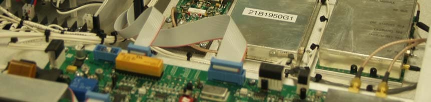
BZ5MXI030U
Mar 09, 2010Digital Television Broadcast Translator
Equipment Class
TBC - Licensed Broadcast Station Transmitter