BZB2000XTWIRELESS MICROPHONE
Azden Corporation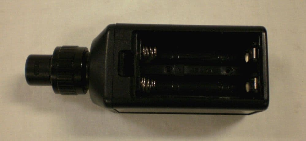
Click to zoom
Application Details
- Equipment Class
- TNF - Licensed Non-Broadcast Transmitter Held to Face
- Date of Grant
- Aug 21, 2012
- Application Purpose
- Original Equipment
- Date of Application
- Aug 21, 2012
- Equipment Note
- WIRELESS MICROPHONE
- Frequency Range
- 638.10000000 - 661.89000000
- Company
- Azden Corporation
- Country
- Japan
Documents & Files
Document Text
Text extracted from the exhibit documents filed with the FCC. Open a document above to read the original.
Users Manual
4.Operating Menu 42 -01␣ Press mode key for 1s 638.125 5s later Channel Select Frequency Up or Down 42-15␣ Change the CH 1.4s laterUp or DownMode key Group Select a hyphen flashing Change the Group a hyphen glows 02:15␣␣ Estimated Time [Channel Select mode] Select the channel by Up or Down key. (The frequency will be displayed by pressing a mode key for 1s) [Group Select mode] 1.Select the group by Up or Down key when a hyphen flashing. 2.The selected group will be enabled by pressing a mode key.(a hyphen glows) [Use Time] Displays the accumulated battery use time as a rough estimate of total transmitter usage. ␣Gr␣␣␣␣Gr -0␣␣Gr -1␣␣Gr -1␣ Mode key
Cover Letter(s)
N^rRFhl" AZDEN CORPORATION 147 NEW HYDE PARK ROAD, FRANKLIN SQUARE, NY 11010 PHONE: 515-328-7500 FAX: 515-328-7505 EMAIL: [email protected] WEBSITE: www.azdencorp.com Federal Communications Commission Authorization and Evaluation Division Confidentiality Request regarding application for certification of FCC LD:BZB2000XT. Pursuant to Sections 0.457 and 0.459 of the Commission's Rules, we hereby request confidential treatment of information accompanying this application as outlined below: Exhibit Type File Name Schematics 6.Schem-AF&CONT.pdf T.Schem-RF&POW.pdf Block Diagram S.Block Diagram.pdf Circuit Description 2.Voltage and current at RF part.pdf The above materials contain trade secrets and proprietary information not customarily released to the public. The public disclosure of these materials may be harmful to the applicant and provide unjustified benefits to its competitors. Sincerely, O Sho Torii, Director Azden Corporation
External Photos
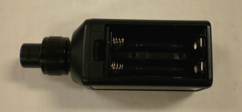
APPLICANT: AZDEN CORPORATION FCC ID: BZB2000XT EXTERNAL PHOTOS
Internal Photos
APPLICANT: AZDEN CORPORATION FCC ID: BZB2000XT INTERNAL PHOTOS
Parts List/Tune Up Info
1.Adjustment Manual IssueY M D Azden Adjustment Standard Category Y M D33-543-01 (2000XT) Adjustment ManualNo. Power supply:3.0V Channel and Frequency List used on the adjustment ChannelFrequency 42-01638.125MHz 43-47649.875MHz 45-47661.875MHz 1.Adjustment of VCO 1) Set the channel to 42-01 2) Connect the DC voltmeter to TP201 3) Confirm the DC voltmeter indicates 1.3V 4) Set the channel to 45-47 and confirm the voltage is 2.1V on the DC voltmeter 2.Adjustment of the RF output power 1) Set the channel to CH43-47 2) Connect the power meter to CN201 3) Adjust the power to 50mW by VR201 4) Connect the spectrum analyzer to CN201 5) Confirm that the difference of the RF Level between carrier and spurious is at least 40dB. 3.Adjustment of the transmitting frequency 1) Set the frequency to CH43-47 2) Connect the frequency counter to CN201 3) Adjust VC201 so that the frequency counter shows 649.875MHz 4.Confirm the tone frequency and adjustment of the deviation level. 1)Connect the frequency counter to TP101 and confirm the frequency is 32.768kHz. 2)Connect TP102 and GND. 3)Connect the linear detector to CN201. 4)Adjust VR3 so that the deviation level is plus-minus 3.0kHz. 5.Adjustment of the AF modulation 1)Set SW201:OFF SW2:ON 2) Connect the RC Oscillator to TP11(HOT).SHORT TP10(COLD) and GND. 3) Set the oscillator output level -35dBu(The frequency is 1kHz) 4) Connect the AC voltmeter to TP101. 5) Adjust the VR100 so that the voltmeter shows -17dBu. 6) Connect the linear detector to CN201. 7) Adjust VR202 so that the deviation level of AF&TONE is plus-minus 23kHz 8)Connect TP102 and GND.Readjust the deviation level of TONE is plus-minus 3.0kHz. 9)Set the oscillator output level to -60dBu(The frequency is 1kHz) 10)Adjust VR2 so that the first AF Level indicator appears. Adjusted date 6.Confirming of the battery indicator 1) Supply 2.5V to the transmitter and cofirm that the battery status indicates 3 levels . 2) Supply 2.0V to the transmitter and cofirm that the first indicator is flashing. 7.Other confirming points 1) Set up the receiver for communication check 2) Connect the lavalier microphone to the transmitter and send the audio to check whether it operates correctly 3) Make an impact on the body and check whether the unit does not show any abnormal sound 5) Factory default conditions [Power]:OFF, [Channel]:42-01,[Audio SW]:OFF,[Phantom Power]:OFF Azden corp. 2.Voltage and current at RF part 1.Voltage and current at RF part Low(CH42-01)Mid(CH43-47)High(CH45-47) Vce3.5V3.5V3.4 Ic25mA26mA28mA 2.Description of main feature of circuit (1)Stabilization of frequency Oscillation method :PLL synthesized The stabilization of this oscillation method relies on crystal oscillator performance. Its accecting range is frequency deviation plus-minus 10ppm or less,under -10 degree to +60 degree temperature by using Tokyo Denpa made crystal oscillator. (2)How to reduce the spurious radiation In order to suppress the radiation,LC filter is positioned after current amplification part. It is low passed filter which forms pie shape with third layered. (3)Restriction of Audio modulation In order to restrict audio modulation,diode limiter circuit(ZD101,ZD102) is put into pre-emphasis circuit.
Test Report
FCC PART 74 AND INDUSTRY CANADA RSS-123 LOW POWER LICENSED TRANSMITTER TEST REPORT APPLICANT AZDEN CORPORATION 1-12-17 KAMI-RENJAKU MITAKA, TOKYO 181 JAPAN FCC ID BZB2000XT IC CERT 2817B-2000XT MODEL NUMBER 2000XT PRODUCT DESCRIPTION WIRELESS MICROPHONE DATE SAMPLE RECEIVED 4/27/2012 DATE TESTED 5/30/2012 TESTED BY Joe Scoglio APPROVED BY Mario R. de Aranzeta TIMCO REPORT NO. 1098AUT12TestReport.doc TEST RESULTS PASS FAIL THE ATTACHED REPORT SHALL NOT BE REPRODUCED EXCEPT IN FULL WITHOUT THE WRITTEN APPROVAL OF TIMCO ENGINEERING, INC. 849 NW STATE ROAD 45 NEWBERRY, FL 32669 USA PH: 888.472.2424 OR 352.472.5500 FAX: 352.472.2030 EMAIL: [email protected] HTTP://WWW.TIMCOENGR.COM Certificate # 0955-01 Applicant: AZDEN CORPORATION FCC ID: BZB2000XT IC #: 2817B-2000XT MODEL #: 2000XT REPORT: A\AZDEN_BZB\1098AUT12\1098AUT12TestReport.doc Page 2 of 17 TABLE OF CONTENTS GENERAL REMARKS ........................................................................................................... 3 GENERAL INFORMATION .................................................................................................... 4 TEST PROCEDURES ............................................................................................................ 6 RF POWER OUTPUT ............................................................................................................ 7 MODULATION CHARACTERISTICS ...................................................................................... 8 VOICE MODULATED COMMUNICATION EQUIPMENT......................................................... 9 AUDIO INPUT VERSUS MODULATION ............................................................................... 10 OCCUPIED BANDWIDTH ................................................................................................... 11 SPURIOUS EMISSIONS AT ANTENNA TERMINALS (CONDUCTED) .................................... 13 FIELD STRENGTH OF SPURIOUS EMISSIONS .................................................................. 14 FREQUENCY STABILITY .................................................................................................... 16 EMC EQUIPMENT LIST ...................................................................................................... 17 Applicant: AZDEN CORPORATION FCC ID: BZB2000XT IC #: 2817B-2000XT MODEL #: 2000XT REPORT: A\AZDEN_BZB\1098AUT12\1098AUT12TestReport.doc Page 3 of 17 GENERAL REMARKS The attached report shall not be reproduced except in full without the written permission of Timco Engineering Inc. The test results relate only to the items tested. Summary The device under test does: fulfill the general approval requirements as identified in this test report not fulfill the general approval requirements as identified in this test report Attestations This equipment has been tested in accordance with the standards identified in this test report. To the best of my knowledge and belief, these tests were performed using the measurement procedures described in this report. All instrumentation and accessories used to test products for compliance to the indicated standards are calibrated regularly in accordance with ISO 17025: 2005 requirements. Certificate # 0955-01 I attest that the necessary measurements were made, under my supervision, at: Timco Engineering Inc. 849 NW State Road 45 Newberry, Fl 32669 Authorized Signatory Name: Mario de Aranzeta C.E.T. Compliance Engineer/ Lab. Supervisor Date: May/30/2012 Applicant: AZDEN CORPORATION FCC ID: BZB2000XT IC #: 2817B-2000XT MODEL #: 2000XT REPORT: A\AZDEN_BZB\1098AUT12\1098AUT12TestReport.doc Page 4 of 17 GENERAL INFORMATION RULES PART 2.1033 DUT TECHNICAL DESCRIPTION DUT Description WIRELESS MICROPHONE FCC ID BZB2000XT IC Certification 2817B-2000XT Model Number 2000XT Modulation FM Type of Emission 130KOF3E Bn = 2M+2DK M = 15000 D = 50 kHz (Peak Deviation) K = 1 Bn = 2(15k) + 2(50k)(1) = 130k Frequency Range 638.10-661.89 Test Frequencies 638.10, 650.10, 661.89 MHz Maximum Output Power 0.010 W DUT Power Source 110–120Vac/50– 60Hz DC Power Battery Operated Exclusively Test Item Prototype Pre-Production Production Type of Equipment Fixed Mobile Portable Applicant: AZDEN CORPORATION FCC ID: BZB2000XT IC #: 2817B-2000XT MODEL #: 2000XT REPORT: A\AZDEN_BZB\1098AUT12\1098AUT12TestReport.doc Page 5 of 17 GENERAL INFORMATION Test Facility Timco Engineering, Inc. 849 NW State Road 45, Newberry, FL 32669 Test Condition The temperature was 26ºC with a relative humidity of 50%. Modifications None Test Exercise (e.g software description, test signal, etc.) The DUT was placed in continuous transmit mode of operation. Applicable Standards ANSI/TIA 603-C: 2004, FCC CFR 47 Parts 2 and 74, RSS- 123 Issue 1, Rev. 2 Applicant: AZDEN CORPORATION FCC ID: BZB2000XT IC #: 2817B-2000XT MODEL #: 2000XT REPORT: A\AZDEN_BZB\1098AUT12\1098AUT12TestReport.doc Page 6 of 17 TEST PROCEDURES Power Line Conducted Interference: The procedure used was ANSI/TIA 603-C: 2004 using a 50uH LISN. Both lines were observed with the DUT transmitting. The bandwidth of the spectrum analyzer was 10 kHz with an appropriate sweep speed. Bandwidth 20 dB: The measurements were made with the spectrum analyzer's resolution bandwidth (RBW) = 1 MHz and the video bandwidth (VBW) = 3 MHz and the span set as shown on plot. Power Output: For a device with a fixed antenna, RF power is measured as ERP as the antenna is permanently attached. The substitution method was used as described in ANSI/TIA-603-C: 2004. Antenna Conducted Emissions: The RBW = 100 kHz, VBW = 300 kHz and the span set to 10.0 MHz and the spectrum was scanned from 30 MHz to the 10 th Harmonic of the fundamental. Above 1 GHz the resolution bandwidth was 1 MHz , the VBW = 3 MHz, and the span 50 MHz. Radiation Interference: The test procedure used was ANSI/TIA 603-C: 2004 using an Agilent spectrum receiver with preselector. The bandwidth (RBW) of the spectrum receiver was 100 kHz up to 1 GHz and 1 MHz above 1 GHz with an appro…
Text truncated - open the document above for the full version.
Contact Information
Applicant
Toyohiko Tokitomo(Manager, QC Division)
Test Firm
Timco Engineering, Inc.Bruno Clavier
Technical Specifications
| # | Rule Parts | Frequency Range | Power Output | Emission | Tolerance |
|---|---|---|---|---|---|
| 1 | 74 | 638.1 MHz - 661.89 MHz | 10.00 mW | 11K0F3E | 2.7100000000 ppm |
Other Applications from Azden Corporation
BZB2000BT
Jan 03, 2012UHF WIRELESS MICROPHONE
Equipment Class
TBC - Licensed Broadcast Station Transmitter
BZB30BTL
Apr 17, 2007WIRELESS MICROPHONE TRANSMITTER
Equipment Class
TBT - Licensed Broadcast Transmitter Worn on Body
BZB30XT
Apr 04, 2007HANDHELD WIRELESS MICROPHONE
Equipment Class
TBF - Licensed Broadcast Transmitter Held to Face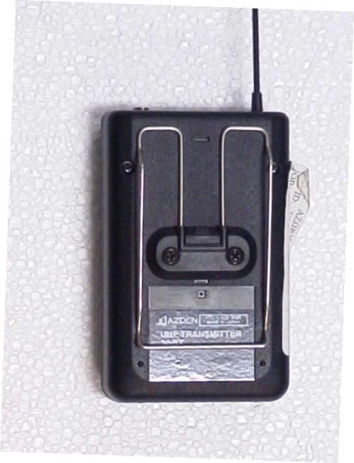
BZB30BT
Oct 31, 2006BELTPACK WIRELESS MICROPHONE
Equipment Class
TBT - Licensed Broadcast Transmitter Worn on Body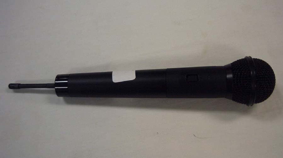
BZB51HT
Aug 04, 2004HANDHELD WIRELESS MICROPHONE
Equipment Class
TBF - Licensed Broadcast Transmitter Held to Face