BZB30XTHANDHELD WIRELESS MICROPHONE
Azden Corporation
Click to zoom
Application Details
- Equipment Class
- TBF - Licensed Broadcast Transmitter Held to Face
- Date of Grant
- Apr 04, 2007
- Application Purpose
- Original Equipment
- Date of Application
- Apr 04, 2007
- Equipment Note
- HANDHELD WIRELESS MICROPHONE
- Frequency Range
- 794.00000000 - 806.00000000
- Company
- Azden Corporation
- Country
- Japan
Documents & Files
Document Text
Text extracted from the exhibit documents filed with the FCC. Open a document above to read the original.
Users Manual
147 New Hyde Park Road ~ PO Box 10 ~ Franklin Square, NY 11010 Phone 516-328-7500 ~ Fax 516-328-7506 ~ Website: www.azdencorp.com ~ E-mail: [email protected] 30XT Transmitter Instructions (1) Open the battery compartment lid by sliding it down and lifting it up. (2) Insert one 9 volt battery into the compartment. Make sure the battery polarity is correct as marked inside the battery compartment. (3) Power Switches the transmitter “On” or “Off”. (4) Audio Prior to first turning the 30XT ON it is best to set the AUDIO switch to OFF. When you are ready to begin transmitting, switch to ON. The OFF position acts as a “mute” that maintains the RF signal but turns off the audio. (5) Mic Connector/Locking Ring This 3-pin XLR connector is the microphone input. Any low impedance microphone with a corresponding connector can be attached here. Once the microphone is plugged into the 30XT the locking ring should be rotated clockwise until snug. To remove the microphone, first rotate the locking ring counterclockwise and then, while pressing the XLR release, pull the microphone away from the 30XT. (6) Mic Input Level Control The mic input level control enables you to adjust the input level of the connected microphone. Using the supplied tool, turn the dial clockwise to increase, or counterclockwise to decrease the input level. (7) LCD Display: The display will light up when the power is turned “On”. The LCD displays show the following information. Channels numbered 1 to 240. Battery Condition: Using a 3 step indicator. (1 Low to 3 High) To change the channel number, use the tip of the tool provided and press the UP or Down button to the desired channel, numbered from 1 to 240. Once the desired channel number has been selected on the transmitter, set the receiver to the same channel number.
External Photos
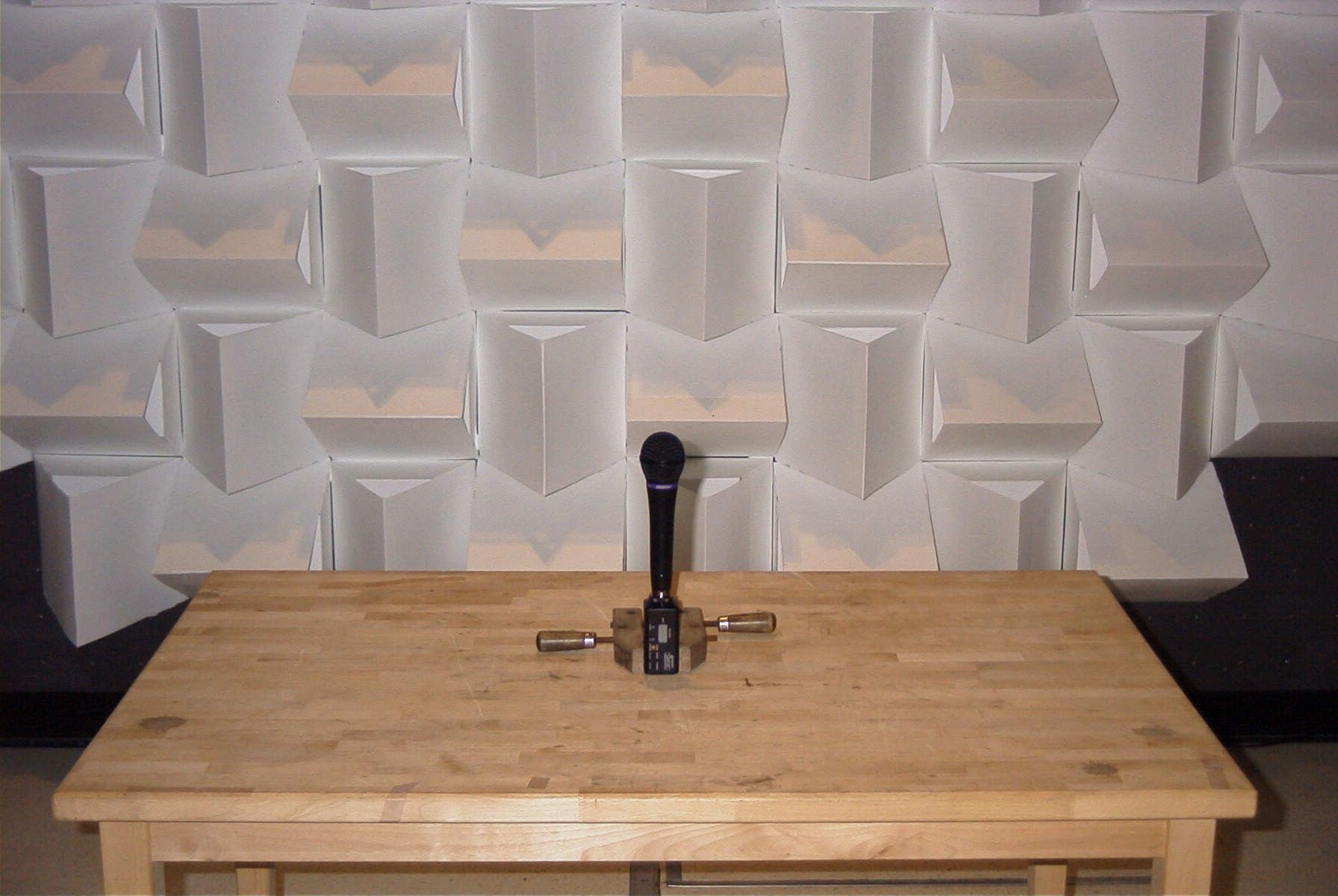
AZDEN CORP. FCC ID: BZB30XT EXTERNAL PHOTOS
Internal Photos
AZDEN CORP. FCC ID: BZB30XT INTERNAL PHOTOS
Test Report
849 NW STATE ROAD 45 NEWBERRY, FL 32669 USA PH: 888.472.2424 OR 352.472.5500 FAX: 352.472.2030 Email: [email protected] Email: [email protected] HTTP://WWW.TIMCOENGR.COM FCC Part 74 And Industry Canada RSS-123 Test Report APPLICANT AZDEN CORPORATION ADDRESS 1-12-17 KAMI-RENJAKU MITAKA, TOKYO 181 JAPAN FCC ID BZB30XT MODEL NUMBER 30XT PRODUCT DESCRIPTION Wireless Microphone DATE SAMPLE RECEIVED February 5, 2007 DATE TESTED February 5, 2007 TESTED BY Mario de Aranzeta APPROVED BY Frank DeNuzzo TIMCO REPORT NO. 3113UT6TestReport.doc TEST RESULTS PASS FAIL THE ATTACHED REPORT SHALL NOT BE REPRODUCED EXCEPT IN FULL WITHOUT THE WRITTEN APPROVAL OF TIMCO ENGINEERING, INC. Certificate #0955-01 APPLICANT: AZDEN CORPORATION FCCID: BZB30XT REPORT #: A\AZDEN\3113UT6\3113UT6TestReport.doc TITLE PAGE APPLICANT: AZDEN CORPORATION FCCID: BZB30XT REPORT #: A\AZDEN\3113UT6\3113UT6TestReport.doc TABLE OF CONTENTS AZDEN CORPORATION FCC ID: BZB30XT TABLE OF CONTENTS LIST GENERAL INFORMATION REQUIRED FOR CERTIFICATION................................................ 2 RF POWER OUTPUT 2.1046........................................................................................................... 3 MODULATION CHARACTERISTICS 2.1047(a)(b):...................................................................... 4 OCCUPIED BANDWIDTH:.............................................................................................................. 6 SPURIOUS EMISSIONS AT ANTENNA TERMINALS (conducted) 2.1051: ............................... 8 FIELD STRENGTH OF SPURIOUS EMISSIONS 2.1053(a)(b): ................................................... 9 FREQUENCY STABILITY 2.1055:............................................................................................... 12 EMC EQUIPMENT LIST ................................................................................................................ 13 APPLICANT: AZDEN CORPORATION FCCID: BZB30XT REPORT #: A\AZDEN\3113UT6\3113UT6TestReport.doc Page 2 of 13 GENERAL INFORMATION REQUIRED FOR CERTIFICATION 2.1033(c)(1) AZDEN CORPORATION will manufacture the BZB30XT in quantity, for use under FCC RULES 2.1033(c)(2) RULES PART 74.801, LOW POWER AUXILIARY STATIONS. AZDEN CORPORATION 1-12-17 KAMI-RENJAKU MITAKA, TOKYO 181 JAPAN 2.1033 TECHNICAL DESCRIPTION (c)(4) Type of Emission: 76K0F3E Bn = 2M + 2DK M = 10000 D = 28kHz(Peak Deviation) K = 1 Bn = 2(10k) + 2(28k)(1) = 76k ALLOWED AUTHORIZED BANDWIDTH = 200kHz. 74.861(e)(5) (c)(5) Frequency Range: Part 74: 723.00 - 735.00 MHz TEST FREQ = 723.00 MHz, 728.96MHz, and 735.00 MHz 794.00 – 806.00 MHz TEST FREQ = 794.00 MHz, 800.00MHz, and 805.95MHz (c)(6) Power Range and Controls:EUT has no controls. (c)(7) Maximum Output Power Rating: 0.01 Watts ERP (c)(8) DC Voltages and Current into Final Amplifier: FINAL AMPLIFIER ONLY INPUT POWER – (9.0V)(0.06A) = 0.54 Watts 2.1033 (c)(14) The data required by 2.1046 through 2.1057 is submitted below. APPLICANT: AZDEN CORPORATION FCCID: BZB30XT REPORT #: A\AZDEN\3113UT6\3113UT6TestReport.doc Page 3 of 13 RF POWER OUTPUT 2.1046 RF power measured is: 723.00 - 735.00 MHz: 0.010 WATTS ERP 794.00 – 806.00 MHz: 0.010 WATTS ERP For a device with a fixed antenna, RF power is measured as ERP as the antenna is permanently attached. METHOD OF MEASUREMENT: The tabulated data shows the results of the radiated field strength emissions test. The spectrum was scanned from 30 MHz to at least the tenth harmonic of the fundamental. This test was conducted per ANSI/TIA 603-C:2004 using the substitution method. Measurements were made at the test site of Timco Engineering, Inc. located at 849 NW State Road 45, Newberry, FL 32669. APPLICANT: AZDEN CORPORATION FCCID: BZB30XT REPORT #: A\AZDEN\3113UT6\3113UT6TestReport.doc Page 4 of 13 MODULATION CHARACTERISTICS 2.1047(a)(b): AUDIO FREQUENCY RESPONSE The audio frequency response was measured in accordance with ANSI/TIA 603- C:2004. The audio frequency response curve is shown below. Audio Frequency Response Plot Ma xFre q .a t1 ColorLine StyleThickDataAxis BlueSolid1Anlr.Level A!Norm alizeLeft -4 +4 -2 +0 +2 d B 10010k2005001k2k5k Hz AUDIO LOW PASS FILTER The audio low pass filter is not required in this unit. APPLICANT: AZDEN CORPORATION FCCID: BZB30XT REPORT #: A\AZDEN\3113UT6\3113UT6TestReport.doc Page 5 of 13 APPLICANT: AZDEN CORPORATION FCCID: BZB30XT REPORT #: A\AZDEN\3113UT6\3113UT6TestReport.doc Page 6 of 13 OCCUPIED BANDWIDTH: Data in the plots show that all sidebands between 50 & 100% for the authorized bandwidth are attenuated by at least 25dB. From 100 to 250% of the authorize3d bandwidth they are attenuated by at least 35dB and beyond 250% 43 log(Po) dB. The plot shows the transmitter modulated with 15000 Hz(the highest modulation frequency), adjusted for 50% modulation plus 16 dB. The spectrum analyzer was set with the unmodulated carrier at the top of the screen. The test procedure diagram and occupied bandwidth plot follows. APPLICANT: AZDEN CORPORATION FCCID: BZB30XT REPORT #: A\AZDEN\3113UT6\3113UT6TestReport.doc Page 7 of 13 Test procedure diagram OCCUPIED BANDWIDTH MEASUREMENT APPLICANT: AZDEN CORPORATION FCCID: BZB30XT REPORT #: A\AZDEN\3113UT6\3113UT6TestReport.doc Page 8 of 13 SPURIOUS EMISSIONS AT ANTENNA TERMINALS (conducted) 2.1051: Not Applicable no antenna connector. APPLICANT: AZDEN CORPORATION FCCID: BZB30XT REPORT #: A\AZDEN\3113UT6\3113UT6TestReport.doc Page 9 of 13 FIELD STRENGTH OF SPURIOUS EMISSIONS 2.1053(a)(b): REQUIREMENTS: Emissions must be 43 +10log(Po) dB below the mean power output of the transmitter. 43 + 10 log(0.010) = 23.00dB (723 – 735MHz) 43 + 10 log(0.010) = 23.00dB (794 – 806MHz) TEST DATA: 723.00 MHz 728.96 MHz 735.00 MHz Emission Frequency MHz Ant. Polarity V/H dB Below Carrier (dBc) Emission Frequency MHz Ant. Polarity V/H dB Below Carrier (dBc) Emission Frequency MHz Ant. Polarity V/H dB Below Carrier (dBc) 723.00 V 0 728.96 V 0 735.00 V 0 1446.00 V 38.56 1457.92 V 48.76 1470.00 V 39.86 2169.00 H 39.12 2186.88 V 49.62 220…
Text truncated - open the document above for the full version.
Contact Information
Applicant
Toyohiko Tokitomo(Manager, QC Division)
Test Firm
Timco Engineering, Inc.Sid Sanders
Technical Specifications
| # | Rule Parts | Frequency Range | Power Output | Emission | Tolerance |
|---|---|---|---|---|---|
| 2 | 74.861 | 794 MHz - 806 MHz | 10.00 mW | 76K0F3E | 50 ppm |
Other Applications from Azden Corporation
BZB2000XT
Aug 21, 2012WIRELESS MICROPHONE
Equipment Class
TNF - Licensed Non-Broadcast Transmitter Held to Face
BZB2000BT
Jan 03, 2012UHF WIRELESS MICROPHONE
Equipment Class
TBC - Licensed Broadcast Station Transmitter
BZB30BTL
Apr 17, 2007WIRELESS MICROPHONE TRANSMITTER
Equipment Class
TBT - Licensed Broadcast Transmitter Worn on Body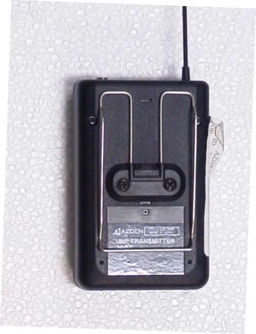
BZB30BT
Oct 31, 2006BELTPACK WIRELESS MICROPHONE
Equipment Class
TBT - Licensed Broadcast Transmitter Worn on Body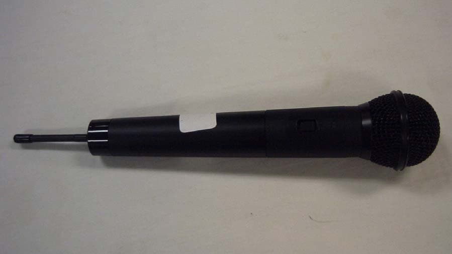
BZB51HT
Aug 04, 2004HANDHELD WIRELESS MICROPHONE
Equipment Class
TBF - Licensed Broadcast Transmitter Held to Face