C5F7NF0008Video Cassette Recorder
WINIA Electronics Co., Ltd.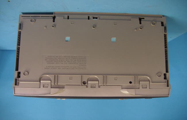
Click to zoom
Application Details
- Equipment Class
- HID - Part 15 TV Interface Device
- Date of Grant
- Dec 25, 2001
- Application Purpose
- Original Equipment
- Date of Application
- Dec 25, 2001
- Equipment Note
- Video Cassette Recorder
- Frequency Range
- 67.25000000 - 71.75000000
- Company
- WINIA Electronics Co., Ltd.
- Country
- South Korea
Documents & Files
Document Text
Text extracted from the exhibit documents filed with the FCC. Open a document above to read the original.
Users Manual
VCR User’s Guide Changing Entertainment. Again. VR637HF 15708270 (VR661HF)(E) 01 CVR2/7/01, 4:55 PM1 This symbol indicates "dangerous voltage" inside the product that presents a risk of electric shock or personal injury. WARNING To reduce the risk of fire or electric shock, do not expose this product to rain or moisture. To reduce the risk of electric shock, do not remove cover (or back). No user serviceable parts inside. Refer servicing to qualified service personnel. This symbol indicates important instructions accompanying the product. Caution: To prevent electric shock, match wide blade of plug to wide slot, fully insert. Attention: Pour éviter les chocs électriques, introduire la lame la plus large de la fiche dans la borne correspondante de la prise et pousser jusqú au fond. Refer to the identification/rating label located on the back panel of your product for its proper operating voltage. FCC Regulations state that unauthorized changes or modifications to this equipment may void the user’s authority to operate it. Cable TV Installer: This reminder is provided to call your attention to Article 820-40 of the National Electrical Code (Section 54 of the Canadian Electrical Code, Part 1) which provides guidelines for proper grounding and, in particular, specifies that the cable ground shall be connected to the grounding system of the building as close to the point of cable entry as practical. Product Registration Please fill out the product registration card and return it immediately. Returning the card allows us to contact you if needed. Keep your sales receipt to obtain warranty parts and service and for proof of purchase. Attach it here and record the serial and model numbers in case you need them. The numbers are located on the back of the VCR. Model No Serial No. _______________________________________________________________________________________ Purchase Date: ___________________________________________________________________________________ Dealer/Address/Phone: ___________________________________________________________________________ Important Information VR637HF i CAUTION RISK OF ELECTRIC SHOCK. DO NOT OPEN. 15708270 (VR661HF)(E) 01 CVR2/7/01, 4:55 PM2 1 Introduction Introduction Key Features Overview Your VCR is equipped with features that will add to your recording and viewing experience. The following information summarizes a few of these features. Chapter 4 provides more information about the rest of the VCR’s features and how to use them. I N P U T T V • V C R ON•OFF PLAYFORWARD RECORD STOPPAUSE F.ADV CLEARMENU SPEED TRACKING 1 4 7 2 5 8 3 6 9 0 C H A N V O L V O L C H A N INFO SEARCH MUTE GO BACK TV VCR REVERSE Rec Ch 36 Record Length 1:30 Press REC to set length VCR Plus+ ® SILVER System The VCR Plus+ system allows for simple timer recording programming by using a single PlusCode® programming number found in most TV program listings. The VCR Plus+ SILVER system simplifies timer recordings by automatically setting up and updating the VCR’s clock and channel list for you. Requirements: Make sure the VCR Plus+ SILVER system is active, and that Auto Channel Search and time set features are correct. ® This feature uses patented technology that detects and marks most commercials on your recordings. The VCR determines where commercials are located, marks the beginnings and ends of detected commercial segments, then easily skips over them during playback. This feature does not erase commercials from the tape. ® This feature helps locate the beginning of a purchased or rented movie as well as skip thorugh previews. You can go to the beginning of the movie, or, skip from one preview/long commercial to the next. Universal Back-Lit Remote Control Description: The VCR’s remote control can operate most RCA, GE, and Proscan TVs with no additional steps. It can be programmed to operate many other brands of TVs. Back-lit buttons offer easier control in the dark. Requirements: Point the remote control at the active component and press the ON•OFF button to see if it can be operated. Auto Clock Set Description: The VCR automatically looks for time and date information after most power outages as well as each time the machine is turned off. Using time information broadcast in TV signals (if available), the VCR’s clock sets itself. Requirements: Start Auto Clock Set using the VCR’s on-screen menus. VCR Plus+ and PlusCode are registered trademarks of the Gemstar Development Corporation. The VCR Plus+ system is manufactured under the license from Gemstar Development Corporation. COMMERCIAL ADVANCE and MOVIE ADVANCE are registered trademarks of SRT, Inc.; a Jerry Iggulden invention licensed in association with Arthur D. Little Enterprises. 15708270 (VR661HF)(E) 02 Intro2/7/01, 4:55 PM1 2 Introduction Express Recording (XPR) Description: XPR quickly records the remaining portion of a program already in progress. XPR is a great way to capture the end of a sporting event that has run into overtime or a live broadcast that runs long. Requirements: Repeatedly press the Record button on the VCR front panel or remote control to set the desired duration of time to record. Pro-Tect Plus™ Locking Description: Locks the VCR so that buttons on the front panel and remote control won’t operate the VCR. This feature protects timer programs from frustrating accidents such as being left on at the time of recording. Requirements: Lock the VCR by pressing and holding the POWER button on the remote control for six seconds. The front panel display will blink for several seconds. The VCR unlocks by pressing and holding the POWER button on the remote control, again for six seconds. The front panel display will blink again and release the lock on the system. Front Audio/Video Input Jacks Description: The VCR has Audio/Video (A/V) input jacks on both the front and rear of the unit (there are output jacks on the rear panel only). The front A/V jacks make it easy to plug in an external A/V device, such as a camcord…
Text truncated - open the document above for the full version.
Users Manual
Chapter 329 Using the Remote Control TV Codes Akai ......................................... 03 AOC ..................................... 06,12 Candle ....................................... 06 Citizen ....................................... 06 Colortyme ................................. 06 Concerto ................................... 06 Curtis Mathes ....................... 01,06 Daewoo ............................... 06,12 Daytron ..................................... 06 Electrohome ........................ 06,12 Emerson .................................... 06 Envision .............................. 05, 06 Fisher .................................. 05, 08 GE .......................... 00, 01, 06, 11 Goldstar ............................... 06,12 Hallmark ................................... 06 Hitachi ................................. 06,14 Infinity ...................................... 04 J C Penney ....... 00, 01, 06, 09, 12 JBL ............................................. 04 Jensen ....................................... 06 JVC ...................................... 10, 11 Kawasho ............................. 03, 06 Kenwood ............................ 06, 12 Loewe ....................................... 04 Luxman ..................................... 06 LXI .................................04, 05, 07 Magnavox ..................... 04, 06, 12 Marantz ............................... 04, 06 MGA .................................... 06, 12 Mitsubishi ........................... 06, 12 MTC .......................................... 06 NAD ........................................... 07 NEC ............................................ 06 Panasonic ...................... 04, 08, 11 Philco ............................. 04, 06, 12 Philips ...................... 03, 04, 06, 12 Pioneer ...................................... 06 Portland ............................... 06, 12 Proscan ...................................... 01 Proton ........................................ 06 Quasar ....................................... 11 Radio Shack ................... 01, 05, 13 RCA ................................ 01, 06, 12 Realistic ...................................... 05 Sampo ........................................ 06 Samsung ........................ 06, 09, 12 Sanyo ................................... 05, 08 Sears ....... 01, 05, 06, 07, 08, 10, 12 Sharp ..................................... 06,13 Sony ........................................... 03 Soundesign ................................ 06 Sylvania .......................... 04, 06, 12 Technics ..................................... 11 Techwood .................................. 06 Teknika ...................................... 06 TMK ........................................... 06 Toshiba .................... 05, 07, 08, 09 Universal .................................... 00 Victor ......................................... 10 Wards ........... 00, 01, 04, 06, 12, 13 Yamaha ...................................... 12 Zenith ........................................ 02 15708270 (VR661HF)(E) 06 Remote2/7/01, 4:56 PM29 30Chapter 3 Using the Remote Control Operating the TV After you set up the remote control, see which buttons operate your TV: 1. Point the remote control at the TV, and press the TV button. If the TV does not turn on, press the TV button and then press the ON •OFF button. 2. You may want to experiment to see which buttons operate your TV. Try pressing buttons, such as VOL and MUTE. See the button descriptions in this chapter for details about what each remote control button does. 15708270 (VR661HF)(E) 06 Remote2/7/01, 4:56 PM30 31 Changing Entertainment. Again. Using the VCR’s Features Chapter Overview: •Recording •Express Recording (XPR) •Timer Recordings •Using the VCR Plus+ System •Copying and Editing Tapes Chapter 4 15708270 (VR661HF)(E) 07 Ftrs2/7/01, 4:56 PM31 VCR Features 32Chapter 4 Recording Features Your VCR provides many ways to capture programming: 1.Recordinglets you press one button to record a program. 2.Express Recording (XPR)allows recording to start while a program is being watched. This feature automatically stops recording after a designated period of time. 3.Timer Recordingprogram the VCR for a daily, weekly, or one-time recording which will automatically start and stop at the times you set. 4.Timer Recording with the VCR Plus+ Systemprogram the VCR by entering a PlusCode programming number found in most TV program listings. Express Recording (XPR) Use XPR to quickly record the remaining portion of a program being watched. XPR is a great way to capture the end of a sporting event that has run into overtime or a live broadcast that runs long. XPR works in 30-minute increments. You can capture the last 30, 60, 90, etc. minutes of programming (depending on tape length), up to four hours total. To Activate XPR: 1. If necessary, turn on the VCR and tune it to the channel with the desired programming. 2. If necessary, insert a tape with its safety tab in place into the VCR. Make sure it is cued to record at the proper starting point. Note: To override the preferred tape speed setting, press the SPEED button on the remote control repeatedly to toggle between SP and SLP choices. 3. Press the RECORD button on the remote control or VCR front panel to start recording. 4. Repeatedly press the RECORD button to set up the recording duration. •Each press of the RECORD button adds 30 minutes of recording time. •The VCR automatically turns off after recording for the set time. •To stop an XPR recording, press and hold the STOP button on the remote control or VCR front panel for several seconds until STOP appears on the VCR on-screen display. Rec Ch 36 Record Length 0:00 Press REC to set length Rec Ch 36 Record Length 1:30 Press REC to set length 15708270 (VR661HF)(E) 07 Ftrs2/7/01, 4:56 PM32 VCR Features Chapter 433 Timer Recording You can program up to eight different broadcasts to be recorded. Notes– In order for a timer recording to…
Text truncated - open the document above for the full version.
Block Diagram
IST Co., Ltd. EMC LABORATORY Block Diagram . Ref. No: 01-IST-179 1 of 5 AUDIO BLOCK DIAGRAM IST Co., Ltd. EMC LABORATORY Block Diagram . Ref. No: 01-IST-179 2 of 5 HI-FI AUDIO BLOCK DIAGRAM IST Co., Ltd. EMC LABORATORY Block Diagram . Ref. No: 01-IST-179 3 of 5 POWER SUPPLY BLOCK DIAGRAM IST Co., Ltd. EMC LABORATORY Block Diagram . Ref. No: 01-IST-179 4 of 5 SERVO & SYSCON BLOCK DIAGRAM IST Co., Ltd. EMC LABORATORY Block Diagram . Ref. No: 01-IST-179 5 of 5 VIDEO BLOCK DIAGRAM
External Photos
IST Co., Ltd. EMC LABORATORY External Photos.Ref.No : 01-IST-179 1 of 3 The DUT photos Front View Rear View IST Co., Ltd. EMC LABORATORY External Photos.Ref.No : 01-IST-179 2 of 3 The DUT photos Side View Side View IST Co., Ltd. EMC LABORATORY External Photos.Ref.No : 01-IST-179 3 of 3 The DUT photos Bottom View CFR 47 Part 15 Sec 15.19 Labeling Requirement “This device complied with.....” Sec 15.21 User Information is described in User manual ‘ Important Information’
ID Label/Location Info
VIDEO CASSETTE RECORDER /MAGNÉTOSCOPE À CASSETTE MODEL/MODÈLE NO.:VR637HF AC/CA 120V/60Hz, 17W FCC ID: C5F7NF0008 MADE IN KOREA FABRIQUÉ EN CORÉE SERIAL /SÉRIE: THOMSON MULTIMEDIA INC. 10330 N. MERIDIAN, INDIANAPOLIS, IN 46290 US LISTED 63JK VIDEO EQUIPMENT E202981 R C
ID Label/Location Info
IST Co., Ltd. EMC LABORATORY Label Location.Ref.No : 01-IST-179 1 of 1 Label Location
Internal Photos
IST Co., Ltd. EMC LABORATORY Internal Photos. Ref.No: 01-IST-179 1 of 17 The DUT photos Deck Top View Deck Bottom View IST Co., Ltd. EMC LABORATORY Internal Photos. Ref.No: 01-IST-179 2 of 17 The DUT photos PCB Parts View PCB Copper View IST Co., Ltd. EMC LABORATORY Internal Photos. Ref.No: 01-IST-179 3 of 17 The DUT photos Top Cover/Inner Front Inner Bottom IST Co., Ltd. EMC LABORATORY Internal Photos. Ref.No: 01-IST-179 4 of 17 Tuner photos(LGTMI-US2-S) Front View Rear View IST Co., Ltd. EMC LABORATORY Internal Photos. Ref.No: 01-IST-179 5 of 17 Tuner photos(LGTMI-US2-S) Inner View Inner View IST Co., Ltd. EMC LABORATORY Internal Photos. Ref.No: 01-IST-179 6 of 17 Tuner photos(ALTMI-US3-S) Front View Rear View IST Co., Ltd. EMC LABORATORY Internal Photos. Ref.No: 01-IST-179 7 of 17 Tuner photos(ALTMI-US3-S) Inner View Inner View IST Co., Ltd. EMC LABORATORY Internal Photos. Ref.No: 01-IST-179 8 of 17 Tuner photos(DWTMI-US3-S) Front View Rear View IST Co., Ltd. EMC LABORATORY Internal Photos. Ref.No: 01-IST-179 9 of 17 Tuner photos(DWTMI-US3-S) Inner View Inner View IST Co., Ltd. EMC LABORATORY Internal Photos. Ref.No: 01-IST-179 10 of 17 Tuner photos(LGTMI-US4-S) Front View Rear View IST Co., Ltd. EMC LABORATORY Internal Photos. Ref.No: 01-IST-179 11 of 17 Tuner photos(LGTMI-US4-S) Inner View Inner View IST Co., Ltd. EMC LABORATORY Internal Photos. Ref.No: 01-IST-179 12 of 17 Tuner photos(SSTMI-US3-S) Front View Rear View IST Co., Ltd. EMC LABORATORY Internal Photos. Ref.No: 01-IST-179 13 of 17 Tuner photos(SSTMI-US3-S) Inner View Inner View IST Co., Ltd. EMC LABORATORY Internal Photos. Ref.No: 01-IST-179 14 of 17 Tuner photos(SATMI-US4-S) Front View Rear View IST Co., Ltd. EMC LABORATORY Internal Photos. Ref.No: 01-IST-179 15 of 17 Tuner photos(SATMI-US4-S) Front View Rear View IST Co., Ltd. EMC LABORATORY Internal Photos. Ref.No: 01-IST-179 16 of 17 Tuner photos(ALTMI-US4-S) Front View Rear View IST Co., Ltd. EMC LABORATORY Internal Photos. Ref.No: 01-IST-179 17 of 17 Tuner photos(ALTMI-US4-S) Inner View Inner View
Test Report
IST Co., Ltd. EMC LABORATORY TEST REPORT NO. : 01-IST-179 1 of 115 Certification of Compliance CFR 47 Part 15 Subpart B Test Report File No. : 01-IST-179 Date of Issue : Dec. 19,2001 Model(s) : DV-T8G5N-PQ / DAEWOO : VR637HF / Thomson Kind of Product : Video Cassette Recorder (TV Interface Device) Applicant : Daewoo Electronics Co., Ltd. Address : 543, Dangjung-Dong, Kunpo-City, Kyonggi-Do 435-030, Korea Manufacturer : Daewoo Electronics Co., Ltd. Address : 295, Gondan-dong, Kumi-city, Kyungsangbuk-do, Korea Test Result Positive Negative Reviewed By Approved By J.H. Lee / General Manager G. Chung / Chief - The test report with appendix consists of 115 pages. - The test result only responds to the tested sample. - It is not allowed to copy this report even partly without the allowance of IST EMC Laboratory. - This equipment as for has been shown to be capable of continued compliance with the applicable technical standards as indicated in the measurement report and was tested in accordance with the measurement procedures specified in ANSI C63.4 1992. IST Co., Ltd. EMC LABORATORY TEST REPORT NO. : 01-IST-179 2 of 115 TABLE OF CONTENTS Table of contents 2 Information of test laboratory, Environmental condition, Power used 3 Descriptions of test 4-6 Conducted Emission 4 Radiated Emission 5 Output Signal level measurements 6 Output Terminal Conducted Spurious Emission 6 Transfer Switch Isolation Measurement 6 Summary 7 Test Conditions and Data - Emission Conducted Emission 0.45MHz - 30MHz Test equipment / Data and Plots 8-36 Radiated Emission 30MHz - 1GHz Test equipment / Data and Plots 37-38 Output Signal level measurements Test equipment / Data and Plots 39-74 Output Terminal Conducted Spurious Emission 30MHz - 1GHz Test equipment / Data and Plots 75-91 Transfer Switch Isolation Measurement 30MHz - 1GHz Test equipment / Data and Plots 92-108 Information OF TUNERS Manufacture Manufacture Name Daewoo Model Name LG Innotek TADC-H101F LGTMI-US2-S Alps KOREA TMDH2-A50A ALTMI-US3-S Partsnic DTMI-5NF03 DWTMI-US3-S LG Innotek TADC-H301F LGTMI-US4-S SAMSUNG TCMN0682PA13B SSTMI-US3-S SANYO VD065AW SATMI-US4-S ALPS KOREA TMZH2-004A ALTMI-US4-S Appendix A. The preliminary test results 109 -115 IST Co., Ltd. EMC LABORATORY TEST REPORT NO. : 01-IST-179 3 of 115 INFORMATIONS OF TEST LABORATORY EMC LABORATORY of IST Co., Ltd.(FCC Filing Lab) San 21-8, Goan-Ri, Baekam-Myun, Yongin-City Kyonggi-Do, 449-860, Korea TEL : +82 31 333 4093 FAX : +82 31 333 4094 ENVIRONMENTAL CONDITIONS Temperature 9 Humidity 40 % Atmospheric pressure 999 mbar POWER SUPPLY SYSTEM USED Power supply system 120 Vac , 60 Hz PRODUCT INFORMATIONS Power supply system 120Vac / 60Hz Power consumption 17W Video signal EIA STANDARD NTSC COLOR RF input impedance 75 ohm Unbal. (U/V one input) RF output impedance 75 ohm Unbal. VHF output signal Channel 3 or 4 (selectable) Video input signal Phono type 1.0 0.2Vp-p sync negative 75ohms unbalance Video output signal Phono type 1.0 0.2Vp-p sync negative 75ohms unbalance Audio input signal Phono type, -8.8dBm, more then 47k ohms unbalanced Audio output signal Phono type, -5.8dBm, less then 1k ohms unbalanced Dimension 360 91 238 (WHD) - EMC suppression device is not used during the test. - Please refer to user’s manual. IST Co., Ltd. EMC LABORATORY TEST REPORT NO. : 01-IST-179 4 of 115 DESCRIPTIONS OF TEST Conducted Emissions: The measurement were performed over the frequency range of 0.45MHz to 30MHz using a 50/50uH LISN as the input transducer to a Spectrum Analyzer or a Field Intensity Meter. The measurements were made with the detector set for "Peak" amplitude within an bandwidth of 10KHz or for "quasi-peak" within a bandwidth of 9KHz. - Procedure of Test The line-conducted facility is located inside a shielded room No.1. A 1m X 1.5m wooden table 80cm height is placed 40cm away from the vertical wall and 1.5m away from the other wall of the shielded room. The R/S ESH3-Z5 and EMCO 3825/2 LISN are bonded to bottom of the shielded room. The EUT is located on the wooden table with distance more than 80cm from the LISN and powered from the EMCO LISN .The peripheral equipment is powered from the other LISN. Power to the LISNs are filtered by a noise cut power line filters. All electrical cables are shielded by braided tinned steel tubing with inner φ 1.2cm. If the EUT is a DC-powered device, power will be derived from the source power supply it normally will be powered from and this supply lines will be connected to the EMCO LISN. All interconnecting cables more than 1m were shortened by non-inductive bundling to a 1m length. Sufficient time for the EUT, support equipment, and test equipment was allowed in order for them to warm up to their normal operating conditions. The RF output of the LISN was connected to the R/S receiver to determine the frequency producing the maximum emission from the EUT. The frequency producing the maximum level was reexamined using Quasi-Peak mode by manual measurement, after scanned by automatic Peak mode for frequency range from 0.45 to 30MHz. The bandwidth of the receiver was set to 10kHz. The EUT, peripheral equipment, and interconnecting cables were arranged and manipulated to maximize each EME emission. 215 >150>40 80 Receiver EUT LISN 80 ≥ 80 80 40 ≥ 80 Measuring apparatus Mains Filter Mains Front side Equipment under test Coaxial cable Artificial mains network Screened room Non-metallic support 80 < Side View > < Concept Drawing > IST Co., Ltd. EMC LABORATORY TEST REPORT NO. : 01-IST-179 5 of 115 DESCRIPTION OF TEST Radiated Emissions: The measurement was performed over the frequency range of 30MHz to 1GHz using antenna as the input transducer to a Spectrum analyzer or a Field Intensity Meter. The measurement was made with the detector set for "quasi-peak" within a bandwidth of 120KHz. - Procedure of Test Preliminary measurements were made at 3 meter using bi-conical and log-periodic antennas, and spectrum analyzer to determine the frequency producing the max. emiss…
Text truncated - open the document above for the full version.
Test Report
IST Co., Ltd. EMC LABORATORY TEST REPORT NO. : 01-IST-179 61 of 115 Output Signal Level Measurements Tuner: LGTMI-US4-S CH4 Play (Pix) CH4 Play (Aud) IST Co., Ltd. EMC LABORATORY TEST REPORT NO. : 01-IST-179 62 of 115 Output Signal Level Measurements Tuner: LGTMI-US4-S CH4 Record (Pix) CH4 Record (Aud) IST Co., Ltd. EMC LABORATORY TEST REPORT NO. : 01-IST-179 63 of 115 Output Signal Level Measurements Tuner: SSTMI-US3-S CH3 Play (Pix) CH3 Play (Aud) IST Co., Ltd. EMC LABORATORY TEST REPORT NO. : 01-IST-179 64 of 115 Output Signal Level Measurements Tuner: SSTMI-US3-S CH3 Record (Pix) CH3 Record (Aud) IST Co., Ltd. EMC LABORATORY TEST REPORT NO. : 01-IST-179 65 of 115 Output Signal Level Measurements Tuner: SSTMI-US3-S CH4 Play (Pix) CH4 Play (Aud) IST Co., Ltd. EMC LABORATORY TEST REPORT NO. : 01-IST-179 66 of 115 Output Signal Level Measurements Tuner: SSTMI-US3-S CH4 Record (Pix) CH4 Record (Aud) IST Co., Ltd. EMC LABORATORY TEST REPORT NO. : 01-IST-179 67 of 115 Output Signal Level Measurements Tuner: SATMI-US4-S CH3 Play (Pix) CH3 Play (Aud) IST Co., Ltd. EMC LABORATORY TEST REPORT NO. : 01-IST-179 68 of 115 Output Signal Level Measurements Tuner: SATMI-US4-S CH3 Record (Pix) CH3 Record (Aud) IST Co., Ltd. EMC LABORATORY TEST REPORT NO. : 01-IST-179 69 of 115 Output Signal Level Measurements Tuner: SATMI-US4-S CH4 Play (Pix) CH4 Play (Aud) IST Co., Ltd. EMC LABORATORY TEST REPORT NO. : 01-IST-179 70 of 115 Output Signal Level Measurements Tuner: SATMI-US4-S CH4 Record (Pix) CH4 Record (Aud) IST Co., Ltd. EMC LABORATORY TEST REPORT NO. : 01-IST-179 71 of 115 Output Signal Level Measurements Tuner: ALTMI-US4-S CH3 Play (Pix) CH3 Play (Aud) IST Co., Ltd. EMC LABORATORY TEST REPORT NO. : 01-IST-179 72 of 115 Output Signal Level Measurements Tuner: ALTMI-US4-S CH3 Record (Pix) CH3 Record (Aud) IST Co., Ltd. EMC LABORATORY TEST REPORT NO. : 01-IST-179 73 of 115 Output Signal Level Measurements Tuner: ALTMI-US4-S CH4 Play (Pix) CH4 Play (Aud) IST Co., Ltd. EMC LABORATORY TEST REPORT NO. : 01-IST-179 74 of 115 Output Signal Level Measurements Tuner: ALTMI-US4-S CH4 Record (Pix) CH4 Record (Aud) IST Co., Ltd. EMC LABORATORY TEST REPORT NO. : 01-IST-179 75 of 115 TEST CONDITIONS AND DATA Output Terminal Conducted Spurious Emission Test Equipment Used Model Name Manufacturer Description Next Cal. Date 8566B Hewlett Packard Spectrum Analyzer Jul. 13, 2002 85685A Hewlett Packard RF preselector Jul. 13, 2002 RAM Rohde & Schwarz Matching Pad Sep. 21, 2002 PM5515 Philips Pattern Generator Jun. 20, 2002 External Peripherals Device Description Model Name Manufacture FCC Compliance Information TV Receiver F19430 Daewoo Verification Test Program Normal operating mode(Play and record mode) Test Area Compact Chamber Note : Limit Calculation (Sec 15.115(b)(2)(ii)) 10.95 X 75 1/2 uV = 95uV =39.55 dBuV plus 30dB = 69.55dBuV = -37.45dBm Find the test data in following page(s) 76 to 91. IST Co., Ltd. EMC LABORATORY TEST REPORT NO. : 01-IST-179 76 of 115 Output Terminal Conducted Spurious Emission TV CH Freq.(MHz) Level(dBuV) Limit(dBuV) Mode Margin(dB) 3 61.00 55.90 69.55 Play -13.65 3 61.00 55.80 69.55 Record -13.75 4 66.90 55.90 69.55 Play -13.65 4 66.90 55.50 69.55 Record -14.05 Spurious Emission Tabulated Data with Tuner (LG Innotek Co., Ltd. Model: LGTMI-US2-S) TV CH Freq.(MHz) Level(dBuV) Limit(dBuV) Mode Margin(dB) 3 61.00 56.80 69.55 Play -12.75 3 61.00 55.10 69.55 Record -14.45 4 66.90 54.50 69.55 Play -15.05 4 66.90 54.50 69.55 Record -15.05 Spurious Emission Tabulated Data with Tuner (Korea Alps Model: ALTMI-US3-S) TV CH Freq.(MHz) Level(dBuV) Limit(dBuV) Mode Margin(dB) 3 61.00 57.60 69.55 Play -11.95 3 61.00 59.00 69.55 Record -10.55 4 66.90 57.30 69.55 Play -12.25 4 66.90 57.60 69.55 Record -11.95 Spurious Emission Tabulated Data with Tuner (Partsnic Model: DWTMI-US3-S) TV CH Freq.(MHz) Level(dBuV) Limit(dBuV) Mode Margin(dB) 3 61.00 56.20 69.55 Play -13.35 3 61.00 57.40 69.55 Record -12.15 4 66.90 55.90 69.55 Play -13.65 4 66.90 56.00 69.55 Record -13.55 Spurious Emission Tabulated Data with Tuner (LG Innotek Co., Ltd. Model: LGTMI-US4-S) IST Co., Ltd. EMC LABORATORY TEST REPORT NO. : 01-IST-179 77 of 115 Output Terminal Conducted Spurious Emission TV CH Freq.(MHz) Level(dBuV) Limit(dBuV) Mode Margin(dB) 3 61.00 56.30 69.55 Play -13.25 3 61.00 56.40 69.55 Record -13.15 4 66.90 57.50 69.55 Play -12.05 4 66.90 56.00 69.55 Record -13.55 Spurious Emission Tabulated Data with Tuner (Samsung Electronic Co., Ltd. Model: SSTMI-US3-S) TV CH Freq.(MHz) Level(dBuV) Limit(dBuV) Mode Margin(dB) 3 61.00 56.80 69.55 Play -12.75 3 61.00 56.70 69.55 Record -12.85 4 66.90 56.60 69.55 Play -12.85 4 66.90 56.50 69.55 Record -13.05 Spurious Emission Tabulated Data with Tuner (Sanyo Electronic Co., Ltd. Model: SATMI-US4-S) TV CH Freq.(MHz) Level(dBuV) Limit(dBuV) Mode Margin(dB) 3 61.00 55.70 69.55 Play -13.85 3 61.00 55.50 69.55 Record -14.05 4 66.90 56.50 69.55 Play -13.05 4 66.90 55.00 69.55 Record -14.55 Spurious Emission Tabulated Data with Tuner (Korea Alps Model: ALTMI-US4-S) IST Co., Ltd. EMC LABORATORY TEST REPORT NO. : 01-IST-179 78 of 115 Output Terminal Conducted Spurious Emission Tuner: LGTMI-US2-S CH3 Play CH3 Record IST Co., Ltd. EMC LABORATORY TEST REPORT NO. : 01-IST-179 79 of 115 Output Terminal Conducted Spurious Emission Tuner: LGTMI-US2-S CH4 Play CH4 Record IST Co., Ltd. EMC LABORATORY TEST REPORT NO. : 01-IST-179 80 of 115 Output Terminal Conducted Spurious Emission Tuner: ALTMI-US3-S CH3 Play CH3 Record IST Co., Ltd. EMC LABORATORY TEST REPORT NO. : 01-IST-179 81 of 115 Output Terminal Conducted Spurious Emission Tuner: ALTMI-US3-S CH4 Play CH4 Record IST Co., Ltd. EMC LABORATORY TEST REPORT NO. : 01-IST-179 82 of 115 Output Terminal Conducted Spurious Emission Tuner: DWTMI-US3-S CH3 Play CH3 Record IST Co., Ltd. EMC LABORATORY TEST REPORT NO. : 01-IST-179 83 of 115 Output Terminal Conducted Spurious Emission Tuner: DWTMI-US3-S CH4 Play CH4 Record IST Co., Ltd. EMC LABORATORY TEST REPORT NO. :…
Text truncated - open the document above for the full version.
Test Report
IST Co., Ltd. EMC LABORATORY TEST REPORT NO. : 01-IST-179 86 of 115 Output Terminal Conducted Spurious Emission Tuner: SSTMI-US3-S CH3 Play CH3 Record IST Co., Ltd. EMC LABORATORY TEST REPORT NO. : 01-IST-179 87 of 115 Output Terminal Conducted Spurious Emission Tuner: SSTMI-US3-S CH4 Play CH4 Record IST Co., Ltd. EMC LABORATORY TEST REPORT NO. : 01-IST-179 88 of 115 Output Terminal Conducted Spurious Emission Tuner: SATMI-US4-S CH3 Play CH3 Record IST Co., Ltd. EMC LABORATORY TEST REPORT NO. : 01-IST-179 89 of 115 Output Terminal Conducted Spurious Emission Tuner: SATMI-US4-S CH4 Play CH4 Record IST Co., Ltd. EMC LABORATORY TEST REPORT NO. : 01-IST-179 90 of 115 Output Terminal Conducted Spurious Emission Tuner: ALTMI-US4-S CH3 play CH3 Record IST Co., Ltd. EMC LABORATORY TEST REPORT NO. : 01-IST-179 91 of 115 Output Terminal Conducted Spurious Emission Tuner: ALTMI-US4-S CH4 Play CH4 Record IST Co., Ltd. EMC LABORATORY TEST REPORT NO. : 01-IST-179 92 of 115 TEST CONDITIONS AND DATA Transfer Switch Isolation Measurement Test Equipment Used Model Name Manufacturer Description Next Cal. Date 8566B Hewlett Packard Spectrum Analyzer Jul. 13, 2002 85685A Hewlett Packard RF preselector Jul. 13, 2002 RAM Rohde & Schwarz Matching Pad Sep. 21, 2002 PM5515 Philips Pattern Generator Jun. 20, 2002 External Peripherals Device Description Model Name Manufacture FCC Compliance Information TV Receiver F19430 Daewoo Verification Test Program Normal operating mode(Play and record mode) Test Area Compact Chamber Note : Transfer switch isolation measurements were made on the Channel 3 and 4 video output frequencies of 61.25 and 67.25 MHz and both position of the transfer switch. Limit calculation(Sec 15.115 (c)(1)(ii)) 0.346 X 75 1/2 = 2.996uV = 9.53dBuV = -97.46dBm Find the test data in following page(s) 93 to 108. IST Co., Ltd. EMC LABORATORY TEST REPORT NO. : 01-IST-179 93 of 115 Transfer Switch Isolation Measurement TV CH Freq.(MHz) Level(dBuV) Limit(dBuV) Mode Margin(dB) 3 61.25 5.62 9.53 Play -3.91 3 61.25 5.60 9.53 Record -3.93 4 67.25 6.01 9.53 Play -3.52 4 67.25 5.97 9.53 Record -3.56 Transfer Switch Tabulated Data with Tuner (LG Innotek Co., Ltd. Model: LGTMI-US2-S) TV CH Freq.(MHz) Level(dBuV) Limit(dBuV) Mode Margin(dB) 3 61.25 5.54 9.53 Play -3.99 3 61.25 5.51 9.53 Record -4.02 4 67.25 6.12 9.53 Play -3.41 4 67.25 6.05 9.53 Record -3.48 Transfer Switch Tabulated Data with Tuner (Korea Alps Model: ALTMI-US3-S) TV CH Freq.(MHz) Level(dBuV) Limit(dBuV) Mode Margin(dB) 3 61.25 5.72 9.53 Play -3.81 3 61.25 5.70 9.53 Record -3.62 4 67.25 5.91 9.53 Play -3.62 4 67.25 5.86 9.53 Record -3.67 Transfer Switch…
Text truncated - open the document above for the full version.
Contact Information
Applicant
Youjin Choi(Manager)
Test Firm
IST Co., LtdBong Kyoon Bae
Technical Specifications
| # | Rule Parts | Frequency Range | Power Output |
|---|---|---|---|
| 2 | 15B | 67.25 MHz - 71.75 MHz | - |
Other Applications from WINIA Electronics Co., Ltd.
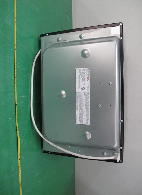
C5F7NF1CMO900N
Nov 23, 2014Microwave Oven
Equipment Class
8CC - Part 18 Consumer Device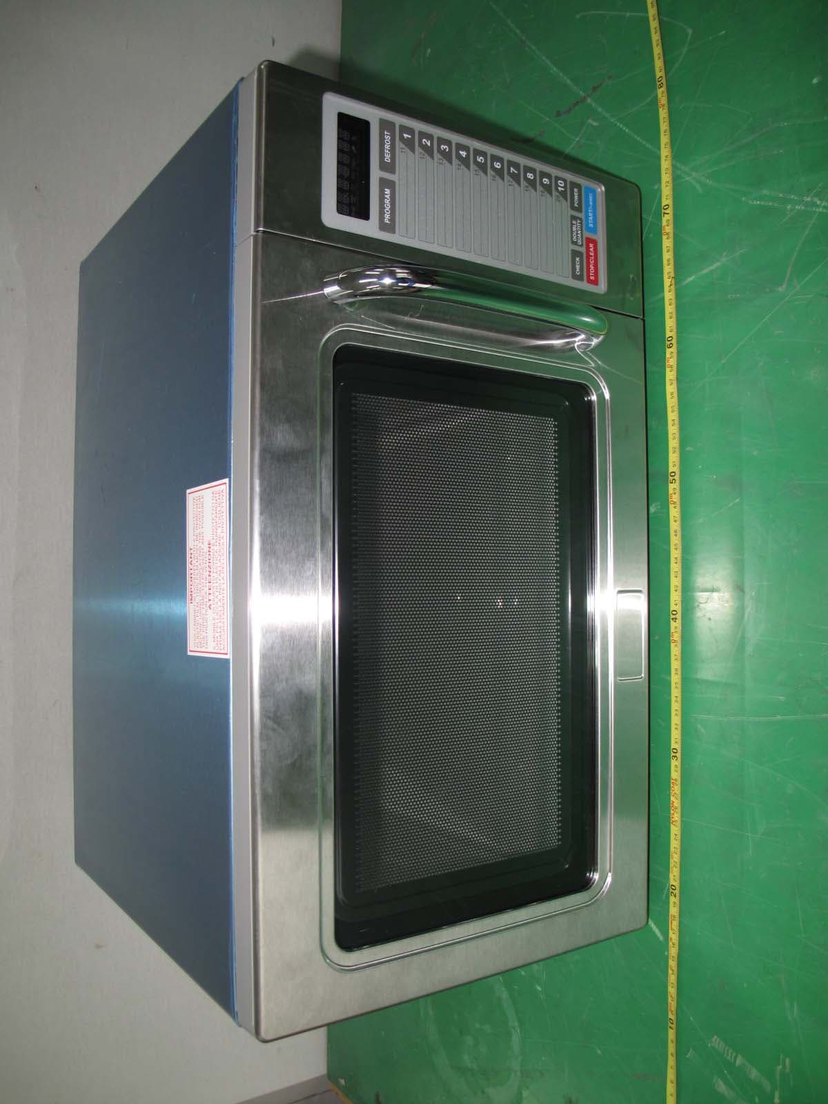
C5F7NF9PMO100N
Mar 25, 2013Commercial Microwave Oven
Equipment Class
8CC - Part 18 Consumer Device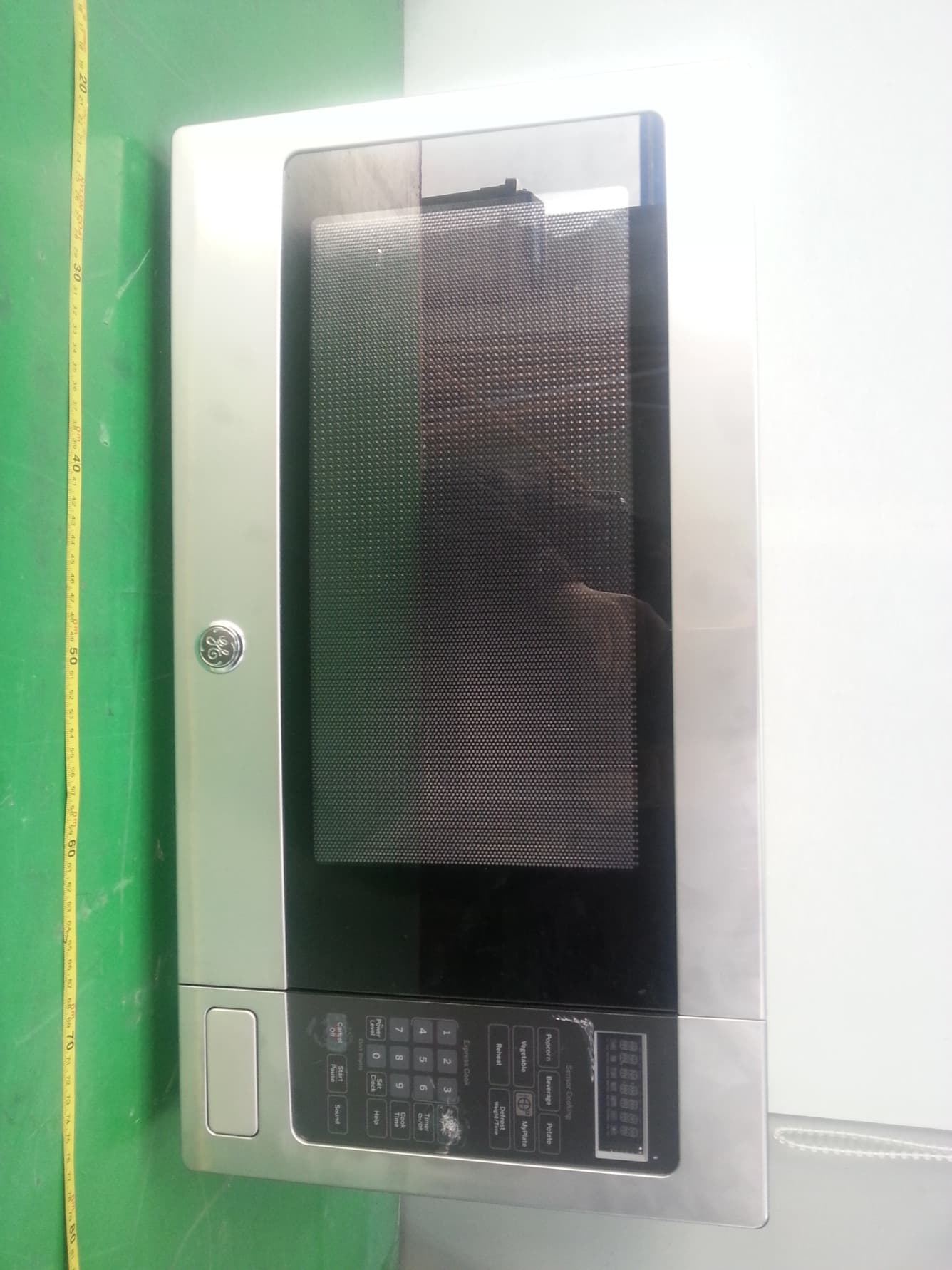
C5F7NF22MO110N
Jan 23, 2013Microwave Oven
Equipment Class
8CC - Part 18 Consumer Device
C5F7NF9FMO120N
May 06, 2012Commercial Microwave Oven
Equipment Class
8CC - Part 18 Consumer Device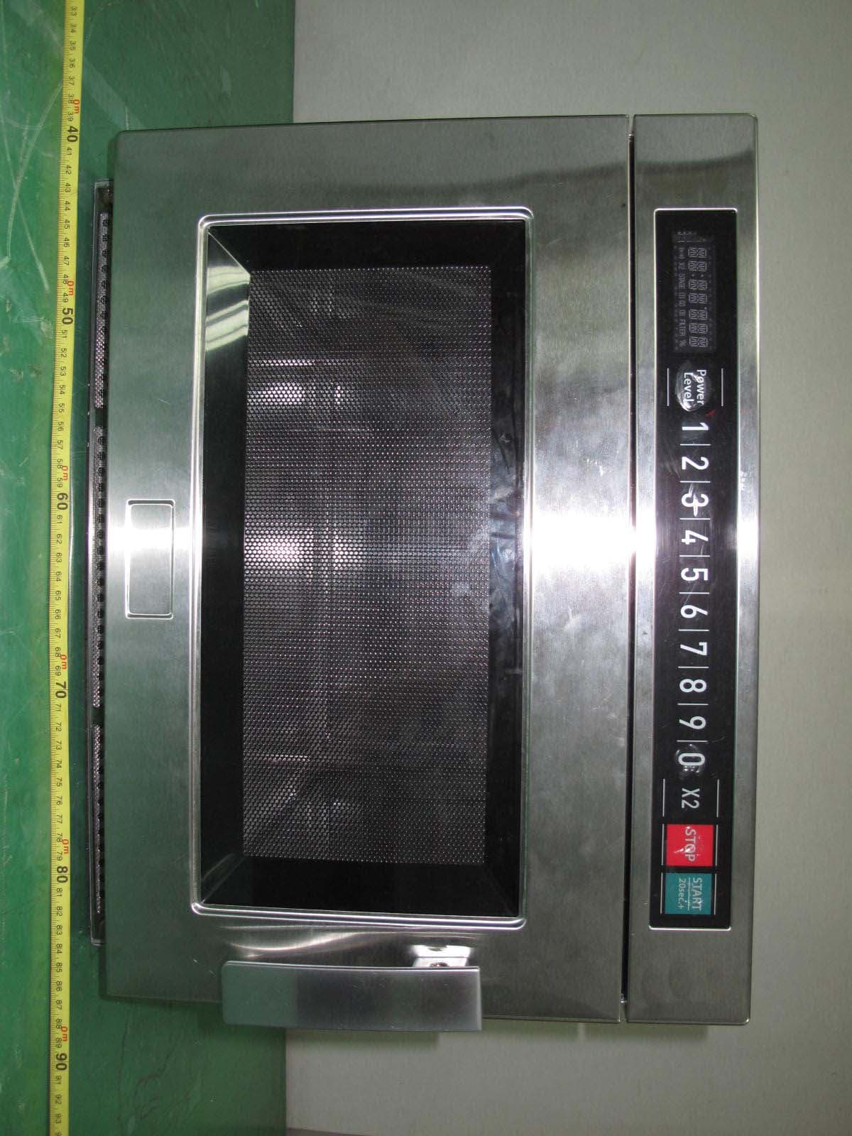
C5F7NF9FMO180N
Sep 05, 2011Commercial Microwave Oven
Equipment Class
8CC - Part 18 Consumer Device