C5F7NF9FMO120NCommercial Microwave Oven
WINIA Electronics Co., Ltd.
Click to zoom
Application Details
- Equipment Class
- 8CC - Part 18 Consumer Device
- Date of Grant
- May 06, 2012
- Application Purpose
- Original Equipment
- Date of Application
- May 06, 2012
- Equipment Note
- Commercial Microwave Oven
- Frequency Range
- 2400.00000000 - 2500.00000000
- Company
- WINIA Electronics Co., Ltd.
- Country
- South Korea
Documents & Files
Document Text
Text extracted from the exhibit documents filed with the FCC. Open a document above to read the original.
Users Manual
VVIISSIIOONN CCRREEAATTIIVVEE,, IINNCC.. 서울 종로구 통의동 6번지 이룸빌딩 4층 ABOUT THIS MANUAL ABOUT THIS MANUAL 담담당당 방요섭 님 브브랜랜드드 DAEWOO 언언어어 영어 FF.. MMOODDEELL KOM-9F0CTX / 9F0CDA BB.. MMOODDEELL KOM-9F0CTX / 9F0CDA BB UU YY EE RR 영문기본 CCOOUUNNTTRRYY 인인쇄쇄 MMEEMMOO 총28p 연락처 VISION 담당 방문수 TEL:730-0660 FAX:730-3788 11.08.12-표지, 1p, 2p, 3p, 4p, 5p, 6p _ 신규7p 11.09.07-1p, 2p, 9p, 23p, 28p(보증서추가)수정_ 신규5p 11.09.09-3p, 4p, 5p, 16p, 17p, 19p, 20p, 21p, 23p, 24p, 27p, 28p 수정_ 신규12p 11.10.13-3p, 9p 수정_ 신규2p Before operating this oven, please read these instructions completely. OPERATING INSTRUCTIONS MICROWAVE OVEN KOM-9F0CTX / 9F0CDA FOR COMMERCIAL USE 1 PRECAUTIONS TO AVOID POSSIBLE EXPOSURETO EXCESSIVE MICROWAVE ENERGY (a)Do not attempt to operate this oven with the door open since open-door operation can result in harmful exposure to microwave energy. It is important not to defeat or tamper with the safety interlocks. (b)Do not place any objectbetween the oven front face and the door or allow soil or cleaner residue to accumulate on sealing surfaces. (c)Do not operate the oven if it is damaged. It is particularly important that the oven door close properly and that there is no damage to the: (1) door (bent), (2) hinges and latches (broken or loosened), (3) door seals and sealing surfaces. (d)The oven should not be adjusted or repaired by anyone except properly qualified service personnel. PRECAUTIONS TO AVOID POSSIBLE EXPOSURETO EXCESSIVE MICROWAVE ENERGY......1 IMPORTANT SAFETY INSTRUCTIONS............................................................................................2 INSTALLATION ..................................................................................................................................3 FEDERAL COMMUNICATIONS COMMISSION RADIO FREQUENCY INTERFERENCE STATEMENT..5 GROUNDING INSTRUCTIONS .........................................................................................................5 SPECIFICATIONS ..............................................................................................................................6 FEATURES DIAGRAM .......................................................................................................................7 FEATURES DIAGRAM (continued) ...................................................................................................8 OPERATION PROCEDURE...............................................................................................................9 CONTROLS ......................................................................................................................................10 Manual Cooking...........................................................................................................................10 Preprogrammed Pads..................................................................................................................11 Double Quantity ...........................................................................................................................12 Programming Pads ......................................................................................................................13 Programming Cook Factor...........................................................................................................14 20 sec.+ pad ................................................................................................................................15 Changing User Options ...............................................................................................................16 COOKING INSTRUCTIONS .............................................................................................................17 MICROWAVING PRINCIPLES .........................................................................................................18 HOW MICROWAVES COOK FOOD ................................................................................................18 CONVERSION CHARTS ..................................................................................................................18 COOKING TECHNIQUES ................................................................................................................19 DEFROSTING GUIDE ......................................................................................................................20 DEFROST AND COOKING CHART.................................................................................................21 CARE OF YOUR MICROWAVE OVEN............................................................................................23 CLEANING AND MAINTENANCE....................................................................................................23 CLEANING THE CEILING COVER ..................................................................................................24 CLEANING THE AIR FILTER ...........................................................................................................24 USE YOUR MICROWAVE OVEN SAFELY .....................................................................................25 BEFORE YOU CALL FOR SERVICE ...............................................................................................26 QUESTIONS AND ANSWERS .........................................................................................................26 QUESTIONS AND ANSWERS (continued) .....................................................................................27 DISPOSAL OF USED ELECTRICAL & ELECTRONIC EQUIPMENT..............................................27 TABLE OF CONTENTS 2 IMPORTANT SAFETY INSTRUCTIONS When using electrical appliances, basic safety precautions should be followed, including the following: WARNING - To reduce the risk of burns, electric shock, fire, injury to persons or exposure to excessive microwave energy: 11. Read all instructions before using the appliance. 12. Read and follow the specific “PRECAUTION…
Text truncated - open the document above for the full version.
Block Diagram
FCC ID: C5F7NF9FMO12ØN Note: Components outlined with dotted line is optional and may not be employed in the model Lamp H.V. CapacitorH.V. Transformer Fan Motor Heating Element Turntable Motor H.V. Diode Magnetron Oven Cavity BLOCK DIAGRAM Input 120Vac 60Hz Conrol Panel (Clock Frequency 4MHz) Turntable Motor H.V. CapacitorH.V. Transformer H.V. Diode Magnetron
External Photos
Test Report No.: NK-12-E-204 FCC Certification Daewoo Electronics Corporation FCC ID: C5F7NF9FMO120N Page 49 of 69 APPENDIX C – EUT PHOTOGRAPHS Front View of EUT Test Report No.: NK-12-E-204 FCC Certification Daewoo Electronics Corporation FCC ID: C5F7NF9FMO120N Page 50 of 69 Rear View of EUT
ID Label/Location Info
Test Report No.: NK-12-E-204 FCC Certification Daewoo Electronics Corporation FCC ID: C5F7NF9FMO120N Page 44 of 69 APPENDIX A – SAMPLE LABEL The sample label shown shall be permanently affixed at a conspicuous location on the device and be readily visible to the user at the time of purchase. FCC ID Location of EUT Labeling Requirements
Internal Photos
Test Report No.: NK-12-E-204 FCC Certification Daewoo Electronics Corporation FCC ID: C5F7NF9FMO120N Page 51 of 69 Door open View of EUT Test Report No.: NK-12-E-204 FCC Certification Daewoo Electronics Corporation FCC ID: C5F7NF9FMO120N Page 52 of 69 Left View of Inside Test Report No.: NK-12-E-204 FCC Certification Daewoo Electronics Corporation FCC ID: C5F7NF9FMO120N Page 53 of 69 Right View of Inside Test Report No.: NK-12-E-204 FCC Certification Daewoo Electronics Corporation FCC ID: C5F7NF9FMO120N Page 54 of 69 Top View of Inside Test Report No.: NK-12-E-204 FCC Certification Daewoo Electronics Corporation FCC ID: C5F7NF9FMO120N Page 55 of 69 Front View of Magnetron Test Report No.: NK-12-E-204 FCC Certification Daewoo Electronics Corporation FCC ID: C5F7NF9FMO120N Page 56 of 69 Rear View of Magnetron Test Report No.: NK-12-E-204 FCC Certification Daewoo Electronics Corporation FCC ID: C5F7NF9FMO120N Page 57 of 69 Front View of Main Board Test Report No.: NK-12-E-204 FCC Certification Daewoo Electronics Corporation FCC ID: C5F7NF9FMO120N Page 58 of 69 Rear View of Main Board Test Report No.: NK-12-E-204 FCC Certification Daewoo Electronics Corporation FCC ID: C5F7NF9FMO120N Page 59 of 69 Front View of Display Board Test Report No.: NK-12-E-204 FCC Certification Daewoo Electronics Corporation FCC ID: C5F7NF9FMO120N Page 60 of 69 Rear View of Display Board Test Report No.: NK-12-E-204 FCC Certification Daewoo Electronics Corporation FCC ID: C5F7NF9FMO120N Page 61 of 69 Front View of Filter Board Test Report No.: NK-12-E-204 FCC Certification Daewoo Electronics Corporation FCC ID: C5F7NF9FMO120N Page 62 of 69 Rear View of Filter Board Test Report No.: NK-12-E-204 FCC Certification Daewoo Electronics Corporation FCC ID: C5F7NF9FMO120N Page 63 of 69 Front View of Trans Test Report No.: NK-12-E-204 FCC Certification Daewoo Electronics Corporation FCC ID: C5F7NF9FMO120N Page 64 of 69 Rear View of Trans Test Report No.: NK-12-E-204 FCC Certification Daewoo Electronics Corporation FCC ID: C5F7NF9FMO120N Page 65 of 69 Label View of Trans Test Report No.: NK-12-E-204 FCC Certification Daewoo Electronics Corporation FCC ID: C5F7NF9FMO120N Page 66 of 69 Enclosure View of Capacitor
Operational Description
Model : KOM-9F0CDA (FCC ID : C5F7NF9FMO120N) ■ OPERATION DESCRIPTION After suppling main power to microwave oven, press start button, then low voltage circui supply DC 5V to the micom in control panel. The micom makes 2-main relays keep on-state in sequency, and makes 2-seperated high voltage circuit for each magnetron. This high voltage circuit consists of combination of H.V Transformer, H.V Capacitor and H.V Diode, and generats about DC 4kV. This high voltage is supplied to each magnetron of top and buttom. Microwave generated by magnetrons and guided to the oven cavity.
Parts List/Tune Up Info
Parts Manufacturer 1 MAGNETRONToshiba 2 TRANS H.V.DPC 3 CAPACITOR H.V.Elcomtec 4 DIODE H.V.Frontier 5 FAN MOTOROh Sung 6 STIRRER MOTORElensys 7 INTERLOCK SWITCHSeveral SPEC. 2M303 0BB-1509X1 120V 60Hz SM16F 20V, 3W 16 A, 125/250 V ac ■ Electrical Components (FCC ID : C5F7NF9FMO120N) DYCR70X0-9FT 2300VAC 0.77UF HV03-12 400MA 12000V
Schematics
Wiring Diagram ( SCHEMATICS ) FCC ID: C5F7NF9FMO12ØN
Test Report
Test Report No.: NK-12-E-204 FCC Certification Daewoo Electronics Corporation FCC ID: C5F7NF9FMO120N Page 2 of 69 TABLE OF CONTENTS SCOPE INTRODUCTION (Site Description) EUT INFORMATION DESCRIPTION OF TESTS (Radiation Hazard) DESCRIPTION OF TESTS (Input Power Measurement) DESCRIPTION OF TESTS (RF Output Power Measurement) DESCRIPTION OF TESTS (Operating Frequency Measurements) DESCRIPTION OF TESTS (Conducted Emissions) DESCRIPTION OF TESTS (Radiated Emissions) TEST DATA (Radiation Hazard) TEST DATA (Input Power Measurement) TEST DATA (RF Output Power Measurement) TEST DATA (Operating Frequency Measurements) TEST DATA (Conducted Emissions) TEST DATA (Radiated Emissions) PLOT OF EMISSIONS (Operating Frequency Measurements) PLOT OF EMISSIONS (Conducted Emissions Diagram) PLOT OF EMISSIONS (Radiated Emissions Diagram) ACCURACY OF MEASUREMENT LIST OF TEST EQUIPMENT APPENDIX A - SAMPLE LABEL APPENDIX B - PHOTOGRAPHS OF TEST SET-UP APPENDIX C - EUT PHOTOGRAPHS APPENDIX D - SCHEMATIC DIAGRAM APPENDIX E - USER’S MANUAL APPENDIX F - BLOCK DIAGRAM 3 4 5 6 6 6 6 7 8 9 9 9 10 12 13 16 34 36 38 43 44 45 49 67 68 69 Test Report No.: NK-12-E-204 FCC Certification Daewoo Electronics Corporation FCC ID: C5F7NF9FMO120N Page 3 of 69 SCOPE Measurement and determination of electromagnetic emissions (EME) of radio frequency devices including intentional and/or unintentional radiators for compliance with the technical rules and regulations of the Federal Communications Commission under FCC part 18. Responsible Party : Contact Person : Manufacturer : Factory : Daewoo Electronics Corporation Mr. Seongok Kim Tel No.: + 82 32 510 7919 Daewoo Electronics Corporation Kitchen Appliances Div. R&D Center, 412-2, Cheongcheon2-Dong, Bupyeong-Gu, Incheon, 403-032, Korea 1) Daewoo Microwave Oven Co., Ltd. Dagang, District, Development Area Tianjin, China 2) INA Inc. 729-6, Ancheong-dong, Gwangsan-gu, Gwangju, Korea FCC ID: C5F7NF9FMO120N Model: KOM-9F0CDA Brand Name: DAEWOO EUT Type: Commercial Microwave Oven Applied Standard: Test Procedure(s): Dates of Test: Place of Tests: Test Report No.: FCC Part 18 & Part 2 MP-5:1986 February 21, 2012 to May 03, 2012 Nemko Korea Co., Ltd. EMC Site NK-12-E-204 Test Report No.: NK-12-E-204 FCC Certification Daewoo Electronics Corporation FCC ID: C5F7NF9FMO120N Page 4 of 69 INTRODUCTION The measurement procedure described in MP5:1986 for Methods of Measurement of radiated, powerline conducted radio noise, frequency and power output was used in determining emissions emanating from Daewoo Electronics Corporation. FCC ID : C5F7NF9FMO120N, Commercial Microwave Oven. These measurement tests were conducted at Nemko Korea Co., Ltd. EMC Laboratory. The site address is 67-1 & 300-2, Osan-Ri, Mohyeon-Myeon, Cheoin-Gu, Yongin-Si, Gyeonggi-Do, Korea The area of Nemko Korea Corporation Ltd. EMC Test Site is located in a mountain area at 80 kilometers (48 miles) southeast and Incheon International Airport (Incheon Airport), 30 kilometers (18 miles) south-southeast from central Seoul. It is located in the valley surrounded by mountains in all directions where ambient radio signal conditions are quiet and a favorable area to measure the radio frequency interference on open field test site for the computing and ISM devices manufactures. The detailed description of the measurement facility was found to be in compliance with the requirements of §2.948 according to ANSI C63.4 on 2003. Fig. 1. The map above shows the Seoul in Korea vicinity area. The map also shows Nemko Korea Corporation Ltd. EMC Lab and Incheon Airport. Nemko Korea Co., Ltd. 67-1 & 300-2, Osan-Ri, Mohyeon- Myeon, Cheoin-Gu, Yongin-Si, Gyeonggi-Do, Korea, 449-852 Tel) + 82 31 330 1700 Fax) + 82 31 330 1701 ☜ Test Report No.: NK-12-E-204 FCC Certification Daewoo Electronics Corporation FCC ID: C5F7NF9FMO120N Page 5 of 69 EUT INFORMATION EUT Information Electric Rating : a.c. 120 V, 60 Hz Clock : 4 MHz Magnetron Type : 2M303 (TOSHIBA) Operating Frequency : 2.45 GHz Test Report No.: NK-12-E-204 FCC Certification Daewoo Electronics Corporation FCC ID: C5F7NF9FMO120N Page 6 of 69 DESCRIPTION OF TESTS Radiation Hazard A 700 ml water load was placed in the center of the oven. The power setting was set to maximum power. While the oven was operating, the Microwave Survey Meter probe was moved slowly around the door seams to check for leakage. Input Power Measurement The EUT was placed on a wooden table 0.8 m at 1 m distance Horn antenna. A 700ml water load was placed in the center of the oven and the oven set to maximum power. A 700 ml water load was chosen for its compatibility. Input power and current were measured using a Power Analyzer. Manufacturers to determine their input ratings commonly use this procedure. Output Power Measurement The Caloric Method was used to determine maximum output power. The initial temperature of a 1000 ml water load was measured. The water load was placed in the center of the oven. The oven was operated at maximum output power for 120 seconds. Then the temperature of the water re-measured. Frequency Measurements Following the above test, after operating the oven long enough to assure that stable operating temperature were obtained, the operating frequency was monitored as the input voltage was varied between 80 to 125 percent of the nominal rating. And the load quantity was reduced by evaporation to approximately 20 % of the original quantity with nominal rating. Test Report No.: NK-12-E-204 FCC Certification Daewoo Electronics Corporation FCC ID: C5F7NF9FMO120N Page 7 of 69 DESCRIPTION OF TESTS Conducted Emissions The Line conducted emission test facility is located inside a 4 x 7 x 2.5 meter shielded enclosure. It is manufactured by EM engineering. The shielding effectiveness of the shielded room is in accordance with MIL-STD-285 or NSA 65-6. A 1 m X 1.5 m wooden table 0.4 m height is placed 0.4 m away from the vertical wall and 1.5 m away from the side of wall of the shielded room Rohde & Schwarz…
Text truncated - open the document above for the full version.
Test Setup Photos
Test Report No.: NK-12-E-204 FCC Certification Daewoo Electronics Corporation FCC ID: C5F7NF9FMO120N Page 45 of 69 APPENDIX B – PHOTOGRAPHS OF TEST SET-UP The Conducted Test Picture and Radiated Test Picture and show the worst-case configuration and cable placement. ● Radiation hazard Test Picture Operating Frequency Test Picture Test Report No.: NK-12-E-204 FCC Certification Daewoo Electronics Corporation FCC ID: C5F7NF9FMO120N Page 46 of 69 Conducted Test Picture (Front) Conducted Test Picture (Rear) Test Report No.: NK-12-E-204 FCC Certification Daewoo Electronics Corporation FCC ID: C5F7NF9FMO120N Page 47 of 69 Radiated Test Picture – 30 MHz ~ 1 GHz (Front) Radiated Test Picture – 30 MHz ~ 1 GHz (Rear) Test Report No.: NK-12-E-204 FCC Certification Daewoo Electronics Corporation FCC ID: C5F7NF9FMO120N Page 48 of 69 Radiated Test Picture (0.15 MHz~30 MHz) Radiated Test Picture (1 GHz~18 GHz)
Contact Information
Applicant
Youjin Choi(Manager)
Technical Contact
Daewoo Electronics CorporationKyung Hoi Yang
[email protected]+ 82 32 510 7910
M/W Oven Div. R&D Center, 412-2, Cheongcheon2-Dong · Incheon · South Korea
Non-Technical Contact
Daewoo Electronics CorporationKyung Hoi Yang
[email protected]+ 82 32 510 7910
Test Firm
Nemko Korea Co., LtdHyun Kim
Technical Specifications
| # | Rule Parts | Frequency Range | Power Output |
|---|---|---|---|
| 1 | 18 | 2.40 GHz - 2.50 GHz | 1200 W |
Other Applications from WINIA Electronics Co., Ltd.
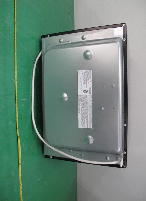
C5F7NF1CMO900N
Nov 23, 2014Microwave Oven
Equipment Class
8CC - Part 18 Consumer Device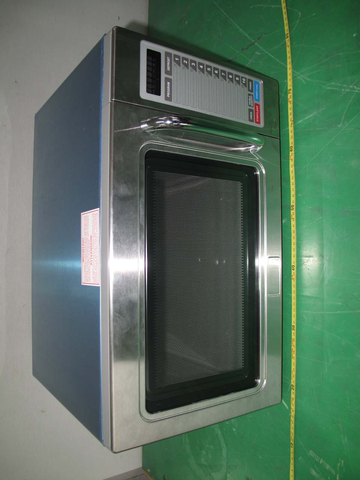
C5F7NF9PMO100N
Mar 25, 2013Commercial Microwave Oven
Equipment Class
8CC - Part 18 Consumer Device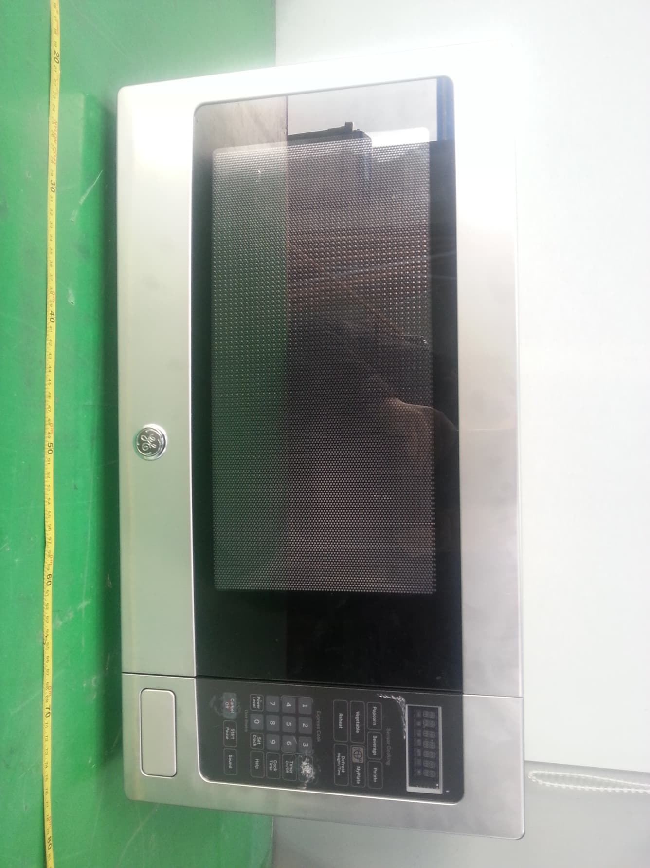
C5F7NF22MO110N
Jan 23, 2013Microwave Oven
Equipment Class
8CC - Part 18 Consumer Device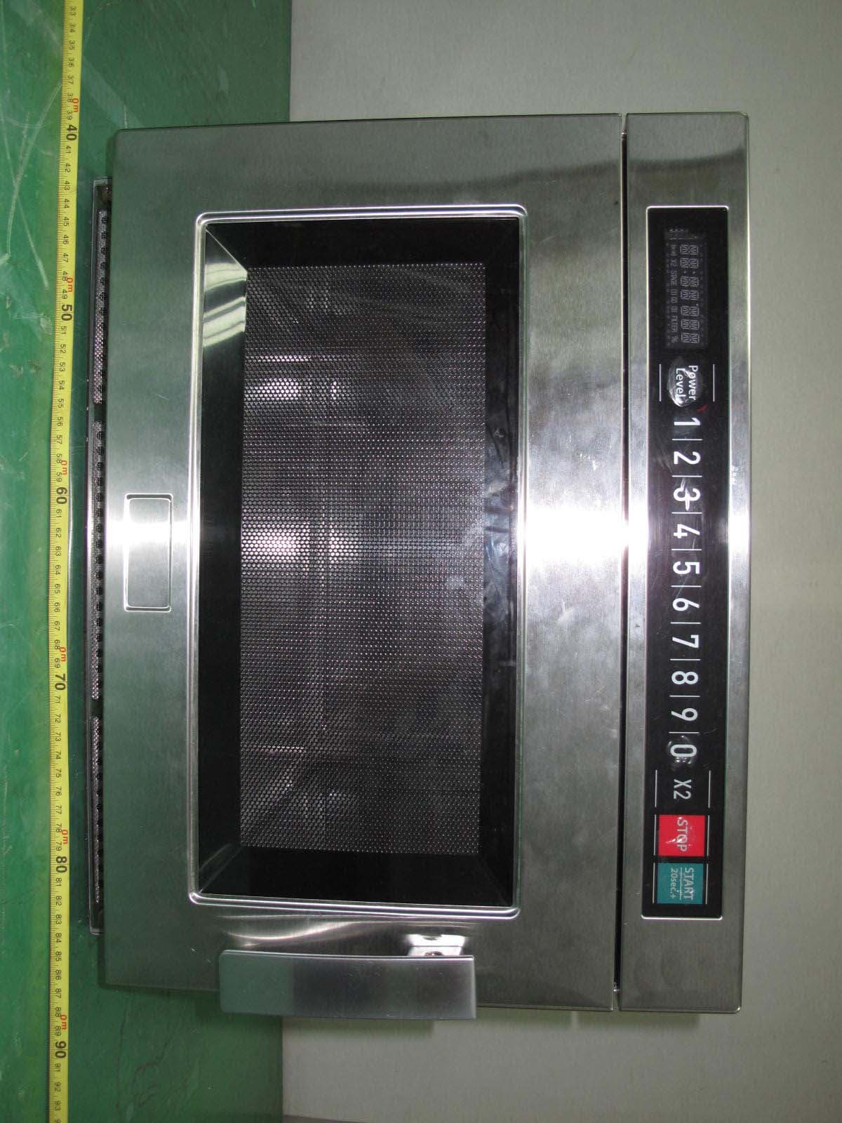
C5F7NF9FMO180N
Sep 05, 2011Commercial Microwave Oven
Equipment Class
8CC - Part 18 Consumer Device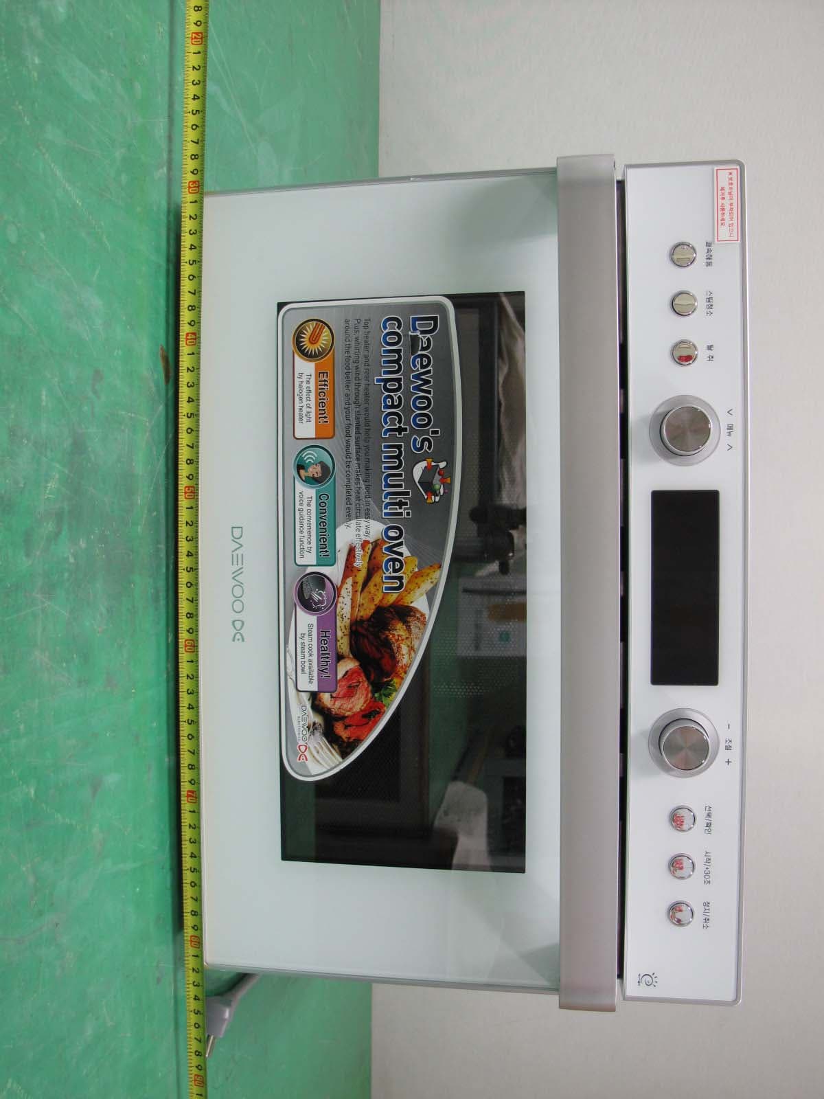
C5F7NF1CMO800N
Dec 16, 2010Microwave Oven
Equipment Class
8CC - Part 18 Consumer Device