C5F7NF0016DVDRW COMBO Recorder
WINIA Electronics Co., Ltd.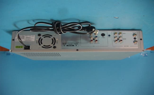
Click to zoom
Application Details
- Equipment Class
- HID - Part 15 TV Interface Device
- Date of Grant
- Mar 28, 2005
- Application Purpose
- Original Equipment
- Date of Application
- Mar 28, 2005
- Equipment Note
- DVDRW COMBO Recorder
- Frequency Range
- 67.25000000 - 71.75000000
- Company
- WINIA Electronics Co., Ltd.
- Country
- South Korea
Documents & Files
Document Text
Text extracted from the exhibit documents filed with the FCC. Open a document above to read the original.
Users Manual
DVD Recorder + VCR DVD Recorder + VCR DF-Q74D2N-JS User Manual P/N : 97P95600N0-** i Important Safeguards Important Safeguards CAUTION: TO REDUCE THE RISK OF ELECTRIC SHOCK, DO NOT REMOVE COVER (OR BACK). NO USER-SERVICEABLE PARTS INSIDE. REFER SERVICING TO QUALIFIED SERVICE PERSONNEL. The lightning flash with arrowhead symbol, within an equilateral triangle, is intended to alert the user to the presence of uninsulated ‘dangerous voltage‘ within the product’s enclosure that may be of sufficient magnitude to constitute a risk of electric shock. The exclamation point within an equilateral triangle is intended to alert the user to the presence of important operating and servicing instructions in the literature accompanying the appliance. CAUTION RISK OF ELECTRIC SHOCK DO NOT OPEN WARNINGTO REDUCE THE RISK OF FIRE OR ELECTRIC SHOCK, DO NOT EXPOSE THIS APPLIANCE TO RAIN OR MOISTURE. CAUTIONTO PREVENT ELECTRIC SHOCK, MATCH WIDE BLADE OF PLUG TO WIDE SLOT, FULLY INSERT. ATTENTIONPOUR ÉVITER LES CHOC ÉLECTRIQUES, INTRODUIRE LA LAME LA PLUS LARGE DE LA FICHE DANS LA BORNE CORRESPONDANTE DE LA PRISE ET POUSSER JUSQU’AU FOND. WARNING: Do not install this equipment in a confined space such as a bookcase or similar unit. NOTE TO CABLE/TV INSTALLER: This reminder is provided to call the cable TV system installer’s attention to Article 820-40 of the National Electric Code (U.S.A.). The code provides guidelines for proper grounding and, in particular, specifies that the cable ground shall be connected to the grounding system of the building, as close to the point of the cable entry as practical. CAUTION: This DVD Recorder+VCR employs a Laser System. To ensure proper use of this product, please read this owner’s manual carefully and retain for future reference. Should the DVD Recorder+VCR require maintenance, contact an authorized service center. Use of controls, adjustments, or the performance of procedures other than those specified herein may result in hazardous radiation exposure. To prevent direct exposure to laser beam, do not try to open the enclosure. Visible laser radiation when open. DO NOT STARE INTO BEAM. CAUTION: The apparatus should not be exposed to water (dripping or splashing) and no objects filled with liquids, such as vases, should be placed on the apparatus. FCC WARNING: This equipment may generate or use radio frequency energy. Changes or modifications to this equipment may cause harmful interference unless the modifications are expressly approved in the instruction manual. The user could lose the authority to operate this equipment if an unauthorized change or modification is made. CLASS 1 LASER PRODUCT KLASSE 1LASER PRODUKT LUOKAN 1LASER LAITE KLASS 1LASER APPARAT CLASSE 1PRODUIT LASER INTRODUCTION ii CAUTION: PLEASE READ AND OBSERVE ALL WARNINGS AND INSTRUCTIONS IN THIS OWNER’S MANUAL AND THOSE MARKED ON THE PRODUCT. RETAIN THIS MANUAL FOR FUTURE REFERENCE. This product has been designed and manufactured to assure personal safety. Improper use can result in electric shock or fire hazard. The safeguards incorporated in this product will protect you if you observe the following procedures for installation, use, and servicing. This product does not contain any parts that can be repaired by the user. DO NOT REMOVE THE CABINET COVER, OR YOU MAY BE EXPOSED TO DANGEROUS VOLTAGE. REFER SERVICING TO QUALIFIED SERVICE PERSONNEL ONLY. IMPORTANT SAFETY INSTRUCTIONS REGULATORY INFORMATION: FCC Part 15 This product has been tested and found to comply with the limits for a Class B digital device, pursuant to Part 15 of the FCC Rules. These limits are designed to provide reasonable protection against harmful interference when the product is operated in a residential installation. This product generates, uses, and can radiate radio frequency energy and, if not installed and used in accordance with the instruction manual, may cause harmful interference to radio communications. However, there is no guarantee that interference will not occur in a particular installation. If this product does cause harmful interference to radio or television reception, which can be determined by turning the product off and on, the user is encouraged to try to correct the interference by one or more of the following measures: - Reorient or relocate the receiving antenna. - Increase the separation between the product and receiver. - Connect the product into an outlet on a circuit different from that to which the receiver is connected. - Consult the dealer or an experienced radio/TV technician for help. FCC COMPLIANCE: The responsible party for this product’s compliance is: GoVideo, 7835 East McClain Drive, Scottsdale, AZ 85260, USA. SERIAL NUMBER: The serial number is found on the back of the DVD Recorder+VCR. This number is for this unit only. You should record requested information here and retain this guide as a permanent record of your purchase. Model No. ___________________________________ Serial No. ___________________________________ 1Read these instructions. All these safety and operating instructions should be read before the product is operated. 2Keep these instructions. The safety, operating and use instructions should be retained for future reference. 3Heed all warnings. All warnings on the product and in the operating instructions should be adhered to. 4Follow all instructions. All operating and use instructions should be followed. Important Safeguards iii 5Do not use this product near water. For example: near a bath tub, wash bowl, kitchen sink, laundry tub, in a wet basement; or near a swimming pool; and other areas located near water. 6Clean only with dry cloth. Unplug this product from the wall outlet before cleaning. Do not use liquid cleaners. 7Do not block any ventilation openings. Install in accordance with the manufacturer’s instructions. Slots and openings in the cabinet are provided for ventilation and to ensure reliable operation of the product and to protect it from overheating. The openings sh…
Text truncated - open the document above for the full version.
Block Diagram
55 44 33 22 11 D D C C B B A A MICOM IC601 SULLPYTAKEREC TUNER A/V Hi-Fi IC301 LA72607 IC101 S501 UPSAFETY REEL REEL S502SW601 RF101 IC LA71207 IC IC251 LA73054 IC302 SWITCHING IC CAM SW SW501 C/SS-CLOCKS-INS-OUT IIC_CLK IIC_DATAIIC_CLK IIC_DATA IIC_DATA NORMAL_AUDIO IIC_CLKNORMAL_AUDIO IN OUT RF_VIDEOLINE1_VIDEO(FROM_JACK_701)FOR_REC_VIDEO(FORM_DVD_PART)LINE2_VIDEO(FROM_JACK_101) VIDEO_IN VIDEO_IN LINE1_AUDIO(FROM_JACK_701)FOR_REC_AUDIO(FORM_DVD_PART)LINE2_AUDIO(FROM_JACK_101) SIF MTS AUDIO_IN CVBS COMPONENT S_VIDEO PSCAN_DATA FOR_REC_VIDEO COMPOSIT COMPONENT S_VIDEO JK101 JK102 JK105TUNER CVBS ICD02OP_AMP_IC AUDIO_OUT FOR_REC_AUDIO JK101JK102TUNER AUDIO SPDIF JK102JK104 IIC_DATA IIC_CLK AFT TV/VCR TO_TUNER DATA FSC(3.58MHz) 4FSC(14.32MHz) DVD_PART BLOCK_DIAGRAM VCR_PART_BLOCK_DIAGRAM FSC(3.58MHz) DF-Q74D2N-JS DAEWOO ELECTRONICS Digital Video Lab. 3 Team H.Y.KIM Y.LEE Y.LEE VCR PART BLOCK DIAGRAM DRAWN DESIGNED CHECKED APPROVED MODEL FILE NAMEDATEREVISED REV NO. SHEET / 55 44 33 22 11 D D C C B B A A MPEG2 CS4344 ADR/CTL AUDIO DAC DATA RESET DDRAM(256M BIT) DV 1394 INPUTCVBS IN FROM ANALOG BOARD FLASH 16M BIT CODEC ADR/CTL MT8105 TSB41AB1 DATA OPTION AUDIO ADCCS5340 AUDIO R IN FORM ANALOG BOARD REMOCONRECEIVER ARSDATARCLKARLRCKARBCK ASDAT0ABCKALRCKACLK AUDIO R OUT TO ANALOG BOARDAUDIO L OUT TO ANALOG BOARD AUDIO L IN FORM ANALOG BOARD CVBS OUT TO ANALOG BOARDCOMPONENT OUT TO ANALOG BOARDS-VIDEO OUT TO ANALOG BOARD SPDIF OUT TO ANALOG BOARD MT1818 IDE INTERFACE SDRAM ADR/CTLDATA ADR/CTL DATA FLASH 8M BIT MT1816 16M BIT WIDSCLKSDATA PICK-UPHEAD PUH SledSpindleTray LVDS & OPU DVD_PART_BLOCK_D IAGRAM < MODEL NAME > <REV NO.> DAEWOO ELECTRONICS Digital Media Lab. <FILE NAME> 1 Team <REVISED> <CHECKED> <APPROVED> <DRAWN> <DESIGNED> 01 : Figaro_2 COVER PAGE 19 Monday, February 28, 2005 DRAWN DESIGNED CHECKED APPROVED MODEL FILE NAMEDATEREVISED REV NO. SHEET /
Cover Letter(s)
1 Helen Zhao Subject:FW: Daewoo Electronics Corporation, FCC ID: C5F7NF0016, Assessment NO.: AN05T4659, Notice#1 From: sgkim Sent: Tuesday, March 29, 2005 1:27 AM To: Helen Zhao Subject: RE: Daewoo Electronics Corporation, FCC ID: C5F7NF0016, Assessment NO.: AN05T4659, Notice#1 Dear Helen, For the project of AN05T4659 (Daewoo Elec.) Answer #1: Modified test report was uploaded to your web. The plots were re-scaned and modified. Answer #2: We were missing to mark the calibration date. It was modified and uploaded. Answer #3: According to your comments, we retest for "Transfer Switch Isolation Measurement" and modified it. Best regards, S.G.Kim -----Original Message----- From: Helen Zhao Sent: Thursday, March 24, 2005 7:05 AM Subject: Daewoo Electronics Corporation, FCC ID: C5F7NF0016, Assessment NO.: AN05T4659, Notice#1 Question #1: I received the revised test report of AN05T4659. Unfortunately I found they are still not clear enough. For your quick reference, here I attach the test plots extracted from your test report of AN05T4573. You can find the plots from your previous report are much clear. Please understand that FCC request all traces on the plots must be readable clearly, FCC might request resubmission of the documents when they do audit, we experienced the problem, I am OK to issue the grant now, but if you can, please kindly revise the test report again. Quetsion #2: There are no calibration dates on the test report part 2 of 2, instead it only stated that "The test equipment used is calibrated in regular for every year." Unfortunately, it does not comply with ANSI C63.4 report format, please add calibration date for each equipment on the report (Page 4, 19, 27). Question #3: The plots of "Transfer Switch Isolation Measurement" on report part 2 of 2 show the levels are all very close to the limit (9.53 dBuV), not around 5.3-5.9 dBuV as the indicated in the table. please explain. Thank you, Helen
External Photos
IST Co., Ltd. EMC LABORATORY External Photos.Ref.No : 05-IST-0142 1 of 2 The DUT photos Front View Rear View IST Co., Ltd. EMC LABORATORY External Photos.Ref.No : 05-IST-0142 2 of 2 The DUT photos Side View Side View
ID Label/Location Info
IST Co., Ltd. EMC LABORATORY Label Location.Ref.No : 05-IST-0142 1 of 1 Label Sample Label Location
Internal Photos
IST Co., Ltd. EMC LABORATORY Internal Photos. Ref.No: 05-IST-0142 1 of 13 The DUT photos Inner Top View Inner Top View IST Co., Ltd. EMC LABORATORY Internal Photos. Ref.No: 05-IST-0142 2 of 13 The DUT photos VCR Deck Top View VCR Deck Bottom View IST Co., Ltd. EMC LABORATORY Internal Photos. Ref.No: 05-IST-0142 3 of 13 The DUT photos Main Board PCB Parts View Main Board PCB Copper View IST Co., Ltd. EMC LABORATORY Internal Photos. Ref.No: 05-IST-0142 4 of 13 The DUT photos DVD Deck Top View DVD Deck Bottom View IST Co., Ltd. EMC LABORATORY Internal Photos. Ref.No: 05-IST-0142 5 of 13 The DUT photos Power Board PCB Parts View Power Board PCB Copper View IST Co., Ltd. EMC LABORATORY Internal Photos. Ref.No: 05-IST-0142 6 of 13 The DUT photos AUX front Input Panel PCB Parts View AUX front Input Panel PCB Copper View IST Co., Ltd. EMC LABORATORY Internal Photos. Ref.No: 05-IST-0142 7 of 13 The DUT photos Top Cover IST Co., Ltd. EMC LABORATORY Internal Photos. Ref.No: 05-IST-0142 8 of 13 Tuner photos(TCMN0682PA20B4) Front View Rear View IST Co., Ltd. EMC LABORATORY Internal Photos. Ref.No: 05-IST-0142 9 of 13 Tuner photos(TCMN0682PA20B4) Inner Front View Inner Rear View IST Co., Ltd. EMC LABORATORY Internal Photos. Ref.No: 05-IST-0142 10 of 13 Tuner photos(TADM-H201F) Front View Rear View IST Co., Ltd. EMC LABORATORY Internal Photos. Ref.No: 05-IST-0142 11 of 13 Tuner photos(TADM-H201F) Inner Front View Inner Rear View IST Co., Ltd. EMC LABORATORY Internal Photos. Ref.No: 05-IST-0142 12 of 13 Tuner photos(TMZH2-030A) Front View Rear View IST Co., Ltd. EMC LABORATORY Internal Photos. Ref.No: 05-IST-0142 13 of 13 Tuner photos(TMZH2-030A) Inner Front View Inner Rear View
Test Report
IST Co., Ltd. EMC LABORATORY TEST REPORT NO. : 05-IST-0142 1 of 67 Certification of Compliance CFR 47 Part 15 Subpart B Test Report File No. 05-IST-0142 Date of Issue March 29,2005 Model(s) DF-Q74D2N-JS DAEWOO Basic Model DVR-S06 DAEWOO Buyer Model RV5000 CINE Buyer Model VR2946 GOVIDEO Buyer Model VR1950 GOVIDEO Buyer Model VR1955 GOVIDEO Buyer Model Kind of Product DVDRW COMBO Recorder Applicant Daewoo Electronics Corporation. 543, Dangjung-Dong, Kunpo-City, Kyounggi-DO, Korea Manufacturer Daewoo Electronics Corporation. 295, Gondan-dong, Kumi-city, Kyungsangbuk-do, Korea. Test Result Positive Negative Reviewed By Approved By S.J.Cho / EMC Group Manager J.H.LEE / Chief - Investigations requested : Measurement to the relevant clauses of F.C.C rules and regulations Part 15 Subpart B – Unintentional Radiatiors - The test report with appendix consists of 67 pages. - The test result only responds to the tested sample. - It is not allowed to copy this report even partly without the allowance of IST EMC Laboratory. - This equipment as for has been shown to be capable of continued compliance with the applicable technical standards as indicated in the measurement report and was tested in accordance with the measurement procedures specified in ANSI C63.4 2003. IST Co., Ltd. EMC LABORATORY TEST REPORT NO. : 05-IST-0142 2 of 67 TABLE OF CONTENTS Table of contents 2 Information of test laboratory, Environmental condition, Power used 3 Descriptions of test 4-6 Conducted Emission 4 Radiated Emission 5 Output Signal level measurements 6 Output Terminal Conducted Spurious Emission 6 Transfer Switch Isolation Measurement 6 Summary 7 Test Conditions and Data - Emission Conducted Emission 0.15MHz - 30MHz Test equipment / Data and Plots 8-32 Radiated Emission 30MHz - 1GHz Test equipment / Data and Plots 33-36 Output Signal level measurements Test equipment / Data and Plots 37-51 Output Terminal Conducted Spurious Emission 30MHz - 1GHz Test equipment / Data and Plots 52-59 Transfer Switch Isolation Measurement 30MHz - 1GHz Test equipment / Data and Plots 60-67 Information OF TUNERS Manufacture Manufacture Name SAMSUNG Electric Co., Ltd. TCMN0682PA20B4 LG Innotek Co., Ltd. TADM-H201F Korea ALPS TMZH2-030A IST Co., Ltd. EMC LABORATORY TEST REPORT NO. : 05-IST-0142 3 of 67 INFORMATIONS OF TEST LABORATORY EMC LABORATORY of IST Co., Ltd.(FCC Filing Lab) San 21-8, Goan-Ri, Baekam-Myun, Yongin-City Kyonggi-Do, 449-860, Korea TEL : +82 31 333 4093 FAX : +82 31 333 4094 ENVIRONMENTAL CONDITIONS Temperature 14 Humidity 48 % Atmospheric pressure 1002 mbar POWER SUPPLY SYSTEM USED Power supply system 120Vac , 60Hz PRODUCT INFORMATIONS Power supply system 120Vac , 60Hz Power consumption Maximum:25W (Power-OFF:3.4W) Signal type NTSC COLOR Antenna Input Antenna or CATV input, 75 Recordable discs DVD+R, DVD+RW, DVD-R, DVD-RW Video recording format Sampling frequency : 27MHz Compression format : MPEG 2 Audio recording format Sampling frequency : 48KHz Compression format : MPEG 1 Layer 2 VCR Head system 4 Head Video, 2 Head Hi-Fi helical scan azimuth system Timer 12-hour display type with AM,PM Antenna : 75 (VHF/UHF) VHF output signal : Channel 3 or 4(Switchable) - EMC suppression device is not used during the test. - Please refer to user’s manual. IST Co., Ltd. EMC LABORATORY TEST REPORT NO. : 05-IST-0142 4 of 67 DESCRIPTIONS OF TEST Conducted Emissions: The measurement were performed over the frequency range of 0.45MHz to 30MHz using a 50/50uH LISN as the input transducer to a Spectrum Analyzer or a Field Intensity Meter. The measurements were made with the detector set for "Peak" amplitude within an bandwidth of 10KHz or for "quasi-peak" within a bandwidth of 9KHz. - Procedure of Test The line-conducted facility is located inside a shielded room No.1. A 1m X 1.5m wooden table 80cm height is placed 40cm away from the vertical wall and 1.5m away from the other wall of the shielded room. The R/S ESH3-Z5 and EMCO 3825/2 LISN are bonded to bottom of the shielded room. The EUT is located on the wooden table with distance more than 80cm from the LISN and powered from the EMCO LISN .The peripheral equipment is powered from the other LISN. Power to the LISNs are filtered by a noise cut power line filters. All electrical cables are shielded by braided tinned steel tubing with inner ? 1.2cm. If the EUT is a DC-powered device, power will be derived from the source power supply it normally will be powered from and this supply lines will be connected to the EMCO LISN. All interconnecting cables more than 1m were shortened by non-inductive bundling to a 1m length. Sufficient time for the EUT, support equipment, and test equipment was allowed in order for them to warm up to their normal operating conditions. The RF output of the LISN was connected to the R/S receiver to determine the frequency producing the maximum emission from the EUT. The frequency producing the maximum level was reexamined using Quasi-Peak mode by manual measurement, after scanned by automatic Peak mode for frequency range from 0.45 to 30MHz. The bandwidth of the receiver was set to 10kHz. The EUT, peripheral equipment, and interconnecting cables were arranged and manipulated to maximize each EME emission. 215 >150>40 80 Receiver EUT LISN 80 ? 80 80 40 ? 80 Measuring apparatus Mains Filter Mains Rear side Equipment under test Coaxial cable Artificial mains network Screened room Non-metallic support 80 < Side View > < Concept Drawing > IST Co., Ltd. EMC LABORATORY TEST REPORT NO. : 05-IST-0142 5 of 67 DESCRIPTION OF TEST Radiated Emissions: The measurement was performed over the frequency range of 30MHz to 1GHz using antenna as the input transducer to a Spectrum analyzer or a Field Intensity Meter. The measurement was made with the detector set for "quasi-peak" within a bandwidth of 120KHz. - Procedure of Test Preliminary measurements were made at 3 meter using bi-conical and log-periodic antennas, and spectrum analyzer to determine the frequency producing the max. em…
Text truncated - open the document above for the full version.
Test Report
IST Co., Ltd. EMC LABORATORY TEST REPORT NO. : 05-IST-0142 33 of 67 TEST CONDITIONS AND DATA Radiated Emissions [Applicable] Test Equipment Used The test equipment used is calibrated in regular for every year. Model Name Manufacturer Descriptions Calibration Date Serial Number ESVP Rohde & Schwarz Test Receiver Jul. 15, 2004 861744/004 VULB 9160 Schwarzbeck Antenna Jul. 19, 2004 3048 PM5418 FLUKE Pattern Generator May. 10, 2004 LO 796009 Auxiliary Equipment Used Model Name Manufacturer Descriptions 14C5NT Daewoo Electronics. Color TV Receiver Accessories including cables Name Length Port and Descriptions RCA 1.5m Video / Audio S-Video - Environmental Conditions Temperature 14 Humidity 48 Atmosphere pressure 1002mbar Test Program RF Receiving during VCR REC RF Receiving during DVD REC VCR Playback during DVD REC DVD Playback during VCR REC Test Area Open Area Test Site #2 Test Date March 08, 2005 Note : IST Co., Ltd. EMC LABORATORY TEST REPORT NO. : 05-IST-0142 34 of 67 Radiated Emissions (Disturbance Radiation) [Applicable] Tuner : TCMN0682PA20B4 (Samsung) System Freq. (MHz) Pol. (H/V) Limits (dBuV/m) Result (dBuV/m) Margin (dB) RF Receiving during DVD record 71.62 V 40.0 22.6 17.4 76.95 V 40.0 22.0 18.0 216.01 H 46.0 41.8 4.2 230.45 H 46.0 30.2 15.8 297.00 H 46.0 38.1 7.9 328.78 H 46.0 33.8 12.2 343.64 H 46.0 40.8 5.2 445.50 H 46.0 38.3 7.7 474.17 H 46.0 36.8 9.2 593.04 H 46.0 36.5 9.5 RF Receiving during VCR record 216.01 H 46.0 36.2 9.8 297.00 H 46.0 36.5 9.5 343.60 H 46.0 39.8 6.2 445.50 H 46.0 35.6 10.4 593.00 H 46.0 34.3 11.7 DVD Playback during VCR record 45.30 V 40.0 22.0 18.0 216.01 H 46.0 35.2 10.8 328.70 H 46.0 36.3 9.7 445.50 H 46.0 37.6 8.4 593.02 V 46.0 34.5 11.5 VCR Playback during DVD record 76.95 V 40.0 21.0 19.0 216.01 H 46.0 41.8 4.2 230.50 H 46.0 29.9 16.1 297.01 H 46.0 37.7 8.3 328.80 H 46.0 33.7 12.3 343.64 H 46.0 38.5 7.5 445.50 H 46.0 37.7 8.3 465.00 H 46.0 36.8 9.2 593.01 H 46.0 36.9 9.1 End of data Note : IST Co., Ltd. EMC LABORATORY TEST REPORT NO. : 05-IST-0142 35 of 67 Radiated Emissions (Disturbance Radiation) [Applicable] Tuner : TADM-H201F (LG) System Freq. (MHz) Pol. (H/V) Limits (dBuV/m) Result (dBuV/m) Margin (dB) RF Receiving during DVD record 76.95 V 40.0 22.3 17.7 216.01 V 46.0 38.6 7.4 298.06 H 46.0 37.3 8.7 343.62 V 46.0 37.0 9.0 445.53 V 46.0 36.3 9.7 593.98 V 46.0 37.6 8.4 RF Receiving during VCR record 216.00 H 46.0 39.9 6.1 298.05 H 46.0 29.7 16.3 594.00 V 46.0 42.4 3.6 DVD Playback during VCR record 216.00 H 46.0 40.9 5.1 298.05 H 46.0 30.2 15.8 328.13 H 46.0 33.2 12.8 445.50 H 46.0 37.3 8.7 593.97 V 46.0 42.7 3.3 VCR Playback during DVD record 76.90 V 40.0 22.6 17.4 216.01 H 46.0 38.7 7.3 298.00 H 46.0 37.0 9.0 343.60 V 46.0 37.3 8.7 445.46 V 46.0 35.4 10.6 593.76 V 46.0 41.0 5.0 End of data Note : IST Co., Ltd. EMC LABORATORY TEST REPORT NO. : 05-IST-0142 36 of 67 Radiated Emissions (Disturbance Radiation) [Applicable] Tuner : TMZH2-030A (ALPS) System Freq. (MHz) Pol. (H/V) Limits (dBuV/m) Result (dBuV/m) Margin (dB) RF Receiving during DVD record 216.01 V 46.0 33.3 12.7 297.06 H 46.0 39.1 6.9 321.31 H 46.0 38.6 7.4 343.62 H 46.0 36.2 9.8 445.49 H 46.0 39.6 6.4 449.57 H 46.0 38.3 7.7 524.99 H 46.0 35.6 10.4 533.45 V 46.0 36.4 9.6 594.00 V 46.0 40.6 5.4 RF Receiving during VCR record 216.01 V 46.0 36.4 9.6 297.04 H 46.0 38.7 7.3 321.30 H 46.0 39.1 6.9 343.59 H 46.0 36.0 10.0 445.42 H 46.0 39.3 6.7 449.60 H 46.0 37.6 8.4 524.97 H 46.0 37.8 8.2 533.42 V 46.0 38.2 7.8 594.00 V 46.0 41.4 4.6 DVD Playback during VCR record 216.01 V 46.0 35.9 10.1 297.01 H 46.0 38.0 8.0 321.63 H 46.0 37.8 8.2 343.45 H 46.0 35.5 10.5 445.16 H 46.0 38.7 7.3 449.76 H 46.0 38.0 8.0 524.90 H 46.0 37.6 8.4 533.46 V 46.0 37.4 8.6 594.00 V 46.0 42.2 3.8 VCR Playback during DVD record 216.01 V 46.0 33.4 12.6 297.00 H 46.0 37.3 8.7 321.33 H 46.0 38.4 7.6 343.72 H 46.0 35.9 10.1 445.44 H 46.0 37.9 8.1 449.63 H 46.0 38.1 7.9 524.99 V 46.0 35.3 10.7 533.42 H 46.0 35.9 10.1 594.00 V 46.0 39.1 6.9 End of data Note : IST Co., Ltd. EMC LABORATORY TEST REPORT NO. : 05-IST-0142 37 of 67 TEST CONDITIONS AND DATA Output Signal Level Measurements [Applicable] Test Equipment Used The test equipment used is calibrated in regular for every year. Model Name Manufacturer Descriptions Calibration Date Serial Number 8566B Hewlett Packard Spectrum Analyzer Dec. 01, 2004 3014A07159 85685A Hewlett Packard RF preselector Dec. 01, 2004 2817A00760 RAM Rohde & Schwarz 50/75ohms matching pad - 836625/033 PM5418 FLUKE Pattern Generator May. 10, 2004 LO 796009 Auxiliary Equipment Used Model Name Manufacturer Descriptions 14C5NT Daewoo Electronics. Color TV Receiver Accessories including cables Name Length Port and Descriptions RCA 1.5m Video / Audio Environmental Conditions Temperature 15 Humidity 48 Atmosphere pressure 1002mbar Test Program Playback and Record mode Test Area Compact Chamber Test Date March 07, 2005 Note : Limit Calculations For Video Signal 346.4 X 75 1/2 = 2999uV = 69.54dBuV = -37.46 dBm For Audio Signal 77.5 X 75 1/2 = 671.17uV = 56.53dBuV = -50.46 dBm The test were performed with RF receiving as VITS. The VITS signals, 1V and 5V peak-to-peak, were used for channel 3 and channel 4 with alternate. The above test program were employed for each channel. IST Co., Ltd. EMC LABORATORY TEST REPORT NO. : 05-IST-0142 38 of 67 Output Signal Level Measurements TV CH. Freq.(MHz) Level(dBuV) Limit(dBuV) Mode Margin(dB) 3(Pix) 61.29 57.60 69.54 Playback 11.94 3(Aud) 65.81 42.00 56.53 Playback 14.53 3(Pix) 61.29 57.60 69.54 Record 11.94 3(Aud) 65.83 41.90 56.53 Record 14.63 4(Pix) 67.28 57.20 69.54 Playback 12.34 4(Aud) 62.75 41.40 56.53 Playback 15.13 4(Pix) 67.28 57.20 69.54 Record 12.34 4(Aud) 62.76 41.50 56.53 Record 15.03 Output Signal Tabulated Data with Tuner (Samsung Model: TCMN0682PA20B4) TV CH. Freq.(MHz) Level(dBuV) Limit(dBuV) Mode Margin(dB) 3(Pix) 61.29 58.10 69.54 Playback 11.44 3(Aud) 65.82 42.30 56.53 Playback 14.23 3(Pix) 61.29 58.20 69.54 Record 11.34 3(Aud) 65.81 42.30 56.53 Rec…
Text truncated - open the document above for the full version.
Test Setup Photos
IST Co., Ltd. EMC LABORATORY Test Setup Photos. Ref. No: 05-IST-0142 1 of 2 Test Setup Photos – Radiated Emissions Front View Rear View IST Co., Ltd. EMC LABORATORY Test Setup Photos. Ref. No: 05-IST-0142 2 of 2 Test Setup Photos – Conducted Emissions Front View Rear View
Contact Information
Applicant
Youjin Choi(Manager)
Test Firm
IST Co., LtdBong Kyoon Bae
Technical Specifications
| # | Rule Parts | Frequency Range | Power Output |
|---|---|---|---|
| 2 | 15B | 67.25 MHz - 71.75 MHz | - |
Other Applications from WINIA Electronics Co., Ltd.
C5F7NF1CMO900N
Nov 23, 2014Microwave Oven
Equipment Class
8CC - Part 18 Consumer Device
C5F7NF9PMO100N
Mar 25, 2013Commercial Microwave Oven
Equipment Class
8CC - Part 18 Consumer Device
C5F7NF22MO110N
Jan 23, 2013Microwave Oven
Equipment Class
8CC - Part 18 Consumer Device
C5F7NF9FMO120N
May 06, 2012Commercial Microwave Oven
Equipment Class
8CC - Part 18 Consumer Device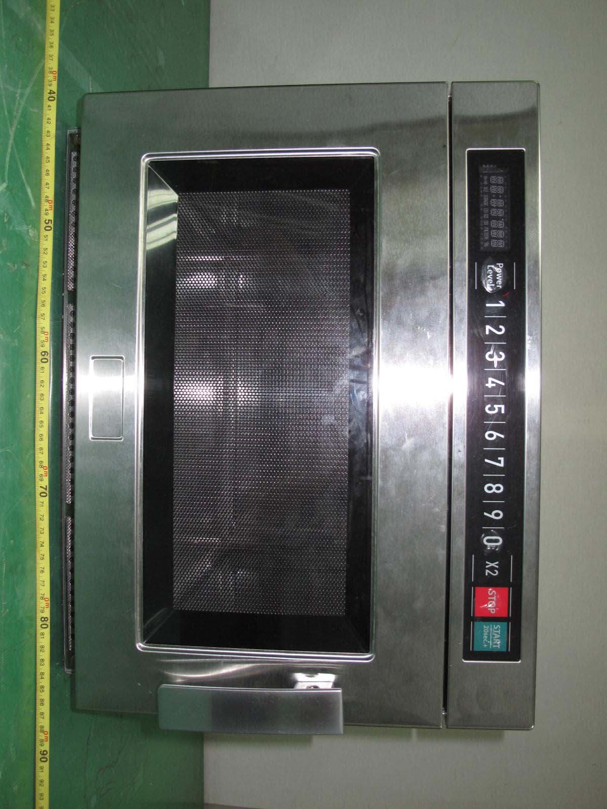
C5F7NF9FMO180N
Sep 05, 2011Commercial Microwave Oven
Equipment Class
8CC - Part 18 Consumer Device