C5F7NF6LMO600NMICROWAVE OVEN
WINIA Electronics Co., Ltd.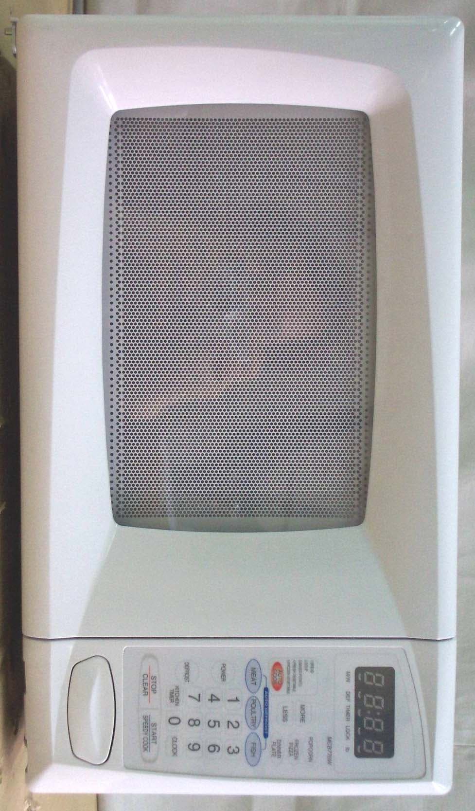
Click to zoom
Application Details
- Equipment Class
- 8CC - Part 18 Consumer Device
- Date of Grant
- May 09, 2006
- Application Purpose
- Original Equipment
- Date of Application
- May 09, 2006
- Equipment Note
- MICROWAVE OVEN
- Frequency Range
- 2450.00000000 - 2450.00000000
- Company
- WINIA Electronics Co., Ltd.
- Country
- South Korea
Documents & Files
Document Text
Text extracted from the exhibit documents filed with the FCC. Open a document above to read the original.
Users Manual
Before operating this oven, please read these instructions completely. OPERATING INSTRUCTIONS & COOK BOOK MICROWAVE OVEN KOR-6L0B 1 PRECAUTIONS TO AVOID POSSIBLE EXPOSURE TO EXCESSIVE MICROWAVE ENERGY (a) Do not attempt to operate this oven with the door opensince open-door operation can result in harmful exposure to microwave energy. It is important not to defeat or tamper with the safety interlocks. (b) Do not place any objectbetween the oven front face and the door or allow soil or cleaner residue to accumulate on sealing surfaces. (c) Do not operate the oven if it is damaged.It is particularly important that the oven door close properly and that there is no damage to the: (1) door (bent), (2) hinges and latches (broken or loosened), (3) door seals and sealing surfaces. (d) The oven should not be adjusted or repaired by anyone except properly qualified service personnel. TABLE OF CONTENTS • PRECAUTIONS TO AVOID POSSIBLE EXPOSURE TO EXCESSIVE MICROWAVE ENERGY.................................1 • IMPORTANT SAFETY INSTRUCTIONS ..........................................................................................................................2 • FEDERAL COMMUNICATIONS COMMISSION RADIO FREQUENCY INTERFERENCE STATEMENT .........................................................................................3 • GROUNDING INSTRUCTIONS ........................................................................................................................................3 • INSTALLATION ...................................................................................................................................................................4 • SPECIFICATIONS ..............................................................................................................................................................5 • FEATURES DIAGRAM.......................................................................................................................................................6 • FEATURES DIAGRAM (CONTINUED) ............................................................................................................................7 • OPERATION PROCEDURE ..............................................................................................................................................8 • CONTROLS.........................................................................................................................................................................9 SETTING THE CLOCK......................................................................................................................................9 WEIGHT DEFROSTING..................................................................................................................................10 TIME DEFROSTING........................................................................................................................................10 COOKING IN ONE STAGE .............................................................................................................................11 COOKING IN TWO STAGES ..........................................................................................................................11 +30SEC ...........................................................................................................................................................12 AUTO COOK ...................................................................................................................................................12 CHILD SAFETY LOCK ....................................................................................................................................13 TO SET POWER SAVE MODE.......................................................................................................................13 TO STOP THE OVEN WHILE THE OVEN IS OPERATING ...........................................................................13 • CARE OF YOUR MICROWAVE OVEN..........................................................................................................................14 • BEFORE YOU CALL FOR SERVICE .............................................................................................................................15 • CARE AND CLEANING....................................................................................................................................................15 • QUESTIONS AND ANSWERS........................................................................................................................................16 • COOKING INSTRUCTIONS ............................................................................................................................................17 • USE YOUR MICROWAVE OVEN SAFELY ...................................................................................................................18 • ARCING .............................................................................................................................................................................18 • MICROWAVING PRINCIPLES ........................................................................................................................................19 • HOW MICROWAVES COOK FOOD .....................................................................................................................19 • CONVERSION CHARTS ........................................................................................................................................19 • COOKING TECHNIQUES................................................................................................................................................20 • DEFROSTING GUIDE......................................................................................................................................................21 • COOKING & REHEATING…
Text truncated - open the document above for the full version.
Block Diagram
Input 120Vac 60Hz Note: Components outlined with dotted line is optional and may not be employed in the model H.V. TransformerH.V. Capacitor Oven Cavity BLOCK DIAGRAM FCC ID: C5F7NF6LMO600N Magnetron LampFan Motor Turntable Motor Heating Element Control Panel (Clock frequency 4MHz) H.V.Diode
External Photos
Test Report No.: NK2GE331 FCC Certification Daewoo Electronics Corporation FCC ID:C5F7NF6LMO600N Page 29 of 37 APPENDIX C – EUT PHOTOGRAPHS z Front View of EUT Test Report No.: NK2GE331 FCC Certification Daewoo Electronics Corporation FCC ID:C5F7NF6LMO600N Page 30 of 37 z Rear View of EUT Test Report No.: NK2GE331 FCC Certification Daewoo Electronics Corporation FCC ID:C5F7NF6LMO600N Page 31 of 37 z Door Open View of EUT
ID Label/Location Info
Test Report No.: NK2GE331 FCC Certification Daewoo Electronics Corporation FCC ID:C5F7NF6LMO600N Page 24 of 37 APPENDIX A – SAMPLE LABEL The sample label shown shall be permanently affixed at a conspicuous location on the device and be readily visible to the user at the time of purchase. z FCC ID Location of EUT Labelling Requirements
Internal Photos
Test Report No.: NK2GE331 FCC Certification Daewoo Electronics Corporation FCC ID:C5F7NF6LMO600N Page 32 of 37 z Side View of EUT Test Report No.: NK2GE331 FCC Certification Daewoo Electronics Corporation FCC ID:C5F7NF6LMO600N Page 33 of 37 z Side View of EUT Test Report No.: NK2GE331 FCC Certification Daewoo Electronics Corporation FCC ID:C5F7NF6LMO600N Page 34 of 37 z Top View of EUT
Operational Description
21 WIRING DIAGRAM POWER SUPPLY: SINGLE PHASE ONLY FUSE GN BL BL BL RD RD RD GN BK BK SECONDARY INTERLOCK SWITCH RELAY-2 RELAY-1 CONTROL P.W.B. ASS’Y RD PRIMARY INTERLOCK SWITCH(UPPER) RD HIGH VOLTAGE TRANSFORMER OR H.V. CAPACITOR MAGNETRON H.V. DIODE GY GYGY WH GY GY GY CLGMFM NOTERD:REDOR:ORANGECL:CAVITY LAMP(CONDITION) WH:WHITEBL:BLUEFM:FAN (BLOWER) MOTORDOOR : CLOSED BK:BLACKGY:GRAYGM:GEARED MOTORCOOK : OFF GN: GREENGE:GREEN/YELLOW BR:BROWN 2 3 1 LR LIVE INTERLOCK MONITOR SWITCH NEUTRAL POWER SUPPLY: SINGLE PHASE ONLY GN BL BL RD RDRD BK BK BL SECONDARY INTERLOCK SWITC H RELAY-2 RELAY-1 CONTROL P.W.B. ASS’Y PRIMARY INTERLOCK SWITCH(UPPER) RD HIGH VOLTAGE TRANSFORMER OROR H.V. CAPACITOR MAGNETRON H.V. DIODE GY GYGY WH GY GY GY CLGMFM NOTERD:REDOR:ORANGECL:CAVITY LAMP(CONDITION) WH:WHITEBL:BLUEFM:FAN (BLOWER) MOTORDOOR : CLOSED BK:BLACKGY:GRAYGM:GEARED MOTORCOOK : OFF GN: GREENGE:GREEN/YELLOW BR:BROWN 2 3 1 LR INTERLOCK MONITOR SWITCH FILTER ASS’Y FUSE L N N L GN WH CAVITY THERMOSTAT GN 0A TYPE 1A TYPE Fig. 1 22 Refer to the “WIRING DIAGRAM” (Fig. 1) on page 21. MICROWAVE COOKING TIME COOKING 1. When the food is placed incide the oven and door is closed. 1) The low voltage transformer supplies the necessary voltage to the touch control circuit when the power cord is plugged in. 2) The contacts of the interlock monitor switch open. This switch creates short circuit to blow 20A fuse and stop magnetron oscillation when door is opened during operation under abnormal condition (i.e. the contacts of primary interlock switch do not open the circuit). 3) The contacts of primary interlock switch close the primary circuit. 2. When cooking cycle, power and time are set by touching the function pads and the desired numerical pads. 1) The function indicating bars are located on the digitron light to indicate that function have been set. 2) The time you set appears in the display window. 3) The touch control circuit memorizes the cooking program you set. 3. When the start button is touched. * The RELAY “1”, “2” are controlled by the touch control circuit. 1) 120VAC is applied to the high voltage transformer through the contacts of RELAY “ 1”(See Fig.1) 2) Fan motor starts rotating and cools the magnetron by blowing the air coming from the intake on the rear plate hole. 3) The oven lamp light the inside of the oven. 4) Indicator light turns on to indicate function operation. Cooking time starts count down. 5) 3.3 Volts AC is generated from the filament winding of the high voltage transformer. This filament voltage is applied to the magnetron to heat the magnetron filament through two noise preventing choke coils. 6) A high voltage of 2000 Volts AC is generated in the secondary of high voltage transformer and this secondary voltage is increased by the action of the diode and the charging of the high voltage capacitor. This resultant DC voltage is then applied to the anode of the magnetron. As shown in Fig. 2 the first half cycle of the high voltage produced in the high voltage transformer secondary charges the high voltage capacitor. Current flow is in the direction of the dotted-line during the second half cycle, the voltage produced by the transformer secondary, and the charge of the high voltage capacitor are combined and applied to the magnetron as shown by the solid line so that oscillations begin. The disturbance wave generated by the magnetron is prevented by the choke coils of 3.2μH, filter capacitors of 16pF and the magnetron’s shielded case so that TV and radio programs are not impaired by noise. OPERATION DESCRIPTION 23 Fig.2 The touch control circuit controls the ON-OFF time of RELAY “1” in order to vary the output power of the microwave oven from “power level 1” to “5 (100%) power”. One complete ON and OFF cycle of the RELAY “1” is 29 seconds. The relation between indications on the control panel and the output of the microwave oven is as shown is Fig. 3 H.V. DIODE MAGNETRON H.V. CAPACITOR OR OR FA F 2000V H.V. TRANSFORMER WIRING COLOR OR: ORANGE 3.3V 24 POWER LEVEL OUTPUT POWER RELAY “1” TURN ON, OFF TIME AGAINST FULL POWER 15/29 211/29 317/29 423/29 529/29 AUTO DEFROST CYCLE When auto defrost is selected and the desired defrosting time is chosen, the automatic cycle divides the defrosting time into 5 periods of alternating defrost and stand times, by cycling on and off. 4. When the door is opened during cooking. 1) The primary interlock switch is opened to cut off primary voltage to the high voltage transformer to stop microwave oscillation. 2) The secondary interlock switch is opened to give the door open information to touch control circuit. The contacts of the RELAY “1” and “2” open, the display stops counting down. 3) Fan motor and turn table stop rotating. 4) The oven lamp turns off. 5) As soon as the door is opened, the interlock monitor switch contacts close and creats the short circuit. 6) If the contacts of primary interlock switch malfunction the 20A fuse blows open due to the large current surge caused by the short circuit activation, and this in turn stops magnetron oscillation (Fig. 1). 5. When the STOP/CLEAR button is touched during cooking. 1) The touch control circuit cuts the voltage supplied to the RELAY “1” coil and causes the magnetron to stop oscillating. 2) RELAY “2” turns off. 3) The display will show the time of day. If you don’t set the clock, the display will show a colon. 4) The oven lamp turns off. 5) Fan motor and turn table motor stop rotating. ON OFF 5S ON OFF 11S ON OFF 17S ON OFF 23S ON OFF 29S Fig. 3
Schematics
WIRING DIAGRAM ( SCHEMATICS ) FCC ID: C5F7NF6LMO6ØØN
Test Report
Test Report No.: NK2GE331 FCC Certification Daewoo Electronics Corporation FCC ID:C5F7NF6LMO600N Page 1 of 37 Nemko Korea Co., Ltd. 300-2, Osan-Ri, Mohyun-Myun, Yongin-City, Kyungki-Do, KOREA TEL:+82 31 322 2333 FAX:+82 31 322 2332 FCC EVALUATION REPORT FOR CERTIFICATION Applicant : Daewoo Electronics Corporation Dates of Issue : May 03, 2006 M/W Oven Div. R&D Center, 412-2, Test Report No. : NK2GE331 Chungchun-Dong, Bupyong-Gu, Incheon, Test Site : Nemko Korea Co., Ltd. 403-032, Korea EMC site, Korea Attn : Mr. Gun-Woo, Ro FCC ID Brand Name Contact Person Applied Standard: Part 18 & 2 Classification : Consumer ISM equipment EUT Type: Microwave oven The device bearing the brand name and FCC ID specified above has been shown to comply with the applicable technical standards as indicated in the measurement report and was tested in accordance with the measurement procedures specified in MP-5:1986. I attest to the accuracy of data and all measurements reported herein were performed by me or were made under my supervision and are correct to the best of my knowledge and belief. I assume full responsibility for the completeness of these measurements and vouch for the qualifications of all persons taking them. Tested By : C. S. Choi Reviewed By : H.H. Kim Engineer Manager & Chief Engineer C5F7NF6LMO600N DAEWOO Daewoo Electronics Corporation M/W Oven Div. R&D Center, 412-2, Chungchun-Dong, Bupyong-Gu, Incheon, 403-032, Korea Mr. Gun-Woo, Ro Telephone No. : +82 32 510 7923 Test Report No.: NK2GE331 FCC Certification Daewoo Electronics Corporation FCC ID:C5F7NF6LMO600N Page 2 of 37 TABLE OF CONTENTS SCOPE INTRODUCTION (Site Description) EUT INFORMATION DESCRIPTION OF TESTS (Radiation Hazard) DESCRIPTION OF TESTS (Input Power Measurement) DESCRIPTION OF TESTS (RF Output Power Measurement) DESCRIPTION OF TESTS (Operating Frequency Measurements) DESCRIPTION OF TESTS (Conducted Emissions) DESCRIPTION OF TESTS (Radiated Emissions) TEST DATA (Radiation Hazard) TEST DATA (Input Power Measurement) TEST DATA (RF Output Power Measurement) TEST DATA (Operating Frequency Measurements) TEST DATA (Conducted Emissions) TEST DATA (Radiated Emissions) PLOT OF EMISSIONS (Operating Frequency Measurements) PLOT OF EMISSIONS (Conducted Emissions Diagram) PLOT OF EMISSIONS (Radiated Emissions Diagram) ACCURACY OF MEASUREMENT LIST OF TEST EQUIPMENT APPENDIX A - SAMPLE LABEL APPENDIX B - PHOTOGRAPHS OF TEST SET-UP APPENDIX C - EUT PHOTOGRAPHS APPENDIX D - SCHEMATIC DIAGRAM APPENDIX E - USER’S MANUAL APPENDIX F - BLOCK DIAGRAM 2 4 5 6 6 6 6 7 8 9 9 9 10 11 12 15 19 21 22 23 24 25 29 35 36 37 Test Report No.: NK2GE331 FCC Certification Daewoo Electronics Corporation FCC ID:C5F7NF6LMO600N Page 3 of 37 SCOPE Measurement and determination of electromagnetic emissions (EME) of radio frequency devices including intentional and/or unintentional radiators for compliance with the technical rules and regulations of the Federal Communications Commission under FCC part 18. Responsible Party : Contact Person : Manufacturer : Factory : Daewoo Electronics Corporation Mr. Gun-Woo. Ro Tel No.: +82 32 510 7923 Daewoo Electronics Corporation M/W Oven Div. R&D Center, 412-2, Chungchun-Dong, Bupyong-Gu, Incheon, 403-032, Korea 1) Daewoo Microwave Oven Co., Ltd. 981-1, Jangduck-Dong, Gwangsan-Gu, Kwangju-Shi, 506-251, Korea 2) Daewoo Electronics Corporation. Detda, Dagang District, Tianjin, Chaina z FCC ID: C5F7NF6LMO600N z Model: KOR-6L0B z Brand Name: DAEWOO z EUT Type: Microwave Oven z Applied Standard: z Test Procedure(s): z Dates of Test: z Place of Tests: z Test Report No.: FCC Part 18 & Part 2 MP-5:1986 April 25, 2006 to May 01,2006 Nemko Korea Co., Ltd. EMC Site NK2GE331 Test Report No.: NK2GE331 FCC Certification Daewoo Electronics Corporation FCC ID:C5F7NF6LMO600N Page 4 of 37 INTRODUCTION The measurement procedure described in MP5:1986 for Methods of Measurement of radiated, powerline conducted radio noise, frequency and power output was used in determining emissions emanating from Daewoo Electronics Corporation. FCC ID : C5F7NF6LMO600N, Microwave Oven. These measurement tests were conducted at Nemko Korea Co., Ltd. EMC Laboratory. The site address is 300-2, Osan-Ri, Mohyun-Myun, Yongin-City, Kyungki-Do, KOREA The area of Nemko Korea Corporation Ltd. EMC Test Site is located in a mountain area at 80 kilometers (48 miles) southeast and Incheon International Airport (Incheon Airport), 30 kilometers (18miles) south-southeast from central Seoul. It is located in the valley surrounded by mountains in all directions where ambient radio signal conditions are quiet and a favorable area to measure the radio frequency interference on open field test site for the computing and ISM devices manufactures. The detailed description of the measurement facility was found to be in compliance with the requirements of §2.948 according to ANSI C63.4-2003 Fig. 1. The map above shows the Seoul in Korea vicinity area. The map also shows Nemko Korea Corporation Ltd. EMC Lab and Incheon Airport. Nemko Korea Co., Ltd. OPEN AREA TEST SITE 300-2, Osan-Ri, Mohyun-Myun, Yongin- City Kyungki-Do,KOREA 449-852 Tel) +82-31-322-2333 Fax) +82-31-322-2332 Test Report No.: NK2GE331 FCC Certification Daewoo Electronics Corporation FCC ID:C5F7NF6LMO600N Page 5 of 37 EUT INFORMATION EUT Information Electric Rating: 120VAC, 60Hz Clock: 4MHz (CR1) Magnetron Type: RM228 / Daewoo Electronics Corporation Operating Frequency 2.45GHz Rated Output Power 600W Test Report No.: NK2GE331 FCC Certification Daewoo Electronics Corporation FCC ID:C5F7NF6LMO600N Page 6 of 37 DESCRIPTION OF TESTS Radiation Hazard A 700-ml water load was placed in the center of the oven. The power setting was set to maximum power. While the oven was operating, the Microwave Survey Meter probe was moved slowly around the door seams to check for leakage. Input Power Measurement The EUT was placed on a wooden table 0.8m at 1m distance Horn antenna. A 700ml water load was placed in the center of the oven and the ov…
Text truncated - open the document above for the full version.
Test Setup Photos
Test Report No.: NK2GE331 FCC Certification Daewoo Electronics Corporation FCC ID:C5F7NF6LMO600N Page 25 of 37 APPENDIX B – PHOTOGRAPHS OF TEST SET-UP The Conducted Test Picture and Radiated Test Picture and show the worst-case configuration and cable placement. ● Radiation hazard Test Picture z Operating Frequency Test Picture □A □B □C □D Test Report No.: NK2GE331 FCC Certification Daewoo Electronics Corporation FCC ID:C5F7NF6LMO600N Page 26 of 37 z Conducted Test Picture (Front) z Conducted Test Picture (Rear) Test Report No.: NK2GE331 FCC Certification Daewoo Electronics Corporation FCC ID:C5F7NF6LMO600N Page 27 of 37 z Radiated Test Picture – 30MHz ~ 1GHz (Front) z Radiated Test Picture – 30MHz ~ 1GHz (Rear) Test Report No.: NK2GE331 FCC Certification Daewoo Electronics Corporation FCC ID:C5F7NF6LMO600N Page 28 of 37 z Radiated Test Picture (1GHz~24GHz)
Contact Information
Applicant
Youjin Choi(Manager)
Test Firm
Nemko Korea Co., LtdHyun Kim
Technical Specifications
| # | Rule Parts | Frequency Range | Power Output |
|---|---|---|---|
| 1 | 18 | 2.45 GHz - 2.45 GHz | - |
Other Applications from WINIA Electronics Co., Ltd.
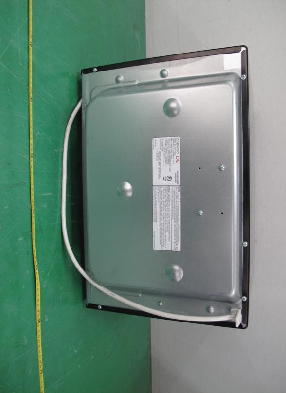
C5F7NF1CMO900N
Nov 23, 2014Microwave Oven
Equipment Class
8CC - Part 18 Consumer Device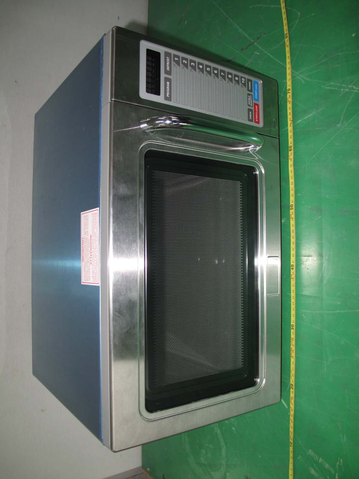
C5F7NF9PMO100N
Mar 25, 2013Commercial Microwave Oven
Equipment Class
8CC - Part 18 Consumer Device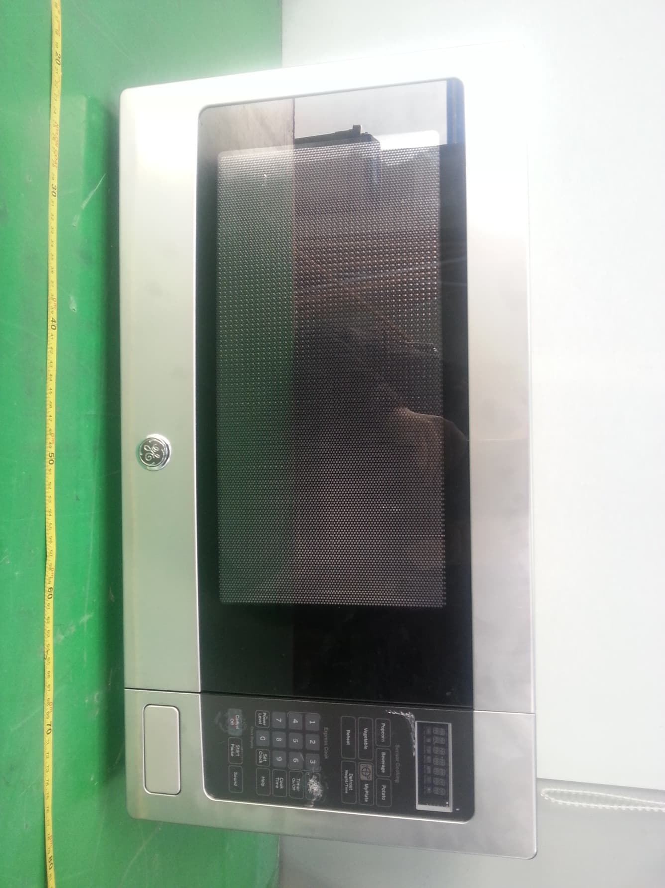
C5F7NF22MO110N
Jan 23, 2013Microwave Oven
Equipment Class
8CC - Part 18 Consumer Device
C5F7NF9FMO120N
May 06, 2012Commercial Microwave Oven
Equipment Class
8CC - Part 18 Consumer Device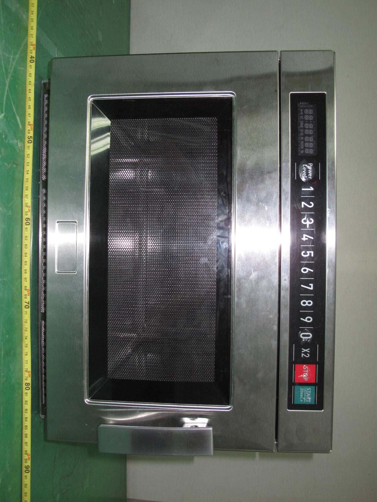
C5F7NF9FMO180N
Sep 05, 2011Commercial Microwave Oven
Equipment Class
8CC - Part 18 Consumer Device