C5F7NFCMC907DMonitor
WINIA Electronics Co., Ltd.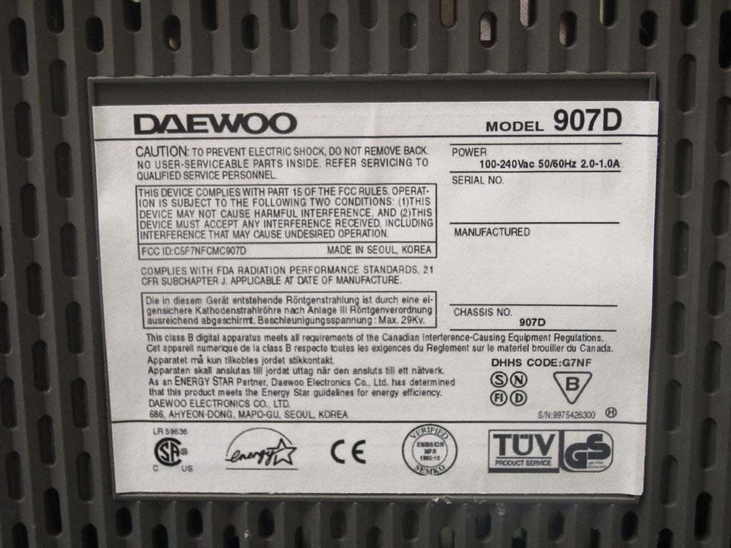
Click to zoom
Application Details
- Equipment Class
- JBP - Part 15 Class B Computing Device Peripheral
- Date of Grant
- Aug 25, 2002
- Application Purpose
- Original Equipment
- Date of Application
- Aug 25, 2002
- Equipment Note
- Monitor
- Company
- WINIA Electronics Co., Ltd.
- Country
- South Korea
Documents & Files
Document Text
Text extracted from the exhibit documents filed with the FCC. Open a document above to read the original.
Users Manual
Model No : 907D/907DF USER’S GUIDE http://www.dwe.co.kr COLOR MONITOR WICHTIGE INFORMATIONEN Bitte lesen Sie alle diese Informationen, bevor Sie das Gerät in Betriebnehmen! Lesen Sie außerdem die Bedienungsanleitung komplett undsorgfältig durch, da nur in diesem Fall eine problemlose Inbetriebnahmeerwartet werden kann. Achten Sie darauf, daß das Gerät nur in eine 230V Steckdoseeingesteckt wird. Die Steckdose sollte jederzeit frei zugänglich sein um bei einem evtl.auftretenden Notfall das Gerät schnell vom Netz zu trennen. Achten Sie desweiteren darauf, daß die Netzanschlußleitung nichtmechanisch beansprucht oder sonstwie beschädigt wird. Öffnen Sie das Gerät niemals! Im Inneren befinden sich Teile mitgefährlicher Spannung. Bevor Sie das Gerät reinigen, ziehen Sie bitte den Netzstecker aus derSteckdose. Säubern Sie dann das Gerät mit einem feuchten (keinesfallstropfnassen) Lappen. Stellen Sie das Gerät an einem ergonomisch günstigen Ort auf undsorgen Sie dafür, daß der Monitor mit nach ISO 9241 -3, -7, -8geprüfter Peripherie betrieben wird, da nur unter diesen Umständen einoptimaler ergonomischer Betrieb des Gerätes sichergestellt ist. Falls Sie dennoch Fragen haben, auf die die Bedienungsanleitung keinehinreichende Antwort geben kann, so kontaktieren Sie bitte den nächstenFachhändler. Maschinenlärminformationsverordnung 3. GSGV, 18.01 1991:Der arbeitsplatzbezogene Schalldruckpegel beträgt 70 dB (A) oderwenigergemäß ISO 7779. FEDERAL COMMUNICATIONS COMMISSION RADIO FREQUENCY INTERFERENCE STATEMENT NOTE : This equipment has been tested and found to comply with the limits for a Class B digital device, pursuant to Part 15 of the FCC Rules. Theselimits are designed to provide reasonable protection against harmfulinterference in a residential installation. This equipment generates, uses andcan radiate radio frequency energy and, if not installed and used inaccordance with the instructions, may cause harmful interference to radiocommunications. However, there is no guarantee that interference will notoccur in a particular installation. If this equipment does cause harmfulinterference to radio or television reception, which can be determined byturning the equipment off and on, the user is encouraged to try to correct theinterference by one or more of the following measures : - Reorient or relocate the receiving antenna. - Increase the separation between the equipment and receiver. - Connect the equipment to an outlet on a circuit different from that to which the receiver is connected. - Consult the dealer or an experienced radio or TV technician for help. CAUTION : Any changes or modifications not expressly approved by the party responsible for compliance could void the user ’ s authority to operate the equipment. CANADIAN NOTICEAVIS CANADIEN This Class B digital apparatus meets all requirements of the CanadianInterference-Causing Equipment Regulations. Cet appareil numérique de la Class B respecte toutes les exigences duRèglement sur le matériel brouilleur du Canada. DECLARATION OF CONFORMITY We, Manufacturer / Importer DAEWOO ELECTRONICS CO., Ltd 686, Ahyon-dong, Mapo-gu, Seoul, Korea declare under our sole responsibility that the product, Color Display monitor 907D 907DF to which this declaration relates is in conformity with the following standard(s) or other normative document(s) Safety : EN60950/1992/A1:1993/A2:1993 A3:1995/A4:1997 EMC : EN 55022/8.1994/A1:1995/A2:1997 EN 55024/1998 EN 61000 -3-2,3/1995 following the provisions of 89/336 EEC-EMC Directive and the provisions of 73/23 EEC-Low Voltage Directive. Handed over by : Jong K. Choi, Director. Display Business Division. 2002 Seoul Signature : J.K.Choi Director. Display Business Division. DAEWOO ELECTRONICS CO., LTD. Emission Characteristics Tested by SEMKOA sample of this type has been tested and has shown compliance withtheguidelines in the swedish document MPRII.This product is also designed for IT power system with phase to phasevoltage of 230V. The power cord is used as a main disconnect device. Disconnect thepower cord before servicing. The outlet must be installed near themonitor and must be easily accessible.As an E NERGY S TAR ® Partner, Daewoo Electronics Co., Ltd. has determined that this product meets the Energy Star ® guidelines for energy efficiency.The appliance is not intended for use by young children or infirmpersons without supervision ;Young children should be supervised to ensure that they do not playwith the appliance. English - 1 INTRODUCTION INTRODUCTION This manual explains how to correctly install, operate and get thebest performance from your monitor. Please read this user’sguide carefully before installing your monitor, then keep it nearyour monitor for quick reference. First, please check that the contents of the box corresponds withthe following checklist : Color monitor Power cord User’s Guide Warranty card (Optional) If any item is missing or damaged, please contact your dealer.Please keep the box and packing materials so that you mayproperly store or transport your monitor. CONTENTS CONTENTS Introduction ............................................................................. 1 Product Features ................................................................. 2 Setup ......................................................................................... 3 Connecting the Signal Cable and Power Cord..................... 3 Operation & Adjustment ...................................................... 4 Specifications ........................................................................... 9 Factory Preset Timings ........................................................... 9 Troubleshooting ..................................................................... 10 English - 2 English - 3 PRODUCT FEATURES Signal Cable Power Cord 1. Turn off the computer and monitor.2. Connect the 15 pin D-sub connector to the output port of the video card in your computer. 3. Tighten the screws of the connector.4. Pl…
Text truncated - open the document above for the full version.
Block Diagram
907D MONITOR BLOCK DIAGRAM FBT (HITACHI) VIDEO D-SUB RGB H/V VIDEO PRE AMP LM1237(NS) VIDEO OUT AMP LM2463(NS) HV DRIVE / CONTROL MCU WT62P2 (WELTREND) H/V OSC Processor TDA4856 (PHILIPS) Geometrical Compensation H-Driver Drive Transformer H/V Moire Cancellation USB-PORT 1 Up Stream 4 Down Stream AC INPUT SMPS Transformer H/Def Output TR/Damper C/S Switching FJAF6815(F/C) DD54RC Auto H/Linearity OP-Amp V-Driver KA4863A (PHILIPS) IIC Control PWM D/A CRT SOCKET FOCUS-UNIT FBT IIC Control DYNA MIC 190V 80V +14V -14V HT 5V FOCUS OUTPUT C5042F ( SAMSUNG ) 50~160Hz 30~95KHz 50~160Hz 30~95KHz 30~95KHz 50~160Hz 30~95KHz 30~95KHz 30~95KHz 50~160Hz
Block Diagram
907D MONITOR BLOCK DIAGRAM FBT (HITACHI) VIDEO D-SUB RGB H/V VIDEO PRE AMP LM1237(NS) VIDEO OUT AMP LM2463(NS) HV DRIVE / CONTROL MCU WT62P2 (OSC=12MHZ) (WELTREND) H/V OSC Processor TDA4856 (PHILIPS) Geometric al Compensat H-Driver Drive Transformer H/V Moire Cancellati on USB-PORT 1 Up Stream 4 Down Stream AC INPUT SMPS Transformer H/Def Output TR/Damper C/S Switching FJAF6815(F/ C) DD54RC Auto H/Linearit y O P-Amp V-Driver KA4863A (PHILIPS) IIC Control PWMD/A CRT SOCKET FOCUS-UNIT FBT IIC Contro l DYNAM IC FOCUS 190V 80V +14V-14V HT5V FOCUS OUTPUTC5042F (SAMSUNG) 50~160Hz 50~160Hz 30~95KHz 30~95KHz 50~160Hz 30~95KHz RGB 30~95KHz 50~160Hz 30~95KHz SDA 50~160Hz RGB RGB SCL SCL SDA 30~95KHz 30~95KHz 30~95KHz 30~95KHz H.V SCL SDA 50~160 Hz
Cover Letter(s)
letter to ist.jpg (1076x1328x24b jpeg)
ID Label/Location Info
ID Label Sample & Location Information
Operational Description
Operational Description of 907D 1. Power Supply Circuit 1) AC Inlet (EMI Filter) The AC power is supplied to the Inlet Socket and EMI Filtering circuit consists of two X-caps, three Y-caps and Line filters. This filter reduces the conductor noise through power line. 2) Bridge Rectifier Circuit This circuit converts AC input voltage into DC voltage by rectifying through bridge diode (location D101, D102, D103, D104) and bulk capacitor (C005) 3) Output Voltage The power supply circuit makes DC output voltages : 5V, 6.3V, -15V, 12V, 15V, 80V,190V 4) Power ON/OFF When the voltages of the Microprocessor pin #20 and pin #21 become high levels, Q102 turns on and then DC voltage is supplied to the boards and the state becomes power-on. 2. Horizontal & Vertical Oscillation Circuit The H/V Oscillation IC TDA4856 makes Horizontal drive pulse for Horizontal drive circuit and Vertical ramp pulse for Vertical driver TDA4863A. The Horizontal drive pulse frequency range is from 30KHz to 95KHz. The Horizontal drive pulse is applied to Horizontal drive transistor Q539. When the vertical sync is supplied to IC TDA4856 pin #12 and #13, Vertical ramp pulse is made. 3. Microprocessor The microprocessor applied to this monitor is made in Weltrend and the name is WT62P2. The following is the major function of the microprocessor. - H/V sync processing, Power on/off, DPMS function. - CS port output, Recall, Degaussing function. - OSD, H/V OSC, Video preamp IC control. The operational clock of the microprocessor is 12MHz and It has I2C Interface to control above ICs. 4. Horizontal drive and Output part The output of Horizontal oscillator goes out of the pin #8 of IC TDA4856 and it is applied to the base of Horizontal drive transistor Q539. A large amount of drive current necessary for horizontal output transistor Q539 is made by T501 (Horizontal drive transformer). Q539 is switched by pulse voltage provided by T501 and when on-time pulse is charged on the base of Q539, Q539 turns on and has collector current flow which increases linearly through horizontal deflection coil. At the moment of off-time, pulse is charged on the base of Q507, collector current stops increasing and it turns off. All the above chain of actions becomes a cycle and it goes on and on. As for the high voltage of FBT, The output of IC601 KA7500B goes to the gate of high voltage drive transistor Q608 and then the high voltage of FBT is obtained from the same methods that the horizontal output voltage is. 5. Video Preamp and OSD processing The analog R,G,B signal is supplied from signal source and passes through capacitors C801, C831, C861 and is applied to the pin#5, #6, #7 of the Video Preamp IC (LM1237). Preamp IC has built-in OSD function and controls OSD function by I2C bus with the microprocessor. 6. CRT Output Driver and Bias Circuit This video output circuit consists of the 3-channel video outputamp IC and the Bias IC LM2480. Its bias voltage is about 80 volts and the output gain is obtained from the preamp output voltage level controlled by the micro- processor.
Test Report
File No. 02-IST-044/FB IST EMC LAB. Page 1 of 17 IST EMC Lab. San 21-8 Goan-Ri, Baekam-Myun, Yongin-Si, Kyunggi-Do, KOREA International - Tel : 82-31 - 333 - 4093. Fax : 82-31 - 333 - 4094. Domestic - Tel : 031 - 333 - 4093. Fax : 031 - 333 - 4094. IST EMC LAB. EMISSION TEST REPORT Test report file No. : 02-IST-044/FB Date of issue : Mar. 08, 2002 Model / Type No. : 907D ■ Basic □ Alternate Kind of product Brand name Applicant Manufacturer License holder Address : 19” Color Display Monitor : Daewoo : Daewoo Electronics Co., Ltd. Display Business Division : Daewoo Electronics Co., Ltd. Display Business Division : Daewoo Electronics Co., Ltd. Display Business Division : 543, Dangjung-Dong, Kunpo-City, Kyonggi-Do, Korea Test result according to the regulation(s) Positive Negative at page 3. This test report with appendix consists of 17 pages. The test result only responds to the tested sample. It is not allowed to copy this report even partly without the allowance of the Test Laboratory. This equipment is complied with the applicable technical standards as indicated in the measurement report and was tested in accordance with the measurement procedures specified in ANSI C63.4-1992. File No. 02-IST-044/FB IST EMC LAB. Page 2 of 17 IST EMC Lab. San 21-8 Goan-Ri, Baekam-Myun, Yongin-Si, Kyunggi-Do, KOREA International - Tel : 82-31 - 333 - 4093. Fax : 82-31 - 333 - 4094. Domestic - Tel : 031 - 333 - 4093. Fax : 031 - 333 - 4094. DIRECTORY A) Documentation. Page Directory Test regulations Information of Test Regulation Equipment under Test Test Conditions Test Result Measurement Uncertainty Test-setup Summary 2 3 3 4 5 ~ 6 7 8 9 ~ 11 17 B) Test Data. Conducted emissions (Mains) Radiated emissions : 450 kHz - 30 MHz : 30 MHz – 1 GHz 12 ~ 14 15 ~ 16 C) Appendix File No. 02-IST-044/FB IST EMC LAB. Page 3 of 17 IST EMC Lab. San 21-8 Goan-Ri, Baekam-Myun, Yongin-Si, Kyunggi-Do, KOREA International - Tel : 82-31 - 333 - 4093. Fax : 82-31 - 333 - 4094. Domestic - Tel : 031 - 333 - 4093. Fax : 031 - 333 - 4094. TEST REGULATIONS The tests were performed according to the following regulations ; ■ - FCC Part 15, Subpart B (Unintentional Radiators, Class B) Information of Test Laboratory IST EMC Lab. San 21-8 Goan-Ri, Baekam-Myun, Yongin-Si, Kyunggi-Do, Korea International - Tel : 82-31 - 333 - 4093. Fax : 82-31 - 333 - 4094. Domestic - Tel : 031 - 333 - 4093. Fax : 031 - 333 - 4094. File No. 02-IST-044/FB IST EMC LAB. Page 4 of 17 IST EMC Lab. San 21-8 Goan-Ri, Baekam-Myun, Yongin-Si, Kyunggi-Do, KOREA International - Tel : 82-31 - 333 - 4093. Fax : 82-31 - 333 - 4094. Domestic - Tel : 031 - 333 - 4093. Fax : 031 - 333 - 4094. EQUIPMENT UNDER TEST Equipment Description : CDT : Orion CDT CDT Size: 19 inch Diagonal visible image area: 18 inch Dot Pitch: 0.25 mm Frequency Range : Vertical: 50 ~ 160 Hz, Horizontal: 30 ~ 95 kHz Plug and Play : VESA DDC Compatible Power Saving : EPA, VESA DPMS, Nutek Compliant Power Supply Input : 100 ~ 240 Vac, 50/60 Hz (Free Voltage) Power consumption : 120 W Dimensions (W x H x D) : 444 x 459.5 x 460 (set with stand) EUT Type : Table-Top. Floor-Standing. Table-Top and Floor-Standing(Combination). Operation – mode of the E.U.T. : The equipment under test was operated during the measurement under following conditions : Standby. Operational Condition : Scrolling “H” characters under MS Windows 98, Test mode : 1600 X 1200, 75 Hz Configuration of the equipment under test : Following peripheral devices and interface cables were connected during the measurement : Equipment Type Brand Serial No. PC Brio BA600/550 HP SG01901711 Keyboard SK-2502C HP M0004102892 Mouse1 M-S48A HP LZE01252034 Printer A0302384 Northern Telecom 2633S60168 Mouse2 M-MD14-2 Logitech N/A Connecting Interface Cables : - Unshielded AC power cable : 1.8 m - Shielded monitor’s signal cable : 1.5 m - Shielded printer’s signal cable : 1.5 m File No. 02-IST-044/FB IST EMC LAB. Page 5 of 17 IST EMC Lab. San 21-8 Goan-Ri, Baekam-Myun, Yongin-Si, Kyunggi-Do, KOREA International - Tel : 82-31 - 333 - 4093. Fax : 82-31 - 333 - 4094. Domestic - Tel : 031 - 333 - 4093. Fax : 031 - 333 - 4094. TEST CONDITIONS The measurement of the conducted emissions (Interference voltage) was performed in a shielded room. Test location : Shielded room. No.1 Compact chamber 2 Used testing instruments : Name Type Manufacturer Calibration. Date Serial Number ESH 3 Test Receiver Rohde & Schwarz Jun. 16, 2001 861742/015 3725/2 LISN EMCO Jul. 30, 2001 9101-2068 KNW-407 LISN Hyup-Rip Jul. 26, 2001 8-883-10 ESH 3-Z2 Pulse Limiter Rohde & Schwarz Jul. 13, 2001 357.8810.52 Test - accessories : Type Manufacturer Aneroid Barometer Sato Hygrometer Sato Measurement Procedures : Conducted emissions measurments were made in accordance with ANSI C-63.4-1992, “Method of Measurement of Radio-Noise Emissions from Low-Voltage Electrical and Electronic Equipment in the Range of 9 kHz to 40 GHz”. The measurement were performed over the frequency range of 0.45MHz to 30MHz using a 50 Ω /50uH LISN as the input transducer to an EMI/Field Intensity Meter. The measurements were made with the detector set for “Peak” amplitude within an IF bandwidth of 10kHz or for “quasi-peak” within a bandwidth of 9kHz. All used test-instruments as well as the test-accessories are calibrated regularly. File No. 02-IST-044/FB IST EMC LAB. Page 6 of 17 IST EMC Lab. San 21-8 Goan-Ri, Baekam-Myun, Yongin-Si, Kyunggi-Do, KOREA International - Tel : 82-31 - 333 - 4093. Fax : 82-31 - 333 - 4094. Domestic - Tel : 031 - 333 - 4093. Fax : 031 - 333 - 4094. The measurement of the radiated emissions (Electric field) in the frequency range from 30 MHz to 1GHz was performed in horizontal and vertical antenna polarization at a open-site which meet the site attenuation requirement of ANSI C63.4-1992 and a test distance of : Location : Open Site No. 1 Open Site No. 2 Open Site No. 3 Distance : 3 meters 10 meters Used testing instruments : Name Type Manufacturer Calibration. Date Serial Number ESVP …
Text truncated - open the document above for the full version.
Contact Information
Applicant
Youjin Choi(Manager)
Technical Contact
Daewoo Electronics Co., Ltd.Moon Myung-Jin
[email protected]82-31-428-5561
543 Dangjeong-Dong · Kyonggi-Do · South Korea
Non-Technical Contact
IST Co., Ltd.Joon H Lee
[email protected]82-31-333-4093
Test Firm
IST Co., LtdBong Kyoon Bae
Technical Specifications
| # | Rule Parts | Frequency Range | Power Output |
|---|---|---|---|
| 1 | 15B | - | - |
Other Applications from WINIA Electronics Co., Ltd.
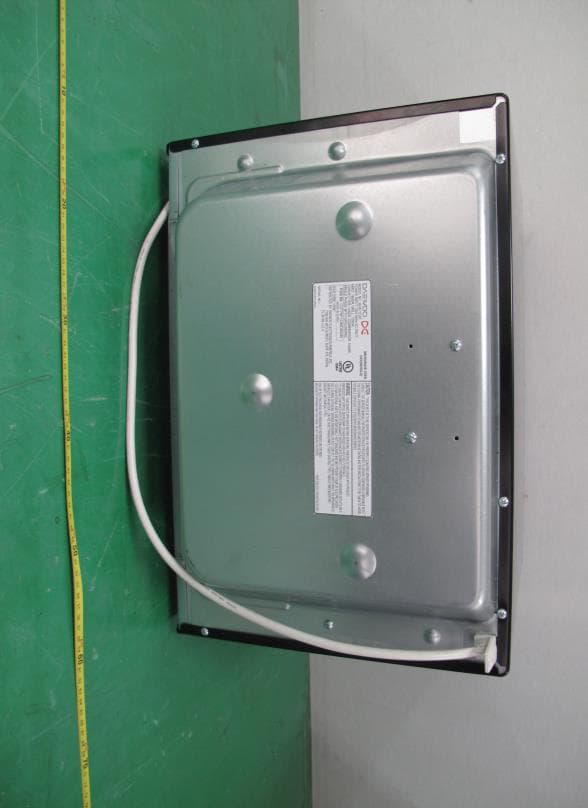
C5F7NF1CMO900N
Nov 23, 2014Microwave Oven
Equipment Class
8CC - Part 18 Consumer Device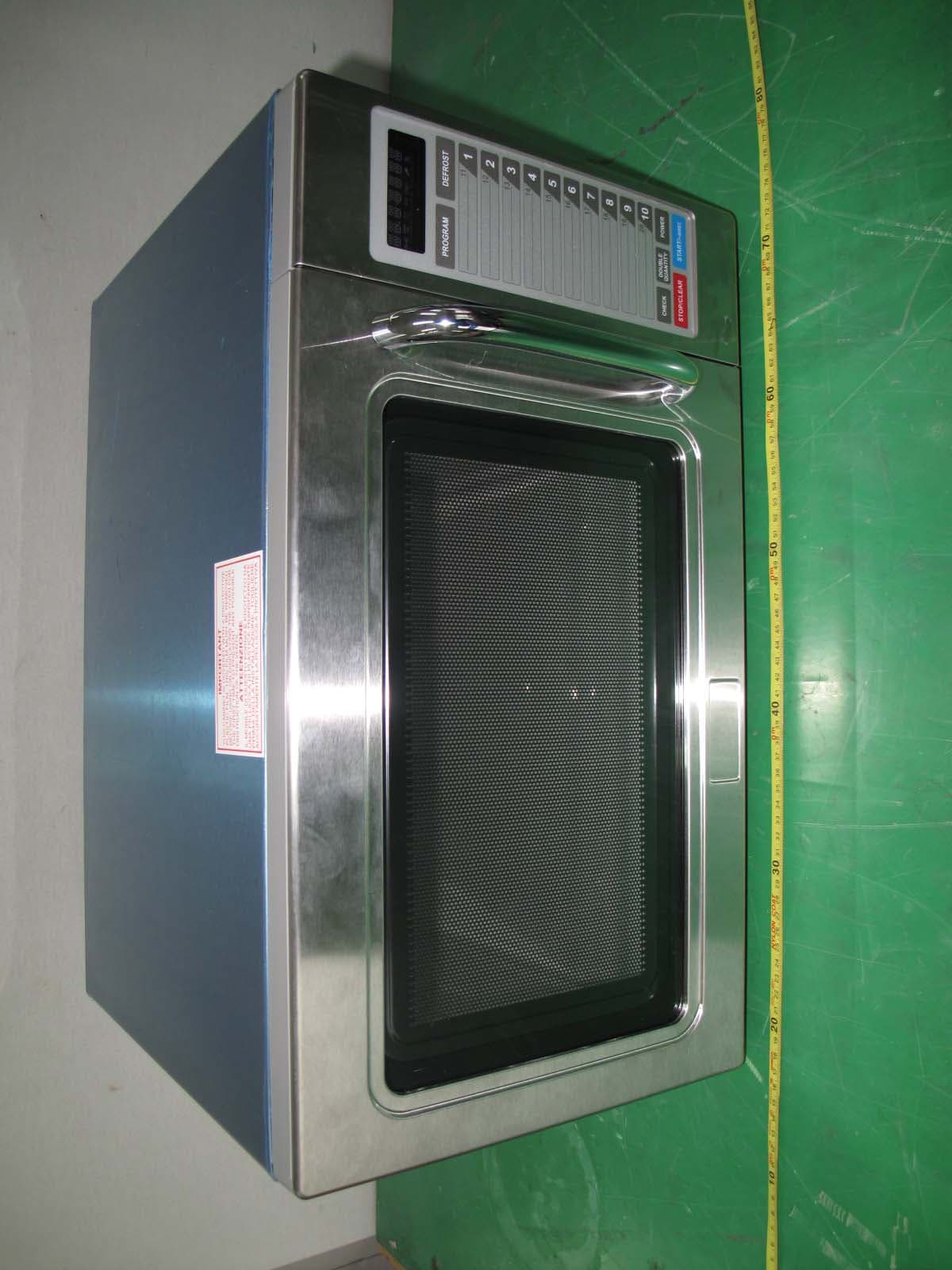
C5F7NF9PMO100N
Mar 25, 2013Commercial Microwave Oven
Equipment Class
8CC - Part 18 Consumer Device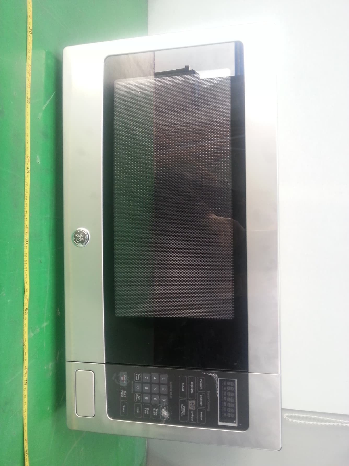
C5F7NF22MO110N
Jan 23, 2013Microwave Oven
Equipment Class
8CC - Part 18 Consumer Device
C5F7NF9FMO120N
May 06, 2012Commercial Microwave Oven
Equipment Class
8CC - Part 18 Consumer Device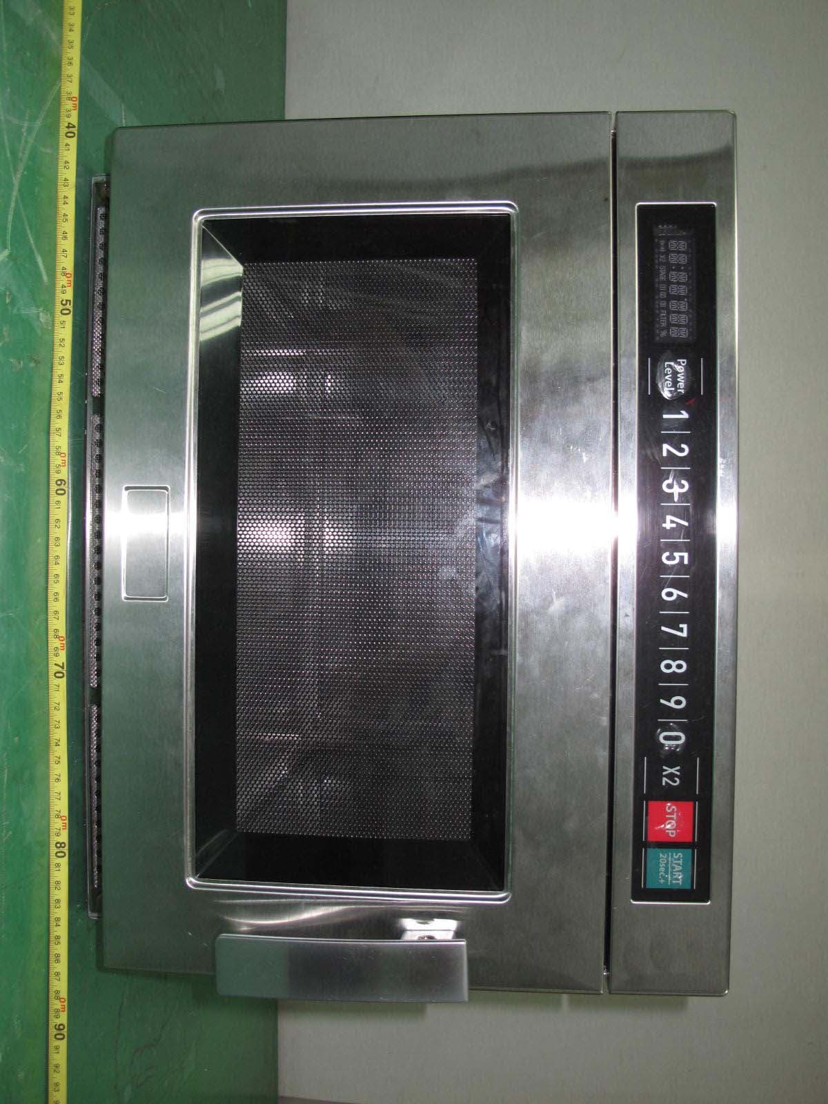
C5F7NF9FMO180N
Sep 05, 2011Commercial Microwave Oven
Equipment Class
8CC - Part 18 Consumer Device