C5F7NFCML520BAVLCD Monitor
WINIA Electronics Co., Ltd.
Click to zoom
Application Details
- Equipment Class
- JBP - Part 15 Class B Computing Device Peripheral
- Date of Grant
- Feb 26, 2002
- Application Purpose
- Original Equipment
- Date of Application
- Feb 26, 2002
- Equipment Note
- LCD Monitor
- Company
- WINIA Electronics Co., Ltd.
- Country
- South Korea
Documents & Files
Document Text
Text extracted from the exhibit documents filed with the FCC. Open a document above to read the original.
Users Manual
http://www.dwe.co.kr TFT LCD-MONITORModel No : L520BAV USER’S GUIDE WICHTIGE INFORMATIONEN Bitte lesen Sie alle diese Informationen, bevor Sie das Gerät in Betriebnehmen! Lesen Sie sich außerdem die Bedienungsanleitung komplett undsorgfältig durch, da nur in diesem Fall eine problemlose Inbetriebnahmeerwartet werden kann. Achten Sie darauf, daß das Gerät nur in eine 230V Schuko-Steckdoseeingesteckt wird. Die Steckdose sollte jederzeit frei zugänglich sein um bei einem evtl.auftretenden Notfall das Gerät schnell vom Netz zu trennen. Achten Sie desweiteren darauf, daß die Netzanschlußleitung nichtmechanisch beansprucht oder sonstwie beschädigt wird. Offnen Sie das Gerät niemals! Im Inneren befinden sich Teile mitgefährlicher Spannung. Bevor Sie das Gerät reinigen, ziehen Sie bitte den Netzstecker aus derSteckdose. Säubern Sie dann das Gerät mit einem feuchten (keinesfallstropfnassen) Lappen. Stellen Sie das Gerät an einem ergonomisch günstigen Ort auf undsorgen Sie dafür, daß der Monitor mit nach ISO 9241 -3, -7, -8geprüfter Peripherie betrieben wird, da nur unter diesen Umständen einoptimaler ergonomischer Betrieb des Gerätes sichergestellt ist. Falls Sie dennoch Fragen haben, auf die die Bedienungsanleitung keinehinreichende Antwort geben kann, so kontaktieren Sie bitte den nächstenFachhändler.Maschinenlärminformationsverordnung 3. GSGV, 18.01 1991:Der arbeitsplatzbezogene Schalldruckpegel beträgt 70 dB (A) oderwenigergemäß ISO 7779. FEDERAL COMMUNICATIONS COMMISSION RADIO FREQUENCY INTERFERENCE STATEMENT NOTE : This equipment has been tested and found to comply with the limits for a Class B digital device, pursuant to Part 15 of the FCC Rules. Theselimits are designed to provide reasonable protection against harmfulinterference in a residential installation. This equipment generates, uses andcan radiate radio frequency energy and, if not installed and used inaccordance with the instructions, may cause harmful interference to radiocommunications. However, there is no guarantee that interference will notoccur in a particular installation. If this equipment does cause harmfulinterference to radio or television reception, which can be determined byturning the equipment off and on, the user is encouraged to try to correct theinterference by one or more of the following measures :- Reorient or relocate the receiving antenna.- Increase the separation between the equipment and receiver. - Connect the equipment to an outlet on a circuit different from that to which the receiver is connected. - Consult the dealer or an experienced radio or TV technician for help. CAUTION : Any changes or modifications not expressly approved by the party responsible for compliance could void the user ’ s authority to operate the equipment. CANADIAN NOTICEAVIS CANADIEN This Class B digital apparatus meets all requirements of the CanadianInterference-Causing Equipment Regulations.Cet appareil numérique de la Class B respecte toutes les exigences duRèglement sur le matériel brouilleur du Canada. DECLARATION OF CONFORMITY We, Manufacturer / Importer DAEWOO ELECTRONICS CO., Ltd 541, 5-Ga, Namdaemoon-Ro, Jung-Gu Seoul, Korea declare under our sole responsibility that the product, TFT LCD monitor L520BAV to which this declaration relates is in conformity with the following standard(s) or other normative document(s) Safety : EN60950/1992/A1:1993/A2:1993 A3:1995/A4:1997 EMC : EN 55022/8.1994/A1:1995/A2:1997 EN 55024/1998 EN 61000 -3-2,3/1995 following the provisions of 89/336 EEC-EMC Directive and the provisions of 73/23 EEC-Low Voltage Directive. Handed over by : Jong K. Choi, Director. Display Business Division. Dec, 2001 Seoul Signature : J.K.Choi Director. Display Business Division.DAEWOO ELECTRONICS CO., LTD. Emission Characteristics Tested by SEMKOA sample of this type has been tested and has shown compliance withtheguidelines in the swedish document TCO 99.This product is also designed for IT power system with phase to phasevoltage of 230V. The power cord is used as a main disconnect device. Disconnect thepower cord before servicing. The outlet must be installed near themonitor and must be easily accessible.As an E NERGY S TAR ® Partner, Daewoo Electronics Co., Ltd. has determined that this product meets the Energy Star ® guidelines for energy efficiency.The appliance is not intended for use by young children or infirmpersons without supervision ;Young children should be supervised to ensure that they do not playwith the appliance. CONTENTS CONTENTS Introduction ............................................................................. 1 Product Features ................................................................. 2 Setup ......................................................................................... 3 Installing the Stand .............................................................. 3Connecting the 15 Pin Signal Cable and Power Cord ......... 4Connecting the Speakers ......................................................5Connecting the Others .........................................................7 Operation & Adjustment ...................................................... 8 Specifications ......................................................................... 16 Factory Preset Timings ......................................................... 18 Changing the Stand ............................................................... 19 Troubleshooting ..................................................................... 21 Appendix Description for D-sub Connector English - 1 INTRODUCTION INTRODUCTION This manual explains how to correctly install, operate and get thebest performance from your monitor. Please read this user’sguide carefully before installing your monitor, then keep it nearyour monitor for quick reference. First, please check that the contents of the box corresponds withthe following checklist : TFT LCD monitor Power cord15 pin signal cableAudio cable (mini-jack)SpeakerUser’s guide …
Text truncated - open the document above for the full version.
Block Diagram
DC CML-520BM CML-520BAV CML-520BTV 2 12V 5 1 3.3V 10 12V, 5Vs, 5VD, 5VA, 3.3VD 2 R,L 3 8 AUDIO OUT AC INLET 100 ~240V 50/60Hz CVBS / S- VIDEO 4 48 DOT CLOCK TMDS ON/OFF 24 36 VIDEO SIGNA L DIGITAL SIGNAL H/V SYNC. RGB SIGNAL POWER ON/OFF DIMMING CONTROL INVERTER ON/OFF R,G,B Dual 6bit Scaler ASI310 ADC TDA8752 TMDS Sil143 (Option) CML-520BDV Decoder SAA7114 (Option) CML-520BAV CML-520BTV Output Video Rate -H:48~62KHz. V:60~75Hz -Resolution:only 1024*768 -Dot clock: 65~80MHz LCD Panel L150X2 Key Control PCB U-Com MTV312MV64 Power PCB Inverter Speaker(L/R) I/O PCB MAIN PCB D-SUB DVI CML-520BDVI VIDEO CML-520BAV R(8),G(8) ,B(8) AUDIO PROCESSOR L520B* BLOCK DIAGRAM I2C H/V SYNC. / DOT CLOCK /Out Enable AC IN ADC ON/OFF DECODE R ON/OFF 74ACT14 SYNC. BUFFER H/V SYNC. TMDS SIGNAL H/V SYNC. 24C21 Input Viedo Rate -H:30~62KHz. V: 56~75Hz -Resolution: Up to 1024*768 DIGITAL SIGNAL CVBS / S-VHS 12V 3 8 TV TUNER DTI-FNF05A (Option) CML-520BTV 1 KEY CONTROL TV CML-520BTV IR CML-520BTV 5 Audio R,L 24.576MHz 14.318MHz 12.00MHz FX8-80P-SV Connector wafer
ID Label/Location Info
ID Label Sample & Location Information
Test Report
File No. 02-IST-024/FB IST EMC LAB. Page 1 of 23 IST EMC Lab. San 21-8 Goan-Ri, Baekam-Myun, Yongin-Si, Kyunggi-Do, KOREA International - Tel : 82-31 - 333 - 4093. Fax : 82-31 - 333 - 4094. Domestic - Tel : 031 - 333 - 4093. Fax : 031 - 333 - 4094. IST EMC LAB. EMISSION TEST REPORT Test report file No. : 02-IST-024/FB Date of issue : Feb. 15, 2001 Model / Type No. : L520BAV ■ Basic □ Alternate Kind of product Brand name Applicant Manufacturer License holder Address : LCD Monitor : Daewoo : Daewoo Electronics Co., Ltd. Display Business Division : Daewoo Electronics Co., Ltd. Display Business Division : Daewoo Electronics Co., Ltd. Display Business Division : 543, Dangjung-Dong, Kunpo-City, Kyonggi-Do, Korea Test result according to the regulation(s) Positive Negative at page 3. This test report with appendix consists of 23 pages. The test result only responds to the tested sample. It is not allowed to copy this report even partly without the allowance of the Test Laboratory. This equipment is complied with the applicable technical standards as indicated in the measurement report and was tested in accordance with the measurement procedures specified in ANSI C63.4-1992. File No. 02-IST-024/FB IST EMC LAB. Page 2 of 23 IST EMC Lab. San 21-8 Goan-Ri, Baekam-Myun, Yongin-Si, Kyunggi-Do, KOREA International - Tel : 82-31 - 333 - 4093. Fax : 82-31 - 333 - 4094. Domestic - Tel : 031 - 333 - 4093. Fax : 031 - 333 - 4094. DIRECTORY A) Documentation. Page Directory Test regulations Information of Test Laboratory Equipment under Test Test Conditions Test Result Test-setup (Drawings) Test-setup (Photos) Summary 2 3 3 3 ~ 4 5 ~ 6 7 8 9 ~ 10 16 ~ 17 23 B) Test Data. Conducted emissions (Mains) Radiated emissions : 450 kHz - 30 MHz : 30 MHz – 1 GHz 11 ~ 13 18 ~ 20 14 ~ 15 21 ~ 22 C) Appendix File No. 02-IST-024/FB IST EMC LAB. Page 3 of 23 IST EMC Lab. San 21-8 Goan-Ri, Baekam-Myun, Yongin-Si, Kyunggi-Do, KOREA International - Tel : 82-31 - 333 - 4093. Fax : 82-31 - 333 - 4094. Domestic - Tel : 031 - 333 - 4093. Fax : 031 - 333 - 4094. TEST REGULATIONS The tests were performed according to the following regulations ; ■ - FCC Part 15, Subpart B (Unintentional Radiators, Class B) Information of Test Laboratory IST EMC Lab. San 21-8 Goan-Ri, Baekam-Myun, Yongin-Si, Kyunggi-Do, Korea International - Tel : 82-31 - 333 - 4093. Fax : 82-31 - 333 - 4094. Domestic - Tel : 031 - 333 - 4093. Fax : 031 - 333 - 4094. EQUIPMENT UNDER TEST Equipment Description : LCD Pannel : 15.0 inch TFT LCD Pixel Pinch 0.297 x 0.297 mm Frequency Range : Vertical 50 ~ 75 Hz, Horizontal 30 ~ 62 kHz Vedio Bandwidth : 80 MHz PC Input Signal : H / V separated (TTL) 15 pin mini D-Sub (Analog RGB) AV Input Signal : Video - CVBS, S-VHS input Audio1 - Left,Right Stereo RCA Audio2 - mini jact for sound card Speaker : Maximum output 6 W (L-3W, R-3W) Input signal – 100 mV, 8 ohm Power Supply Input : 100 ~ 240 Vac, 50/60 Hz Power consumption : 26 W Micom Type : MTV312MV64 (MYSON) – clock 12 MHz Dimensions (W x H x D) : 370 x 352 x 205 mm (with stand) File No. 02-IST-024/FB IST EMC LAB. Page 4 of 23 IST EMC Lab. San 21-8 Goan-Ri, Baekam-Myun, Yongin-Si, Kyunggi-Do, KOREA International - Tel : 82-31 - 333 - 4093. Fax : 82-31 - 333 - 4094. Domestic - Tel : 031 - 333 - 4093. Fax : 031 - 333 - 4094. EQUIPMENT UNDER TEST EUT Type : Table-Top. Floor-Standing. Table-Top and Floor-Standing(Combination). Operation – mode of the E.U.T. : The equipment under test was operated during the measurement under following conditions : Standby. Operational Condition : 1) Scrolling “H” characters under MS Windows 98, Test mode : 1024 X 768, 75 Hz (60 kHz) 2) Displaying color bar and sounding 1 kHz audio Configuration of the equipment under test : Following peripheral devices and interface cables were connected during the measurement : Equipment Type Brand Serial No. PC Brio BA600/550 HP SG01902402 Keyboard SK-2502C HP M0004102821 Mouse1 M-S48A HP LZE01251424 Printer A0302384 Northern Telecom 26633S60168 Mouse2 M-MD14-2 Logitech N/A Pattern Generator PM5418 Fluke 945205418003 Connecting Interface Cables : - Unshielded AC power cable : 1.8 m - Shielded monitor’s signal cable : 1.5 m - Shielded printer’s signal cable : 1.5 m File No. 02-IST-024/FB IST EMC LAB. Page 5 of 23 IST EMC Lab. San 21-8 Goan-Ri, Baekam-Myun, Yongin-Si, Kyunggi-Do, KOREA International - Tel : 82-31 - 333 - 4093. Fax : 82-31 - 333 - 4094. Domestic - Tel : 031 - 333 - 4093. Fax : 031 - 333 - 4094. TEST CONDITIONS The measurement of the conducted emissions (Interference voltage) was performed in a shielded room. Test location : Shielded room. No.1 Compact chamber 2 Used testing instruments : Name Type Manufacturer Calibration. Date Serial Number ESH 3 Test Receiver Rohde & Schwarz Jun. 16, 2001 861742/015 3725/2 LISN EMCO Jul. 30, 2001 9101-2068 KNW-407 LISN Hyup-Rip Jul. 26, 2001 8-883-10 ESH 3-Z2 Pulse Limiter Rohde & Schwarz Jul. 13, 2001 357.8810.52 Test - accessories : Type Manufacturer Aneroid Barometer Sato Hygrometer Sato Measurement Procedures : Conducted emissions measurments were made in accordance with ANSI C-63.4-1992, “Method of Measurement of Radio-Noise Emissions from Low-Voltage Electrical and Electronic Equipment in the Range of 9 kHz to 40 GHz”. The measurement were performed over the frequency range of 0.45MHz to 30MHz using a 50 Ω /50uH LISN as the input transducer to an EMI/Field Intensity Meter. The measurements were made with the detector set for “Peak” amplitude within an IF bandwidth of 10kHz or for “quasi-peak” within a bandwidth of 9kHz. All used test-instruments as well as the test-accessories are calibrated regularly. File No. 02-IST-024/FB IST EMC LAB. Page 6 of 23 IST EMC Lab. San 21-8 Goan-Ri, Baekam-Myun, Yongin-Si, Kyunggi-Do, KOREA International - Tel : 82-31 - 333 - 4093. Fax : 82-31 - 333 - 4094. Domestic - Tel : 031 - 333 - 4093. Fax : 031 - 333 - 4094. The measurement of the radiated emissions (Electric field) in the frequency range from 30 MHz to 1GHz was…
Text truncated - open the document above for the full version.
Contact Information
Applicant
Youjin Choi(Manager)
Test Firm
IST Co., LtdBong Kyoon Bae
Technical Specifications
| # | Rule Parts | Frequency Range | Power Output |
|---|---|---|---|
| 1 | 15B | - | - |
Other Applications from WINIA Electronics Co., Ltd.
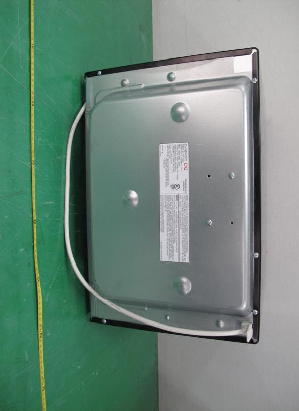
C5F7NF1CMO900N
Nov 23, 2014Microwave Oven
Equipment Class
8CC - Part 18 Consumer Device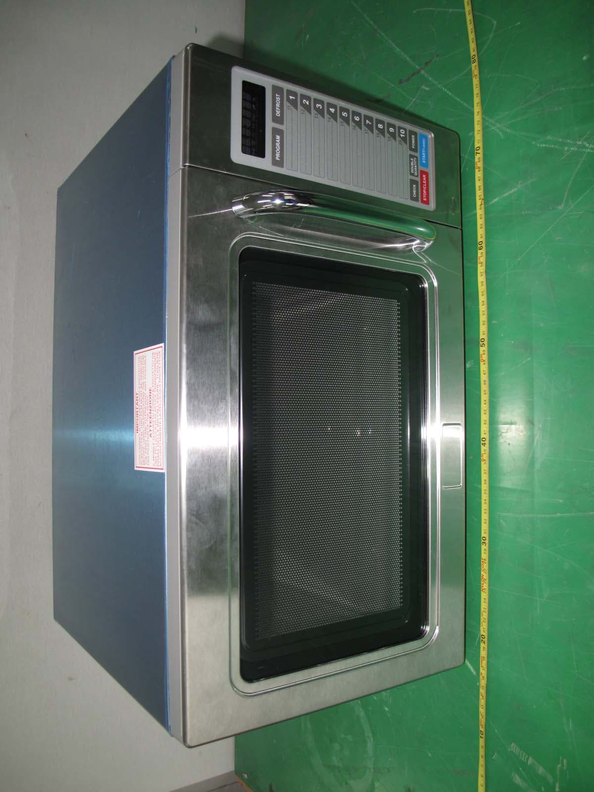
C5F7NF9PMO100N
Mar 25, 2013Commercial Microwave Oven
Equipment Class
8CC - Part 18 Consumer Device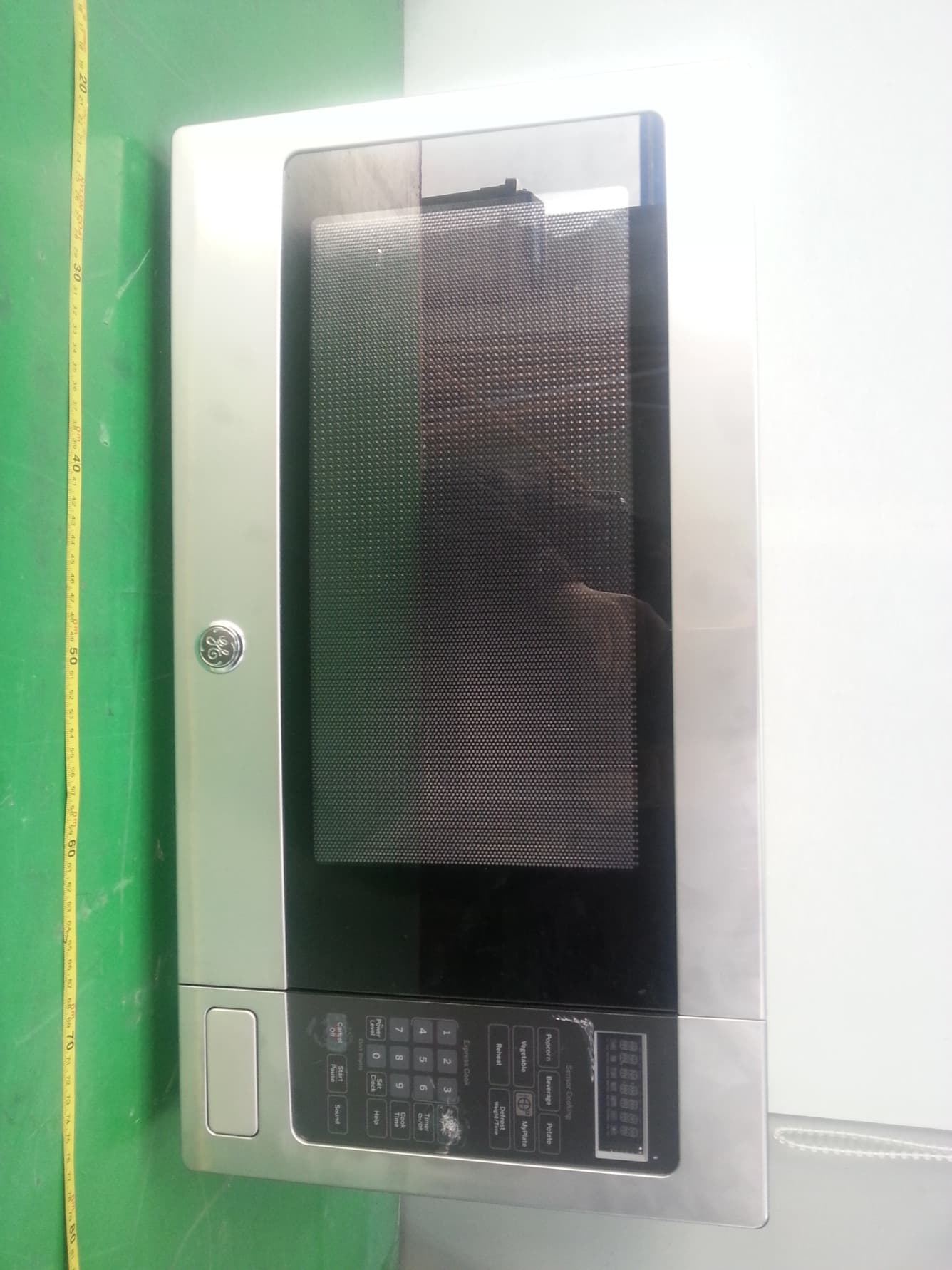
C5F7NF22MO110N
Jan 23, 2013Microwave Oven
Equipment Class
8CC - Part 18 Consumer Device
C5F7NF9FMO120N
May 06, 2012Commercial Microwave Oven
Equipment Class
8CC - Part 18 Consumer Device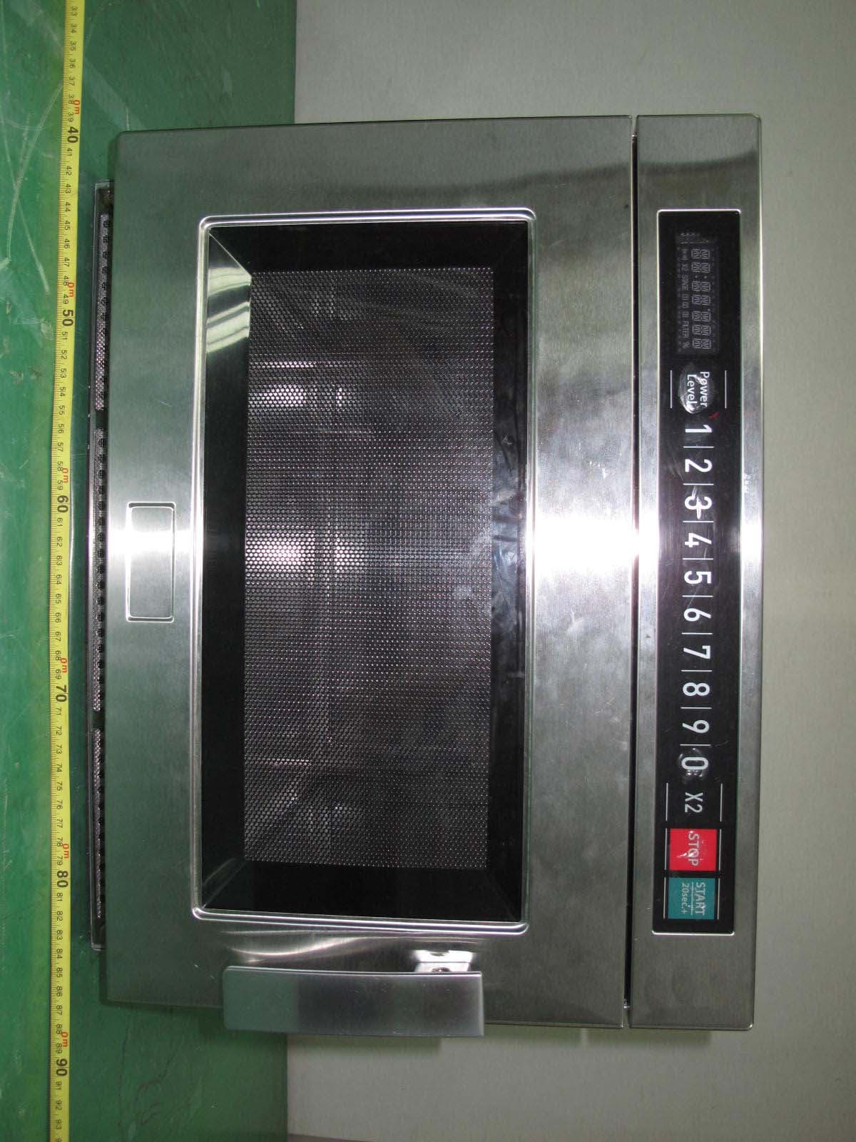
C5F7NF9FMO180N
Sep 05, 2011Commercial Microwave Oven
Equipment Class
8CC - Part 18 Consumer Device