C5FDLA37C737" LCD TV Monitor
WINIA Electronics Co., Ltd.
Click to zoom
Application Details
- Equipment Class
- JBP - Part 15 Class B Computing Device Peripheral
- Date of Grant
- Sep 17, 2007
- Application Purpose
- Original Equipment
- Date of Application
- Sep 17, 2007
- Equipment Note
- 37" LCD TV Monitor
- Company
- WINIA Electronics Co., Ltd.
- Country
- South Korea
Documents & Files
Document Text
Text extracted from the exhibit documents filed with the FCC. Open a document above to read the original.
Users Manual
Proper use guarantees product life. Before using the product, be advised that you read this owner’s manual well and try to operate it. INSTRUCTION MANUAL LCD TELEVISION C32HDGB C37HDGB C42HDGB WARNING : TO REDUCE THE RISK OF FIRE OR ELECTRIC SHOCK HAZARD, DO NOT EXPOSE THIS APPLIANCE TO RAIN OR MOISTURE. CAUTION : TO PREVENT ELECTRIC SHOCK, MATCH WIDE BLADE OF PLUG TO WIDE SLOT, FULLY INSERT. CAUTION RISK OF ELECTRIC SHOCK DO NOT OPEN CAUTION : TO REDUCE THE RISK OF ELECTRIC SHOCK, DO NOT REMOVE COVER (OR BACK). NO USER-SERVICEABLE PARTS INSIDE. REFER SERVICING TO QUALIFIED SERVICE PERSONNEL. The lightning flash with arrowhead symbol, within an equilateral triangle, is intended to alert the user to the presence of uninsulat- ed “dangerous voltage” within the product’s enclosure that may be of sufficient magnitude to constitute a risk electric shock. The exclamation point within an equilateral triangle is intended to alert the user to the presence of important operating and servic- ing instructions in the literature accompanying the appliance. Caution Caution 2 NOTE : This equipment has been tested and found to comply with the limits for a Class B digital device, pursuant to Part 15 of the FCC Rules. These limits are designed to provide reason- able protection against harmful interference in a residential installation. This equipment generates, uses and can radiate radio frequency energy and, if not installed and used in accordance with the instructions, may cause interference to radio communications. However, there is no guarantee that interference will not occur in a partic- ular installation. If this equipment does cause interference to radio or television reception which can be determined by turning the equipment off and on, the user is encouraged to try to correct the interference by one or more of the following measures. - Reorient or relocate the receiving antenna. - Increase the separation between the equipment and receiver. - Connect the equipment into an outlet on a circuit different from that to which the receiver is connected. - Consult authorized service centers for help. - Only shielded interface cable should be used. Finally, any changes or modifications to the equipment by the user not expressly approved by the grantee or manufacturer could void the users authority to operate such equipment, FCC RF IINTERFERENCE STATEMENT Important Safeguards 3 Please read the following safeguards for your TV and retain for future reference. Always follow all warnings and instructions marked on the television. 1. Read, Retain and Follow All Instructions Read all safety and operating instructions before operating the TV. Retain them safely for future reference. Follow all operations and instructions accordingly. 2. Heed Warnings Adhere to all warnings on the appliance and in the operating instructions. 3. Cleaning Unplug the TV from the wall outlet before cleaning. Do not use liquid, abrasive, or aerosol cleaners. Cleaners can permanently damage the cabinet and screen. Use a lightly dampened cloth for cleaning. 4. Attachments and Equipment Never add any attachment and/or equipment without approval of the manufacturer as such additions may result in the risk of fire, electric shock or other personal injury. 5. Water and Moisture The apparatus shall not be exposed to dripping or splashing and that no objects filled with liquids, such as vases, shall be placed on the apparatus. 6. Setting Do not place this TV on an unstable cart, stand or table. Placing the TV on an unstable base can cause the TV to fall, resulting in serious personal injuries as well as damage to the TV. Use only a cart, stand, bracket or table recommended by the manufacturer or salesperson. 7. Ventilation Slots and openings in the cabinet are provided for ventilation and to ensure reliable operation of the TV and to protect it from overheating. Do not cover the ventilations openings in the cabinet and never place the set in a confined space such as built-in cabinet unless proper ventilation is provided. Leave a minimum 10 cm gap all around the unit. 8. Power Source This TV should be operated only from the type of power source indicated on the marking label. If you are not sure of the type of power supplied to your home, consult your appliance dealer or local power company. 9. Grounding or Polarization This TV is equipped with a polarized alternating current line plug (a plug having one blade wider than the other). This plug will fit into the power outlet only one way. This is a safety feature. If you are unable to insert the plug fully into the outlet, try reversing the plug. If the plug should still fail to fit, contact your electrician to replace your obsolete outlet. Do not defeat the safety purpose of the polarized plug. A warning that an apparatus with CLASS I construction shall be connected to a MAINS socket outlet with a protective earthing connection. 10. Power-Cord Protection Power-supply cords should be routed so that they are not likely to be walked on or pinched by items placed upon or against them, paying particular attention to cords at plugs, wall outlets, and the point where they exit from the TV. MAINS plug is used as the disconnect device, the disconnect device shall remain readily operable. 11. Lightning For added protection for this TV during a lightning storm, or when it is left unattended and unused for long periods of time, unplug it from the wall outlet and disconnect the antenna or cable system. This will prevent damage to the TV due to lightning and power-line surges. Important Safeguards 4 13. Power Lines An outside antenna system should not be located in the vicinity of overhead power lines or other electric light or power circuits, or where it can fall into such power lines or circuits. When installing an outside antenna system, extreme care should be taken to keep from touching such power lines or circuits as contact with them might be fatal. 14. Overloading Do not overload wall outlets and exte…
Text truncated - open the document above for the full version.
Users Manual
Selection of Multimedia Input Signal 31 When connecting PC, STB, DVD with Multimedia 1. Pressing the "MULTIMEDIA" button on the remote controller. • Screen changes as follows whenever pressing the “MULTIMEDIA” button. Comp.1 => Comp.2 => HDMI => PC => Comp.1 Note: • If sound signal is mono method, connect it to the L-terminal of the sound input terminal. DISPLAY GUIDETV/VIDEOMULTIMEDIA POWER 123 456 PC Comp.1 Comp.2 HDMI Selection of Multimedia Input Signal 32 1. If the message ‘No signal’ appears on the screen, adjust the PC output to a format listed in the Multimedia Input table. Multimedia Input Format HDMI & PC mode Note : 1. When you connect with component, PC (D-Sub), and HDMI, you must check the input resolution of external devices. 2. So if this mode is used at PC mode, the screen can be enlarged. ResolutionV-freqHDMIPC(D-Sub)ComponentStandard 640 X 480 60HzOOXVESA Standard 75HzOOXVESA Standard 800 X 600 60HzOOXVESA Standard 75HzOOXVESA Standard 1024 X 768 60HzOOXVESA Standard 75HzOOXVESA Standard 1280 X 76860HzOOXVESA Standard 75HzOOXVESA Standard 1280 X 102460HzOOXVESA Standard 75HzOOXVESA Standard 720 X 480i60HzXXO 720 X 480p60HzOOO 1280 X 720p60HzOOO 1920 X 1080i60Hz OOO 1920 X 1080p60Hz OOO Picture Adjustment 33 Note : • 16:9:16:9 will display a true 16:9 (anamorphic) picture with no aspect distortions. • 4:3:General TV screen currently broadcasted. • LB(16:9) :Enlarge vertical size of the 16:9 picture. • LBS(16:9) :Move the LB(16:9) picture to the upper direction. • LB(16:9) and LBS(16:9) screen are not available in PC and HDMI mode. • "Screen Size" function is not available in PIP mode. Adjustment of Aspect ratio in TV/Video/Component mode 1. Press the "SCREEN SIZE" button • The screen changes as below whenever pressing the "SCREEN SIZE" button. 16:9 => 4:3 => LB[16:9] => LBS[16:9] => 16:9 16 : 9 MUTE SCREEN SIZE CAPTION PIP CHPIP CH PIP SWAP SOURCE POSITION SLEEP CH STILL ADD/ ERASE LB(16:9) LBS(16:9) 4 : 3 Picture Adjustment 34 Note. • You can adjust the PC menu only in the PC mode. • During the Auto Adjust, you must not alter a screen on the monitor. • During a moving picture, Auto Adjust is liable to incorrectly work. So you must execute Auto Adjust on a still image. • When Auto Adjust is not working correctly, you can adjust with H. Position, V. Position, Frequency and Phase. Adjustment of the screen in the PC mode 1. Select Picture by pressing the "Menu" button. • The menu screen appears as follows. 2. Select PC Screen Mode • Move to PC Screen Mode in the Picture menu by pressing the ” CH” buttons. • Press the ” VOL” button. Color temp PC Screen Mode Off N.R User Select 50 60 6 3. Select and adjust each items. • Move to item what you want by pressing the ” CH” button. • Adjust each items by pressing the ” VOL” button. Auto Set Phase H. Position V. Position PC Screen Mode Frequency Adjust 50 50 60 100 MENU FAV PREV.CH MUTE VOL VOL CH CH STILL Picture Adjustment 35 - The user may select various screens designed for a good picture without adjusting the brightness, contrast or color individually. Note. • Normal: For a highly defined image in a normally bright room • Dynamic: For a clear-cut image emphasizing high contrast for sports viewing • Cinema: Ideal for movies • User: Allows the user to customize settings as desired Color temp Off GR N.R Dynamic Adjust 43 80 60 10 Color temp Off GR N.R Cinema Adjust 50 60 50 6 Color temp Off GR N.R Adjust 45 70 55 8 Color temp Off GR N.R User Adjust 50 60 60 6 When setting up various screen modes 1. Picture Mode selects what you want. • Move to Mode in the Picture menu and Select desirable mode using the ” VOL” buttons. • Or press the “PICTURE MODE” button, then the screen status changes as followed: Normal => Dynamic => Cinema => User => Normal • The screen adjustment status changes as the following screens are displayed sequentially whenever pressing the “PICTURE MODE” button. • The screen returns to the mode prior to turning power off when then turning power on again. CC SWAP P.MODE S.MODES.EFFECT MTS SOURCE POSITION Picture Adjustment 36 - You can enjoy various screens by adjusting Brightness, Contrast, Color, Sharpness, etc to the user’s taste. - Through color temperature control, you can change the tone of color Color temp Off GR N.R Select 45 70 55 8 Color temp Off GR N.R Adjust 45 70 55 8 When adjusting the screen to taste 1. Select Picture by pressing the “Menu” button. • The menu screen appears as follows. 2. Select and adjust each items. • Move to the PICTURE menu. • Whenever pressing the ” CH” button, you can select in order of Brightness, Contrast, Color, Tint, Sharpness and Noise Reduction. • You can adjust all items by pressing the ” VOL” buttons Note: • Brightness : Adjust the whole of screen brighter or darker. • Contrast : Adjust difference between brightness and darkness between objects and background on the screen. • Color : Adjust color thinly or thickly. • Tint : Adjust the natural tint of the image. • Sharpness : Adjust outline of the screen smoothly or sharply. • N . R : Reduce the noise in the picture due to poor reception or poor picture quality (Only IN TV (Analog mode) and AV1/2 mode). Note: • Tint actives when receiving a NTSC signal. • The adjusted levels are stored automatically in User mode. 1. Move to the Color Temp. menu with ” CH” buttons. • Using the ” VOL” buttons, select the desired Color Temperature. Note: • Normal : Normal White • Warm : Reddish white • Cool : Bluish white Adjustment of Color Temperature in TV Sound Adjustment 37 When selecting various sound Effects 1. Sound mode selects what you want. • Move to Effect in the Sound menu. • Select desirable Effect using the ” VOL” buttons. • Or press the “S.EFFECT” button, then the sound status changes as followed: Off => Voice Effect => Dynamic Bass => Off Adjust Equalizer On Off Normal Speaker BBE Adjust Equalizer On Off Normal Speaker Off Adjust Equalizer On Off Normal Speaker M. Voice Note. • Voice Effect : Allows human voice to be heard …
Text truncated - open the document above for the full version.
Block Diagram
From PW338 To PW338 To MSP From MSP From PWM2030 S5H1409(SS) VSB/QAM Demodulator AGC PWM2030(Pixelworks) MPEG DECODER PW338(Pixelworks) SCALER L/R Component HDMI PC Monitor Out SPDIF Output (Optical) LCD PANEL LVDS HDMI SIF Sound L/R TS 8bit HDMI VIDEO1, Y1/C1, VIDEO2, Y2/C2 Y1/Y2 Pb1/Pb2 Pr1/Pr2 Y1/Pb1/Pr1, Y2/Pb2/Pr2 PC(RGBHV) EDID EEPROM I2C HDMI_PC L/R Component1 L/R FT-232 TX0 RX0 UART0 TX UART0 RX PC(RGBHV) CVBS 4052 (MUX) SPDIF_HDMI SPDIF_DTV SPDIF_MSP SPDIF_MSP SPDIF_HDMI SPDIF_DTV CVBS CVBS I2S HDMI_PC L/R Component1 L/R Component2 L/R Video/S-Video1 L/R Video/S-Video2 L/R I2S NOR Flash 32Mbit DDR RAM X 2 (128Mb X 2) EEPROM Digital Video Out(16bit) PIC16F690 U-COM Component2 L/R I2C I2C I2C To PW338 Local Bus I2C From HDMI IR I2S PSU On / Vs On LED Control NAND Flash 256Mbit 32bit 32bit CLK, SYNC, VALID 8bit 16bit 16bit 16bit PCLK1, PHS1, PVS1, PCLK2, PHS2, PVS2 DDR RAM X 2 (256Mb X 2) DISPEN, SDA, SCL To Monitor Out I2S I2S To PW338 I2S IF TUNER I2C I2C I2C SBOEn, SBWEn, PWCEn SPDIF_S/W PIC CTRL En VIDEO/ S-VIDEO 1 Video1, Y1/C1 Video/S-Video1 L/R VIDEO/ S-VIDEO 2 Video2, Y2/C2 Video/S-Video2 L/R POWER KEY ISCPCLK ISCPDAT MCLR Up-grade SBACK MSP RESET SIF CVBS TDVS-H702D LG ATSC/NTSC TUNER
ID Label/Location Info
ID Label Sample Location Information ID Label Sample Location Information
Test Report
IST Co., Ltd EMC LABORATORY TEST REPORT NO. : 07-IST-0366 1 of 16 Certification of Compliance CFR 47 Part 15 Subpart B Test Report File No. : 07-IST-0366 Date of Issue : September 12, 2007 Model(s) : DLA-37C7, C37HDGB Kind of Product : 37” LCD TV MONITOR FCC ID : C5FDLA37C7 Applicant : Daewoo Electronics Corporation. Address : 543, Dangjung-Dong, Kunpo-City, Kyounggi-DO, Korea Manufacturer : Daewoo Electronics Corporation. Address : 295, Kongdan-dong, Kumi-city, Kyungsangbuk-do, Korea. Test Result ■ Positive □ Negative Reviewed By Approved By Comment(s) - Investigations requested : Measurement to the relevant clauses of FCC rules and regulations Part 15 Subpart B – Unintentional Radiators, Class B. - The test report with appendix consists of 16 pages. - The test result only responds to the tested sample. - It is not allowed to copy this report even partly without the allowance of IST EMC Laboratory. - This equipment as for has been shown to be capable of continued compliance with the applicable technical standards as indicated in the measurement report and was tested in accordance with the measurement procedures specified in ANSI C63.4 2003. S.J.Cho / EMC Group Manager J.H.Lee / Chief IST Co., Ltd EMC LABORATORY TEST REPORT NO. : 07-IST-0366 2 of 16 TABLE OF CONTENTS Table of contents 2 Information of test laboratory, Environmental conditions, Power used, Product information 3 Descriptions of test Conducted Emission 4 Radiated Emission 5 Equipment Under Test 6 Summary 7 ■ Test Conditions and Data - Emissions ◆ Conducted Emissions 0.15MHz - 30MHz Applicable Test Conditions / Data and Plots 8-10 ◆ Radiated Emissions 30MHz - 1GHz Applicable Test Conditions / Data and Plots 11-12 ■ Appendix A. The Photos of Test Setup 13-14 B. The Photos of Equipment Under Test 15-16 Note: IST Co., Ltd EMC LABORATORY TEST REPORT NO. : 07-IST-0366 3 of 16 INFORMATIONS OF TEST LABORATORY EMC LABORATORY of IST Co., Ltd. (FCC Filing Lab.) 400-19, Singal-Dong, Giheung-Gu, Yongin-Si, Gyeonggi-Do, 446-599, Korea TEL : +82 31 326 6700 FAX : +82 31 326 6797 ENVIRONMENTAL CONDITIONS Temperature 28 °C Humidity 54 % Atmospheric pressure 1013 mbar POWER SUPPLY SYSTEM USED Power supply system 120 Vac, 60 Hz (Refer to the product information) PRODUCT INFORMATION Power Source 120 V~, 60 Hz Power Consumption 150 W Screen Size 37” Aspect Ratio 16 : 9 Resolution 1366 x 768 (WXGA) Pixel Pitch 0.200 x 0.600 mm x RGB Contrast Ratio 3000 : 1 Set Dimension (W x H x D) 940 x 720 x 328.5 mm TV System NTSC, ATSC - EMC suppression device is not used during the test . - Please refer to user’s manual. IST Co., Ltd EMC LABORATORY TEST REPORT NO. : 07-IST-0366 4 of 16 < Concept Drawing > 215 >150 >40 80 Receiver DUT LISN 80 ≥ 80 80 40 ≥ 80 Measuring apparatus Mains Filter Mains Rear side Equipment under test Coaxial cable Artificial mains networ k Screened room Non-metallic support 80 DESCRIPTIONS OF TEST Conducted Emissions: The measurement were performed over the frequency range of 0.15 MHz to 30 MHz using a 50 Ω /50 uH LISN as the input transducer to a Spectrum Analyzer or a Field Intensity Meter. The measurements were made with the detector set for "Peak" amplitude within a bandwidth of 10 KHz or for "quasi-peak" & “Average” within a bandwidth of 9 KHz. - Procedure of Test The line-conducted facility is located inside a shielded room No.1. A 1 m X 1.5 m wooden table 80cm height is placed 40 cm away from the vertical wall and 1.5 m away from the other wall of the shielded room. The Hyup-Rip KNW-407 and EMCO 3725/2 LISN are bonded to bottom of the shielded room. The EUT is located on the wooden table with distance more than 80 cm from the LISN and powered from the EMCO LISN .The peripheral equipment is powered from the other LISN. Power to the LISNs are filtered by a noise cut power line filters. All electrical cables are shielded by braided tinned steel tubing with inner φ 1.2 cm. If the EUT is a DC-powered device, power will be derived from the source power supply it normally will be powered from and this supply lines will be connected to the EMCO LISN. All interconnecting cables more than 1m were shortened by non-inductive bundling to a 1m length. Sufficient time for the EUT, support equipment, and test equipment was allowed in order for them to warm up to their normal operating conditions. The RF output of the LISN was connected to the R/S receiver to determine the frequency producing the maximum emission from the EUT. The frequency producing the maximum level was reexamined using Quasi-Peak mode by manual measurement, after scanned by automatic Peak mode for frequency range from 0.15 to 30 MHz. The bandwidth of the receiver was set to 10 kHz. The EUT, peripheral equipment, and interconnecting cables were arranged and manipulated to maximize each EME emission. < Side View > IST Co., Ltd EMC LABORATORY TEST REPORT NO. : 07-IST-0366 5 of 16 DESCRIPTION OF TEST Radiated Emissions: The measurement was performed over the frequency range of 30 MHz to 1 GHz using antenna as the input transducer to a Spectrum analyzer or a Field Intensity Meter. The measurement was made with the detector set for "quasi-peak" within a bandwidth of 120 KHz. - Procedure of Test Preliminary measurements were made at 3 meter using bi-conical and log-periodic antennas, and spectrum analyzer to determine the frequency producing the max. emission in anechoic chamber. Appropriate precaution was taken to ensure that all emission from the EUT were maximized and investigated. The system configuration, mode of operation, turn-table azimuth and height with respect to the antenna were noted for each frequency found. The spectrum was scanned from 30 MHz to 1000 MHz using S/B bi-log antenna. Above 1GHz, linearly polarized double ridge horn antennas were used. Final measurements were made at open site with 3-meters test distance using S/B bi-log antenna or horn antenna. The OATS have been verified in regular for its normalized site attenuation. The test equipment was placed o…
Text truncated - open the document above for the full version.
Contact Information
Applicant
Youjin Choi(Manager)
Technical Contact
IST Co., Ltd.Jae-Ho Park
[email protected]82-31-326-6750
400-19, Singal-dong, Giheung-gu, Yongin-si, · Yongin-Si · South Korea
Non-Technical Contact
IST Co., Ltd.Jae-Ho Park
[email protected]82-31-326-6750
Test Firm
IST Co., Ltd.Jae-Ho Park
Technical Specifications
| # | Rule Parts | Frequency Range | Power Output |
|---|---|---|---|
| 1 | 15B | - | - |
Other Applications from WINIA Electronics Co., Ltd.
C5F7NF1CMO900N
Nov 23, 2014Microwave Oven
Equipment Class
8CC - Part 18 Consumer Device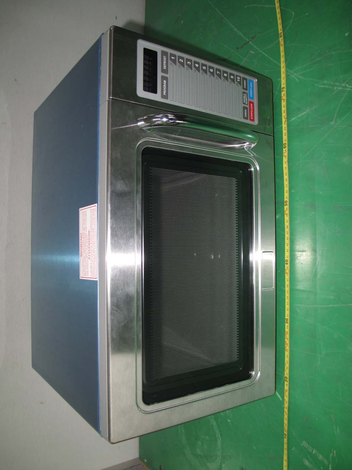
C5F7NF9PMO100N
Mar 25, 2013Commercial Microwave Oven
Equipment Class
8CC - Part 18 Consumer Device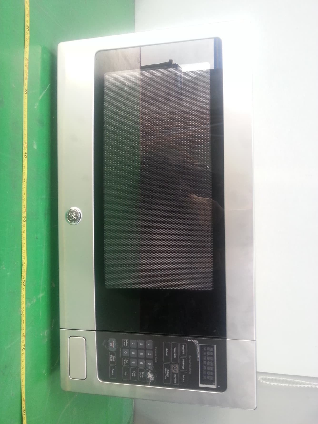
C5F7NF22MO110N
Jan 23, 2013Microwave Oven
Equipment Class
8CC - Part 18 Consumer Device
C5F7NF9FMO120N
May 06, 2012Commercial Microwave Oven
Equipment Class
8CC - Part 18 Consumer Device
C5F7NF9FMO180N
Sep 05, 2011Commercial Microwave Oven
Equipment Class
8CC - Part 18 Consumer Device