C9O-QOLL2Qollector Activity Monitor
SRAM LLC.Application Details
- Equipment Class
- PCB - PCS Licensed Transmitter
- Date of Grant
- Nov 24, 2015
- Application Purpose
- Original Equipment
- Date of Application
- Nov 04, 2015
- Equipment Note
- Qollector Activity Monitor
- Frequency Range
- 1852.40000000 - 1907.60000000
- Company
- SRAM LLC.
- Country
- United States
Documents & Files
Document Text
Text extracted from the exhibit documents filed with the FCC. Open a document above to read the original.
Users Manual
Q Button Cellular Status GPS Status Battery Statuss Power Meter Indicator Charging Port Heart Rate Indicator Other Ant+ Indicator Qollector To pair the Qollector with a sensor, press and release the and hold the Qollector near the sensor. The corresponding white icon will light up when the sensor is paired. Up to 7 sensors can be paired with the Qollector. Press the to check the Cellular Status, Battery Status, and GPS Status. The will blink often when on and connected. Double tap the front surface of the device to drop a pin and record a specific point in your activity. You can view the pin in your autosync destinations. The Qollector will collect and store data when it is first turned on, but you will need to create an account on QuarqNet.com to view, download and sync your data. To Start or Finish an Activity: Power the Qollector on and allow the cellular towers and GPS to sync before starting your activity. When you have finished your activity, power the Qollector off. Your activity will automatically be named and synced up with your autosync destinations. Using the Qollector For complete instructions, visit our website at quarq.com/qollector. Press and hold the for three seconds to power the Qollector on or off. When powering on, the status icons will light up green and the Qollector will beep and vibrate. When powering off, the icons will flash red and the Qollector will beep and vibrate. Front Surfaces Commands Press Press - 3 Sec Double Tap Qollector Quick Start Guide Data collection and tracking for endurance athletes. Solid Light: Connected to a tower - Data synced Two second fade: Connected to a tower - Data unsynced One second fade: No tower found Solid Light: GPS locked Two second fade: GPS searching One second fade: GPS disabled Solid Light: Battery Status Good: 100% - 35% Two second fade: Battery Status Low: 35% - 10% One second fade: Battery Status Critical: 10% or less Power Meter Paired Heart Rate Monitor Paired Ant+ Device Paired Color Definitions DRAFT For complete instructions, visit our website at quarq.com/qollector.
RF Exposure Info
Plot No. 1 Test Laboratory: UL Verification Services Inc., SAR Lab 1 Date/Time: 8/10/2015 8:08:32 PM 20150810 SystemPerformanceCheck-D835V2 SN 4d142 Frequency: 835 MHz; Duty Cycle: 1:1; Room Ambient Temperature: 24.0°C; Liquid Temperature: 23.0°C Medium parameters used: f = 835 MHz; σ = 1.016 S/m; ε r = 52.738; ρ = 1000 kg/m 3 DASY5 Configuration: - Area Scan Setting: Find Secondary Maximum Within: 2.0 dB and with a peak SAR value greater than 0.0012W/kg - Electronics: DAE4 Sn1352; Calibrated: 11/7/2014 - Probe: EX3DV4 - SN7356; ConvF(9.97, 9.97, 9.97); Calibrated: 4/22/2015; - Sensor-Surface: 2.5mm (Mechanical Surface Detection) - Phantom: ELI-A v5.0; Type: QDOVA002AA; Serial: TP 1194 Body/Pin=100 mW/Area Scan (7x7x1): Measurement grid: dx=15mm, dy=15mm Maximum value of SAR (measured) = 0.946 W/kg Body/Pin=100 mW/Zoom Scan (7x7x7)/Cube 0: Measurement grid: dx=5mm, dy=5mm, dz=5mm Reference Value = 30.825 V/m; Power Drift = 0.07 dB Peak SAR (extrapolated) = 1.28 W/kg SAR(1 g) = 0.864 W/kg; SAR(10 g) = 0.571 W/kg Maximum value of SAR (measured) = 1.05 W/kg 0 dB = 1.05 W/kg = 0.21 dBW/kg Plot No. 2 Test Laboratory: UL Verification Services Inc., SAR Lab 1 Date/Time: 8/10/2015 8:27:46 PM 20150810 SystemPerformanceCheck-D835V2 SN 4d142 Frequency: 835 MHz; Duty Cycle: 1:1 Body/Pin=100 mW/Z Scan (1x1x21): Measurement grid: dx=20mm, dy=20mm, dz=5mm Maximum value of SAR (measured) = 0.950 W/kg Plot No. 3 Test Laboratory: UL Verification Services Inc., SAR Lab 2 Date/Time: 8/11/2015 6:36:03 PM 20150811_SystemPerformanceCheck-D1750V2 SN 1050 Frequency: 1750 MHz; Duty Cycle: 1:1; Room Ambient Temperature: 24.0°C; Liquid Temperature: 23.0°C Medium parameters used: f = 1750 MHz; σ = 1.476 S/m; ε r = 52.02; ρ = 1000 kg/m 3 DASY5 Configuration: - Area Scan Setting: Find Secondary Maximum Within: 2.0 dB and with a peak SAR value greater than 0.0012W/kg - Electronics: DAE4 Sn1259; Calibrated: 1/14/2015 - Probe: EX3DV4 - SN3990; ConvF(8.08, 8.08, 8.08); Calibrated: 3/18/2015; - Sensor-Surface: 2.5mm (Mechanical Surface Detection) - Phantom: ELI A v5.0; Type: QDOVA002AA; Serial: S/n:1198 Body/Pin=100 mW/Area Scan (7x7x1): Measurement grid: dx=15mm, dy=15mm Maximum value of SAR (measured) = 4.89 W/kg Body/Pin=100 mW/Zoom Scan (7x7x7)/Cube 0: Measurement grid: dx=5mm, dy=5mm, dz=5mm Reference Value = 58.524 V/m; Power Drift = -0.03 dB Peak SAR (extrapolated) = 6.95 W/kg SAR(1 g) = 3.89 W/kg; SAR(10 g) = 2.07 W/kg Maximum value of SAR (measured) = 5.23 W/kg 0 dB = 5.23 W/kg = 7.19 dBW/kg Plot No. 4 Test Laboratory: UL Verification Services Inc., SAR Lab 2 Date/Time: 8/11/2015 6:57:57 PM 20150811_SystemPerformanceCheck-D1750V2 SN 1050 Frequency: 1750 MHz; Duty Cycle: 1:1 Body/Pin=100 mW/Z Scan (1x1x21): Measurement grid: dx=20mm, dy=20mm, dz=5mm Maximum value of SAR (measured) = 4.87 W/kg Plot No. 5 Test Laboratory: UL Verification Services Inc., SAR Lab 2 Date/Time: 8/28/2015 2:04:15 PM 20150828 SystemPerformanceCheck-D1750V2 SN 1053 Frequency: 1750 MHz; Duty Cycle: 1:1; Room Ambient Temperature: 24.0°C; Liquid Temperature: 23.0°C Medium parameters used: f = 1750 MHz; σ = 1.502 S/m; ε r = 51.801; ρ = 1000 kg/m 3 DASY5 Configuration: - Area Scan Setting: Find Secondary Maximum Within: 2.0 dB and with a peak SAR value greater than 0.0012W/kg - Electronics: DAE4 Sn1259; Calibrated: 1/14/2015 - Probe: EX3DV4 - SN3990; ConvF(8.08, 8.08, 8.08); Calibrated: 3/18/2015; - Sensor-Surface: 2.5mm (Mechanical Surface Detection) - Phantom: ELI A v5.0; Type: QDOVA002AA; Serial: S/n:1198 Body/Pin=100 mW/Area Scan (7x7x1): Measurement grid: dx=15mm, dy=15mm Maximum value of SAR (measured) = 4.95 W/kg Body/Pin=100 mW/Zoom Scan (7x7x7)/Cube 0: Measurement grid: dx=5mm, dy=5mm, dz=5mm Reference Value = 58.162 V/m; Power Drift = 0.01 dB Peak SAR (extrapolated) = 6.97 W/kg SAR(1 g) = 3.9 W/kg; SAR(10 g) = 2.08 W/kg Maximum value of SAR (measured) = 5.23 W/kg 0 dB = 5.23 W/kg = 7.19 dBW/kg Plot No. 6 Test Laboratory: UL Verification Services Inc., SAR Lab 2 Date/Time: 8/28/2015 2:26:17 PM 20150828 SystemPerformanceCheck-D1750V2 SN 1053 Frequency: 1750 MHz; Duty Cycle: 1:1 Body/Pin=100 mW/Z Scan (1x1x21): Measurement grid: dx=20mm, dy=20mm, dz=5mm Maximum value of SAR (measured) = 4.92 W/kg Plot No. 7 Test Laboratory: UL Verification Services Inc., SAR Lab 3 Date/Time: 8/11/2015 11:28:57 AM 20150811_SystemPerformanceCheck-D1900V2 SN 5d163 Frequency: 1900 MHz; Duty Cycle: 1:1; Room Ambient Temperature: 24.0°C; Liquid Temperature: 23.0°C Medium parameters used: f = 1900 MHz; σ = 1.52 S/m; ε r = 52.018; ρ = 1000 kg/m 3 DASY5 Configuration: - Area Scan Setting: Find Secondary Maximum Within: 2.0 dB and with a peak SAR value greater than 0.0012W/kg - Electronics: DAE4 Sn1434; Calibrated: 4/16/2015 - Probe: EX3DV4 - SN3749; ConvF(7.09, 7.09, 7.09); Calibrated: 1/26/2015; - Sensor-Surface: 2.5mm (Mechanical Surface Detection) - Phantom: ELI-B v5.0; Type: QDOVA001BB; Serial: 1215 Body/Pin=100 mW/Area Scan (7x7x1): Measurement grid: dx=15mm, dy=15mm Maximum value of SAR (measured) = 5.60 W/kg Body/Pin=100 mW/Zoom Scan (7x7x7)/Cube 0: Measurement grid: dx=5mm, dy=5mm, dz=5mm Reference Value = 61.18 V/m; Power Drift = 0.06 dB Peak SAR (extrapolated) = 7.75 W/kg SAR(1 g) = 4.19 W/kg; SAR(10 g) = 2.18 W/kg Maximum value of SAR (measured) = 5.65 W/kg 0 dB = 5.65 W/kg = 7.52 dBW/kg Plot No. 8 Test Laboratory: UL Verification Services Inc., SAR Lab 3 Date/Time: 8/11/2015 11:46:21 AM 20150811_SystemPerformanceCheck-D1900V2 SN 5d163 Frequency: 1900 MHz; Duty Cycle: 1:1 Body/Pin=100 mW/Z Scan (1x1x21): Measurement grid: dx=20mm, dy=20mm, dz=5mm Maximum value of SAR (measured) = 5.66 W/kg Plot No. 9 Test Laboratory: UL Verification Services Inc., SAR Lab 5 Date/Time: 9/1/2015 12:04:13 PM 20150901_SystemPerformanceCheck-D835V2 SN 4d142 Frequency: 835 MHz; Duty Cycle: 1:1; Room Ambient Temperature: 24.0°C; Liquid Temperature: 23.0°C Medium parameters used: f = 835 MHz; σ = 1.008 S/m; ε r = 53.639; ρ = 1000 kg/m 3 DASY5 Configuration: - Area Scan Setting: …
Text truncated - open the document above for the full version.
RF Exposure Info
Plot No. 1 Test Laboratory: UL Verification Services Inc., SAR Lab 5 Date/Time: 9/1/2015 8:44:09 PM GSM 850 Frequency: 824.4 MHz; Duty Cycle: 1:4.00037; Room Ambient Temperature: 24.0°C; Liquid Temperature: 23.0°C Medium parameters used: f = 825 MHz; σ = 0.999 S/m; ε r = 53.773; ρ = 1000 kg/m 3 DASY5 Configuration: - Area Scan Setting: Find Secondary Maximum Within: 2.0 dB and with a peak SAR value greater than 0.0012W/kg - Electronics: DAE4 Sn1239; Calibrated: 4/16/2015 - Probe: EX3DV4 - SN3773; ConvF(8.26, 8.26, 8.26); Calibrated: 4/22/2015; - Sensor-Surface: 2.5mm (Mechanical Surface Detection (Locations From Previous Scan Used)), Sensor-Surface: 2.5mm (Mechanical Surface Detection) - Phantom: ELI v5.0 (A); Type: QDOVA001BB; Serial: 1213 Rear/GPRS 2 slots_ch 128/Area Scan (8x10x1): Measurement grid: dx=15mm, dy=15mm Maximum value of SAR (measured) = 3.43 W/kg Rear/GPRS 2 slots_ch 128/Zoom Scan (6x7x7)/Cube 0: Measurement grid: dx=8mm, dy=8mm, dz=5mm Reference Value = 61.79 V/m; Power Drift = -0.01 dB Peak SAR (extrapolated) = 5.01 W/kg SAR(1 g) = 3.27 W/kg; SAR(10 g) = 2.28 W/kg Maximum value of SAR (measured) = 3.91 W/kg 0 dB = 3.91 W/kg = 5.92 dBW/kg Plot No. 2 Test Laboratory: UL Verification Services Inc. SAR Lab F Date/Time: 11/3/2015 2:23:13 PM GSM 850 Frequency: 836.6 MHz; Duty Cycle: 1:4.00037; Room Ambient Temperature: 24.0°C; Liquid Temperature: 23.0°C Medium parameters used (interpolated): f = 836.6 MHz; σ = 1.015 S/m; ε r = 53.164; ρ = 1000 kg/m 3 DASY5 Configuration: - Area Scan Setting: Find Secondary Maximum Within: 2.0 dB and with a peak SAR value greater than 0.0012W/kg - Electronics: DAE4 Sn1359; Calibrated: 2/18/2015 - Probe: EX3DV4 - SN3929; ConvF(8.57, 8.57, 8.57); Calibrated: 4/22/2015; - Sensor-Surface: 2.5mm (Mechanical Surface Detection) - Phantom: ELI v5.0 (B); Type: QDOVA001BB; Serial: 1118 Front/GPRS 2 slots_ch 190/Area Scan (8x10x1): Measurement grid: dx=15mm, dy=15mm Info: Interpolated medium parameters used for SAR evaluation. Maximum value of SAR (measured) = 1.79 W/kg Front/GPRS 2 slots_ch 190/Zoom Scan (5x5x7)/Cube 0: Measurement grid: dx=8mm, dy=8mm, dz=5mm Reference Value = 42.917 V/m; Power Drift = -0.01 dB Peak SAR (extrapolated) = 2.03 W/kg SAR(1 g) = 1.62 W/kg; SAR(10 g) = 1.17 W/kg Info: Interpolated medium parameters used for SAR evaluation. Maximum value of SAR (measured) = 1.82 W/kg 0 dB = 1.82 W/kg = 2.60 dBW/kg Plot No. 3 Test Laboratory: UL Verification Services Inc. SAR Lab E Date/Time: 11/19/2015 8:33:32 AM GSM 850 Frequency: 836.6 MHz; Duty Cycle: 1:4.00037; Room Ambient Temperature: 24.0°C; Liquid Temperature: 23.0°C Medium parameters used (interpolated): f = 836.6 MHz; σ = 0.984 S/m; ε r = 53.563; ρ = 1000 kg/m 3 DASY5 Configuration: - Area Scan Setting: Find Secondary Maximum Within: 2.0 dB and with a peak SAR value greater than 0.0012W/kg - Electronics: DAE4 Sn1439; Calibrated: 7/30/2015 - Probe: EX3DV4 - SN3772; ConvF(8.46, 8.46, 8.46); Calibrated: 2/23/2015; - Sensor-Surface: 2.5mm (Mechanical Surface Detection) - Phantom: ELI v5.0 B; Type: QDOVA002AA; Serial: 1180 Edge 2/GPRS 2 slots_ch 190/Area Scan (8x11x1): Measurement grid: dx=15mm, dy=15mm Info: Interpolated medium parameters used for SAR evaluation. Maximum value of SAR (measured) = 1.87 W/kg Edge 2/GPRS 2 slots_ch 190/Zoom Scan (5x5x7)/Cube 0: Measurement grid: dx=8mm, dy=8mm, dz=5mm Reference Value = 44.161 V/m; Power Drift = 0.04 dB Peak SAR (extrapolated) = 2.50 W/kg SAR(1 g) = 1.71 W/kg; SAR(10 g) = 1.13 W/kg Info: Interpolated medium parameters used for SAR evaluation. Maximum value of SAR (measured) = 2.06 W/kg 0 dB = 2.06 W/kg = 3.14 dBW/kg Plot No. 4 Test Laboratory: UL Verification Services Inc. SAR Lab E Date/Time: 11/19/2015 10:42:30 AM GSM 850 Frequency: 836.6 MHz; Duty Cycle: 1:4.00037; Room Ambient Temperature: 24.0°C; Liquid Temperature: 23.0°C Medium parameters used (interpolated): f = 836.6 MHz; σ = 0.984 S/m; ε r = 53.563; ρ = 1000 kg/m 3 DASY5 Configuration: - Area Scan Setting: Find Secondary Maximum Within: 2.0 dB and with a peak SAR value greater than 0.0012W/kg - Electronics: DAE4 Sn1439; Calibrated: 7/30/2015 - Probe: EX3DV4 - SN3772; ConvF(8.46, 8.46, 8.46); Calibrated: 2/23/2015; - Sensor-Surface: 2.5mm (Mechanical Surface Detection) - Phantom: ELI v5.0 B; Type: QDOVA002AA; Serial: 1180 Edge 3/GPRS 2 slots_ch 190/Area Scan (7x9x1): Measurement grid: dx=15mm, dy=15mm Info: Interpolated medium parameters used for SAR evaluation. Maximum value of SAR (measured) = 0.513 W/kg Edge 3/GPRS 2 slots_ch 190/Zoom Scan (5x5x7)/Cube 0: Measurement grid: dx=8mm, dy=8mm, dz=5mm Reference Value = 23.071 V/m; Power Drift = -0.09 dB Peak SAR (extrapolated) = 0.859 W/kg SAR(1 g) = 0.420 W/kg; SAR(10 g) = 0.223 W/kg Info: Interpolated medium parameters used for SAR evaluation. Maximum value of SAR (measured) = 0.574 W/kg 0 dB = 0.574 W/kg = -2.41 dBW/kg Plot No. 5 Test Laboratory: UL Verification Services Inc. SAR Lab E Date/Time: 11/19/2015 9:09:21 AM GSM 850 Frequency: 824.4 MHz; Duty Cycle: 1:4.00037; Room Ambient Temperature: 24.0°C; Liquid Temperature: 23.0°C Medium parameters used: f = 825 MHz; σ = 0.974 S/m; ε r = 53.657; ρ = 1000 kg/m 3 DASY5 Configuration: - Area Scan Setting: Find Secondary Maximum Within: 2.0 dB and with a peak SAR value greater than 0.0012W/kg - Electronics: DAE4 Sn1439; Calibrated: 7/30/2015 - Probe: EX3DV4 - SN3772; ConvF(8.46, 8.46, 8.46); Calibrated: 2/23/2015; - Sensor-Surface: 2.5mm (Mechanical Surface Detection (Locations From Previous Scan Used)), Sensor-Surface: 2.5mm (Mechanical Surface Detection) - Phantom: ELI v5.0 B; Type: QDOVA002AA; Serial: 1180 Edge 4/GPRS 2 slots_ch 128/Area Scan (8x11x1): Measurement grid: dx=15mm, dy=15mm Maximum value of SAR (measured) = 2.37 W/kg Edge 4/GPRS 2 slots_ch 128/Zoom Scan (5x5x7)/Cube 0: Measurement grid: dx=8mm, dy=8mm, dz=5mm Reference Value = 49.662 V/m; Power Drift = 0.05 dB Peak SAR (extrapolated) = 3.09 W/kg SAR(1 g) = 2.12 W/kg; SAR(10 g) = 1.42 W/kg Maximum value of SAR (measured) …
Text truncated - open the document above for the full version.
RF Exposure Info
NVLAP LAB CODE 200065-0 SAR EVALUATION REPORT FCC 47 CFR § 2.1093 IEEE Std 1528-2013 For GERAN/UMTS/2.4 GHz Qollector Activity Monitor FCC ID: C9O-QOLL2 Model Name: QOLLECTOR2 Report Number: 15U21180-S1V4 Issue Date: 11/19/2015 Prepared for SRAM LLC 1000 W Fulton Market, 4th Floor Chicago, IL, 60607 United States Prepared by UL VERIFICATION SERVICES INC. 47173 BENICIA STREET FREMONT, CA 94538, U.S.A. TEL: (510) 771-1000 FAX: (510) 661-0888 Report No.: 15U21180-S1V4 Issue Date: 11/19/2015 Page 2 of 29 UL Verification Services Inc. Doc. No.: 1.0 This report shall not be reproduced without the written approval of UL Verification Services Inc. Revision History Rev. Date Revisions Revised By V1 9/15/2015 Initial Issue -- V2 11/2/2015 1. Duty Cycle updated 2. Section 7 updated 3. FCC ID updated 4. Added ANT+ Lance Fleischer V3 11/4/2015 1. Added data for Front Test Position 2. Updated Appendices A/B/C/E/F to V2 3. Section 12: Added Simultaneous Analysis Coltyce Sanders V4 11/19/2015 1. Added data for Edges 2/3/4 Test Positions 2. Updated Appendices A/B/C/E/F to V3 Coltyce Sanders Report No.: 15U21180-S1V4 Issue Date: 11/19/2015 Page 3 of 29 UL Verification Services Inc. Doc. No.: 1.0 This report shall not be reproduced without the written approval of UL Verification Services Inc. Table of Contents 1. Attestation of Test Results ......................................................................................................... 5 2. Test Specification, Methods and Procedures ............................................................................ 6 3. Facilities and Accreditation ........................................................................................................ 6 4. SAR Measurement System & Test Equipment .......................................................................... 7 4.1. SAR Measurement System ........................................................................................................ 7 4.2. SAR Scan Procedures ............................................................................................................... 8 4.3. Test Equipment ........................................................................................................................ 10 5. Measurement Uncertainty ......................................................................................................... 12 6. Device Under Test (DUT) Information ...................................................................................... 13 6.1. DUT Description ...................................................................................................................... 13 6.2. Wireless Technologies ............................................................................................................. 13 6.3. Testing Rationale ..................................................................................................................... 13 6.4. Nominal and Maximum Output Power ...................................................................................... 14 7. RF Exposure Conditions (Test Configurations) ...................................................................... 14 8. Dielectric Property Measurements & System Check .............................................................. 15 8.1. Dielectric Property Measurements ........................................................................................... 15 8.2. System Check.......................................................................................................................... 18 9. Conducted Output Power Measurements ................................................................................ 21 9.1. GSM ........................................................................................................................................ 21 9.2. W-CDMA ................................................................................................................................. 22 9.3. ANT+ ....................................................................................................................................... 22 10. Measured and Reported (Scaled) SAR Results ....................................................................... 23 10.1. GSM850 ............................................................................................................................... 24 10.2. GSM1900 ............................................................................................................................. 24 10.3. W-CDMA Band II .................................................................................................................. 24 10.4. W-CDMA Band IV ................................................................................................................ 24 10.5. W-CDMA Band V ................................................................................................................. 25 10.6. ANT+ .................................................................................................................................... 25 11. SAR Measurement Variability ................................................................................................... 26 12. Simultaneous Transmission SAR Analysis ............................................................................. 27 12.1. Sum of the SAR for GSM850 & ANT+ .................................................................................. 27 12.2. Sum of the SAR for GSM1900 & ANT+ ................................................................................ 27 Report No.: 15U21180-S1V4 Issue Date: 11/19/2015 Page 4 of 29 UL Verification Services Inc. Doc. No.: 1.0 This report shall not be reproduced without the written approval of UL Verification Services Inc. 12.3. Sum of the SAR for W-CDMA Band II & ANT+ ..................................................................... 27 12.4. Sum of the SAR for W-CDMA Band IV & AN…
Text truncated - open the document above for the full version.
Test Report
FCC CFR47 PART 24 SUBPART E FCC CFR47 PART 22 SUBPART H FCC CFR47 PART 27 SUBPART L INDUSTRY CANADA RSS-132 ISSUE 3 INDUSTRY CANADA RSS-133 ISSUE 6 INDUSTRY CANADA RSS-139 ISSUE 3 CERTIFICATION TEST REPORT GSM/WCDMA & ANT+ MODEL NUMBER: QOLLECTOR2 FCC ID: C9O-QOLL2 IC ID: 10161A-QOLL2 REPORT NUMBER: 15U21180-E2V3 ISSUE DATE: NOVEMBER 03, 2015 Prepared for SRAM LLC 1000 W Fulton Market, 4th Floor Chicago, IL, 60607 United States Prepared by UL VERIFICATION SERVICES INC. 47173 BENICIA STREET FREMONT, CA 94538, U.S.A. TEL: (510) 771-1000 FAX: (510) 661-0888 REPORT NO: 15I21237-E2V3 DATE: NOVEMBER 03, 2015 FCC ID: C9O-QOLL2 IC ID: 10161A-QOLL2 Page 2 of 28 UL VERIFICATION SERVICES INC. FORM NO: CCSUP4701H 47173 BENICIA STREET, FREMONT, CA 94538, USA TEL: (510) 771-1000 FAX: (510) 661-0888 This report shall not be reproduced except in full, without the written approval of UL Verification Services Inc. Revision History Rev. Issue Date Revisions Revised By V1 10/20/15 Initial Issue ( This report contain spot check test data of Qollector2) C.OOI V2 10/22/15 Add full radiated testing result to test report. C.OOI V3 11/03/15 Revised Page 7 C.OOI REPORT NO: 15I21237-E2V3 DATE: NOVEMBER 03, 2015 FCC ID: C9O-QOLL2 IC ID: 10161A-QOLL2 Page 3 of 28 UL VERIFICATION SERVICES INC. FORM NO: CCSUP4701H 47173 BENICIA STREET, FREMONT, CA 94538, USA TEL: (510) 771-1000 FAX: (510) 661-0888 This report shall not be reproduced except in full, without the written approval of UL Verification Services Inc. TABLE OF CONTENTS 1. ATTESTATION OF TEST RESULTS ............................................................................. 4 2. TEST METHODOLOGY ................................................................................................. 5 3. FACILITIES AND ACCREDITATION ............................................................................. 5 4. CALIBRATION AND UNCERTAINTY ............................................................................ 6 4.1. MEASURING INSTRUMENT CALIBRATION .............................................................. 6 4.2. SAMPLE CALCULATION ............................................................................................ 6 4.3. MEASUREMENT UNCERTAINTY ............................................................................... 6 5. EQUIPMENT UNDER TEST .......................................................................................... 7 5.1. DESCRIPTION OF EUT .............................................................................................. 7 5.2. MAXIMUM OUTPUT POWER...................................................................................... 7 5.3. DESCRIPTION OF AVAILABLE ANTENNAS .............................................................. 7 5.4. DESCRIPTION OF TEST SETUP ................................................................................ 8 6. TEST AND MEASUREMENT EQUIPMENT ..................................................................10 7. RADIATED TEST RESULTS ........................................................................................11 7.1. RADIATED POWER (ERP & EIRP) ............................................................................11 7.1.1. ERP/EIRP Results ...............................................................................................13 7.2. FIELD STRENGTH OF SPURIOUS RADIATION........................................................20 7.2.1. SPURIOUS RADIATION PLOTS .........................................................................21 8. SETUP PHOTOS ..........................................................................................................28 REPORT NO: 15I21237-E2V3 DATE: NOVEMBER 03, 2015 FCC ID: C9O-QOLL2 IC ID: 10161A-QOLL2 Page 4 of 28 UL VERIFICATION SERVICES INC. FORM NO: CCSUP4701H 47173 BENICIA STREET, FREMONT, CA 94538, USA TEL: (510) 771-1000 FAX: (510) 661-0888 This report shall not be reproduced except in full, without the written approval of UL Verification Services Inc. 1. ATTESTATION OF TEST RESULTS COMPANY NAME: SRAM LLC EUT DESCRIPTION: GERAN/UMTS/2.4 GHz MODEL: QOLLECTOR2 SERIAL NUMBER: LX-00052510 DATE TESTED: OCTOBER 22, 2015 APPLICABLE STANDARDS STANDARD TEST RESULTS FCC PART 22H, 24E, 27L PASS UL Verification Services Inc. tested the above equipment in accordance with the requirements set forth in the above standards. All indications of Pass/Fail in this report are opinions expressed by UL Verification Services Inc. based on interpretations and/or observations of test results. Measurement Uncertainties were not taken into account and are published for informational purposes only. The test results show that the equipment tested is capable of demonstrating compliance with the requirements as documented in this report. Note: The results documented in this report apply only to the tested sample, under the conditions and modes of operation as described herein. This document may not be altered or revised in any way unless done so by UL Verification Services Inc. and all revisions are duly noted in the revisions section. Any alteration of this document not carried out by UL Verification Services Inc. will constitute fraud and shall nullify the document. This report must not be used by the client to claim product certification, approval, or endorsement by NVLAP, NIST, any agency of the Federal Government, or any agency of any government. Approved & Released For UL Verification Services Inc. By: Tested By: CHOON OOI ANGEL ESCAMILLA CONSUMER TECHNOLOGY DIVISION CONSUMER TECHNOLOGY DIVISION PROJECT LEAD LAB ENGINEER UL VERIFICATION SERVICES INC UL VERIFICATION SERVICES INC REPORT NO: 15I21237-E2V3 DATE: NOVEMBER 03, 2015 FCC ID: C9O-QOLL2 IC ID: 10161A-QOLL2 Page 5 of 28 UL VERIFICATION SERVICES INC. FORM NO: CCSUP4701H 47173 BENICIA STREET, FREMONT, CA 94538, USA TEL: (510) 771-1000 FAX: (510) 661-0888 This report shall not be reproduced except in full, without the written approval of UL Verification Services Inc. 2. TEST…
Text truncated - open the document above for the full version.
Test Setup Photos
REPORT NO: 15I21237-E2V3 DATE: NOVEMBER 03, 2015 FCC ID: C9O-QOLL2 IC ID: 10161A-QOLL2 Page 28 of 28 UL VERIFICATION SERVICES INC. FORM NO: CCSUP4701H 47173 BENICIA STREET, FREMONT, CA 94538, USA TEL: (510) 771-1000 FAX: (510) 661-0888 This report shall not be reproduced except in full, without the written approval of UL Verification Services Inc. 8. SETUP PHOTOS RADIATED PHOTO (BELOW 1 GHz) RADIATED PHOTO (Above 1 GHz) END OF REPORT
Test Setup Photos
Report No.: 15U21180-S1V3 DUT and SAR Set-up Photos Overall Dimensions 55.6 mm 98.9 mm 101.4 mm Report No.: 15U21180-S1V3 Front View of the DUT Rear View of the DUT Report No.: 15U21180-S1V3 Setup Photos Handset Vertical and Horizontal Reference Lines Vertical Center Line Horizontal Line Report No.: 15U21180-S1V3 Body-worn Exposure Conditions Rear Front Report No.: 15U21180-S1V3 Edge 2 Edge 3 Report No.: 15U21180-S1V3 Edge 4 Report No.: 15U21180-S1V3 Antenna Dimensions & Separation Distances
Contact Information
Applicant
Leo Yermakov(Product Compliance Manager)
Test Firm
UL Verification Services Inc. (formerly UL CCS)Jay Kogoma
Technical Specifications
| # | Rule Parts | Frequency Range | Power Output | Emission | Tolerance |
|---|---|---|---|---|---|
| 7 | 24E | 1.85 GHz - 1.91 GHz | 179.00 mW | 4M10F9W | 2.5 ppm |
Other Applications from SRAM LLC.
C9O-SLMB2
Jun 17, 2026Electronic Controller
Equipment Class
DTS - Digital Transmission System
C9O-SPMB2
Jan 11, 2024ELECTRONIC CONTROLLER WITH BLE AND AIREA RADIOS
Equipment Class
DTS - Digital Transmission System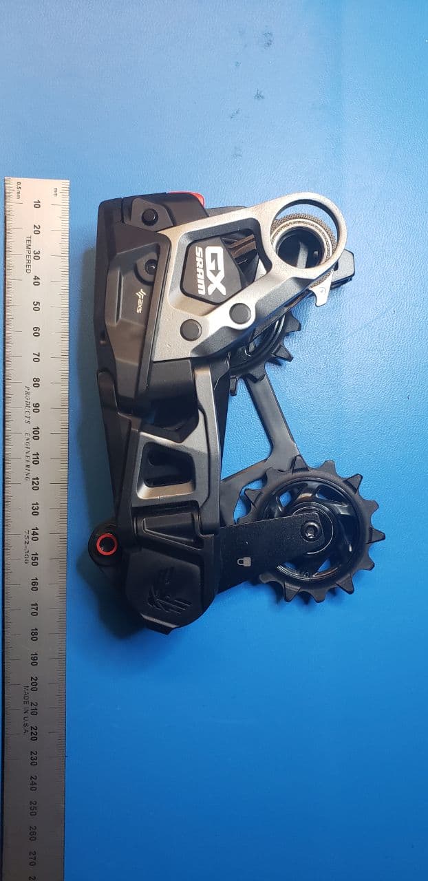
C9O-RDMB2
Jan 31, 2023Rear Derailleur with BLE, AIREA and ANT+ Radios
Equipment Class
DXX - Part 15 Low Power Communication Device Transmitter
C9O-HMIMB1
Jan 31, 2023Bridge Display
Equipment Class
DXX - Part 15 Low Power Communication Device Transmitter
C9O-BLPB2
May 22, 2021Wireless Blip with BLE and AIREA Radios
Equipment Class
DTS - Digital Transmission System