CH87500XX-07Versalink Wifi Device
Westell Inc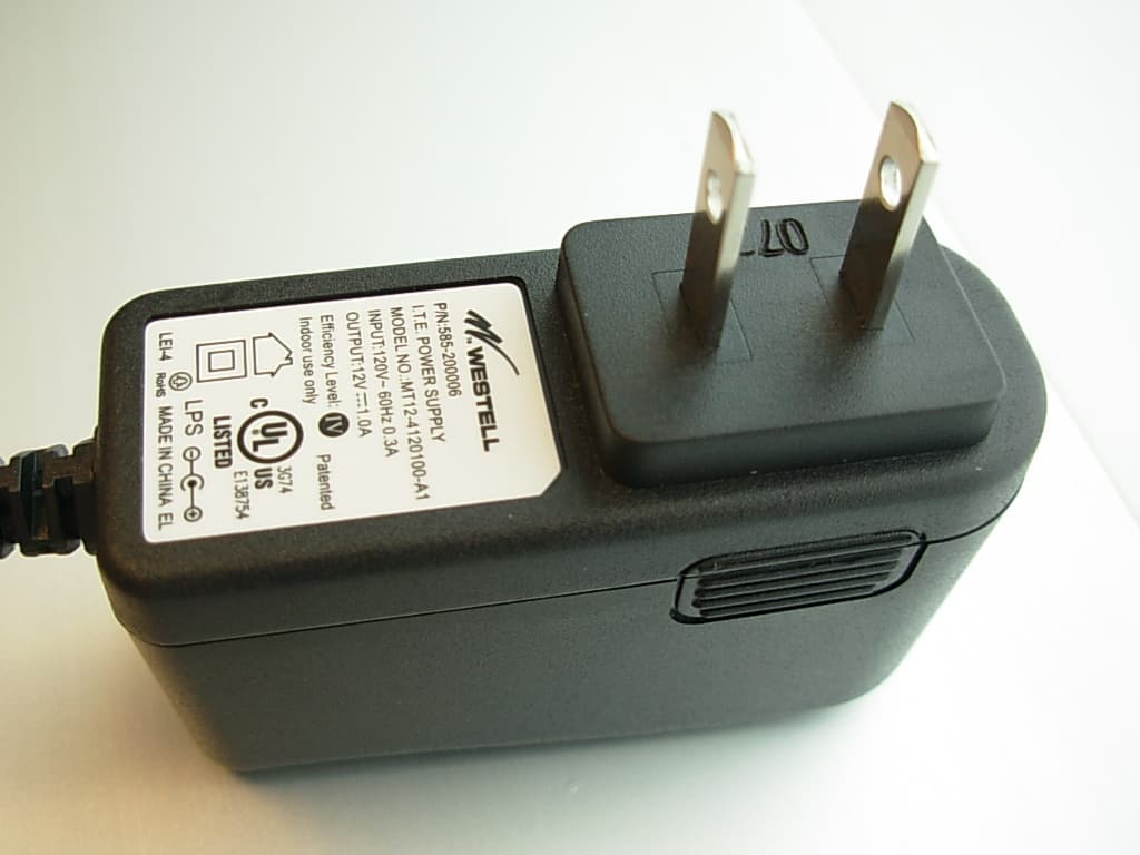
Click to zoom
Application Details
- Equipment Class
- DTS - Digital Transmission System
- Date of Grant
- Dec 20, 2007
- Application Purpose
- Original Equipment
- Date of Application
- Dec 19, 2007
- Equipment Note
- Versalink Wifi Device
- Frequency Range
- 2412.00000000 - 2462.00000000
- Company
- Westell Inc
- Country
- United States
Documents & Files
Document Text
Text extracted from the exhibit documents filed with the FCC. Open a document above to read the original.
Users Manual
030-300536 Rev. A 1 August 2007 VERSALINK™ WIRELESS GATEWAY (MODEL 7500) USER GUIDE 030-300536 Rev. A 2 August 2007 User GuideVersaLink Wireless Gateway (Model 7500) CONTENTS 1. PRODUCT DESCRIPTION ..................................................................................................................................5 2. SAFETY INSTRUCTIONS ...................................................................................................................................5 3. REGULATORY INFORMATION ........................................................................................................................6 3.1 FCC Compliance Note ...............................................................................................................................6 3.2 Canada Certification Notice.......................................................................................................................7 4. NETWORKING REQUIREMENTS .....................................................................................................................8 5. HARDWARE FEATURES....................................................................................................................................9 5.1 LED Indicators...........................................................................................................................................9 5.2 Cable Connectors and Switch Locations..................................................................................................10 5.3 Connector Descriptions............................................................................................................................10 5.4 Installation Requirements ........................................................................................................................11 5.5 Before you begin......................................................................................................................................11 5.6 Microfilters ..............................................................................................................................................11 6. HARDWARE INSTALLATIONS.......................................................................................................................12 7. INSTALLING THE USB DRIVERS...................................................................................................................17 7.1 Installing the USB Driver for Windows 98 SE ........................................................................................17 7.2 Installing the USB Driver for Windows ME............................................................................................23 7.3 Installing the USB Driver for Windows 2000..........................................................................................25 7.4 Installing the USB Driver for Windows XP.............................................................................................28 7.5 Installing the USB Driver for Windows Vista™ .....................................................................................30 8. ACCESSING VERSALINK ................................................................................................................................31 8.1 Logging on to VersaLink .........................................................................................................................31 8.2 Changing the Password............................................................................................................................32 9. CONFIGURING YOUR BROADBAND CONNECTION .................................................................................35 9.1 Confirming Your DSL Connection ..........................................................................................................35 9.2 Setting Up an Account Profile .................................................................................................................36 9.3 Connecting to the Internet........................................................................................................................41 9.4 Disconnecting from the Internet...............................................................................................................42 10. SETTING UP MACINTOSH OS X.....................................................................................................................44 10.1 Opening the System Preference Screen ...................................................................................................44 10.2 Choosing the Network Preferences ..........................................................................................................44 10.3 Creating a New Location .........................................................................................................................45 10.4 Naming the New Location .......................................................................................................................45 10.5 Selecting the Ethernet Configuration .......................................................................................................45 10.6 Checking the IP Connection ....................................................................................................................46 10.7 Accessing Your Router ............................................................................................................................47 11. BASIC CONFIGURATION ................................................................................................................................48 030-300536 Rev. A 3 August 2007 User GuideVersaLink Wireless Gateway (Model 7500) 12. MAIN (HOME PAGE).........................................................................................................................................49 12.1 My Gateway Panel ....................................................…
Text truncated - open the document above for the full version.
Users Manual
030-300536 Rev. A 126 August 2007 User GuideVersaLink Wireless Gateway (Model 7500) 15.6 Static NAT In the Firewall Settings screen, select Static NAT from the submenu options displayed at the left of the screen. A warning screen will display the following message: Any changes made in this section may affect your device’s performance and configuration. Do you want to proceed? Click Yes to proceed. 15.6.1 Enabling Static NAT If you clicked Yes in the warning screen, the following Static NAT screen will appear. The Static NAT screen allows you to configure your Router to work with the special NAT services. When the Router is configured for Static NAT, any unsolicited packets arriving at the WAN will be forwarded to the selected device. This feature can be used when you want to host a server for a specific application. IMPORTANT: Static NAT and DMZ Host are mutually exclusive features. Before you enable static NAT, confirm that DMZ Host is disabled. If needed, refer to section 15.4.2 for details on disabling DMZ Host. 030-300536 Rev. A 127 August 2007 User GuideVersaLink Wireless Gateway (Model 7500) To enable Static NAT, select a device from the Static NAT Device drop-down menu, or enter the IP address of the device to which you want to assign Static NAT. Next, click Enable. The following screen shows that Static NAT has been enabled for the device you selected. 030-300536 Rev. A 128 August 2007 User GuideVersaLink Wireless Gateway (Model 7500) 15.6.2 Disabling Static NAT To disable Static NAT (if it has been previously enabled), click Disable in the Static NAT screen. After you have disabled Static NAT the following screen will show no devices enabled for static NAT. 030-300536 Rev. A 129 August 2007 User GuideVersaLink Wireless Gateway (Model 7500) 15.7 Security Log In the Firewall Settings screen, select Security Log from the submenu options displayed at the left of the screen. A warning screen will display the following message: Any changes made in this section may affect your device’s performance and configuration. Do you want to proceed? Click Yes to proceed. If you clicked Yes in the warning screen, the following Security Log screen will appear. This screen alerts you of noteworthy information sent to VersaLink from the Internet. The screen can contain 1000 entries, but a maximum of 50 entries are displayed at a time. Once 1000 entries have been logged, the oldest entry is removed to make space for the new entries as they occur. 030-300536 Rev. A 130 August 2007 User GuideVersaLink Wireless Gateway (Model 7500) Security Log Close Clicking this button closes the security log screen. Clear log Clicking this button removes all entries from the log. Settings Clicking this button opens a new window that contains configuration settings for selecting the information that you want logged. Printable/savable format Clicking this button opens a new window that contains a list of all the logged packets that can be saved or printed. You can send a copy of the Firewall log to a designated printer. Refresh Clicking this button updates the screen so that it displays the most current data. Time Displays the time that the packet was sent. Direction/Source Displays the direction of transmission. Rule/Reason Displays the internal rule that caused the logged event. The internal rule is set up under Firewall rules. Alert Displays a description of the logged event. Details Displays details about logged event. If you clicked Settings in the preceding Security Log screen, the following Firewall Log Settings screen will appear. This screen allows you to configure firewall remote logging. Remote logging allows the firewall logs to be sent to a machine running a syslog server. NOTE: The syslog server must be configured to isten on udp port 514, which is usually the default port. In order for the logs to be saved to the syslog server, the server should be configured to save the logs to a file. Some of the free syslog servers available on the Internet are kiwisyslog, MT_syslog and 3Csyslog. To configure Remote Logging, do the following: 1. Select the desired firewall log settings from the drop-down menus. 2. Click the Enable check box below Remote Logging (a check mark will appear in the box). 3. Type the IP address of the syslog server in the Remote IP Address field. 4. Click Apply to allow the settings to take effect. 030-300536 Rev. A 131 August 2007 User GuideVersaLink Wireless Gateway (Model 7500) 16. ADVANCED The following sections discuss the advanced features of your Router, such as IP address distribution, firmware upgrades, etc. IMPORTANT: This section assumes that you have active DSL and Internet service. If you select Advanced in the top navigational menu, a warning screen will display the following message: Any changes made in this section may affect your device’s performance and configuration. Do you want to proceed? Click Yes to proceed. 030-300536 Rev. A 132 August 2007 User GuideVersaLink Wireless Gateway (Model 7500) If you clicked Yes in the preceding warning screen, the following screen will appear. The Advanced screen allows you to access various configurable features in your Router. To access a feature, click the link of the feature that you want to access. The features shown in this page will be discussed in the following sections. 16.1 Diagnostics In the Advanced screen, click Diagnostics. The following screen will appear. Using this screen, you can run the following diagnostics tests: • To run a DNS test, type the appropriate host name in the field provided, and then click test. • To run a PING test, type the appropriate IP address or host name in the field provided, and then click test. • To run a Trace Route, type the appropriate IP address or host name in the field provided, and then click trace. • To run a full diagnostic test on your Router, click Test All. 030-300536 Rev. A 133 August 2007 User GuideVersaLink Wireless Gateway (Model 7500) If you want to PING using the System Self T…
Text truncated - open the document above for the full version.
Users Manual
030-300536 Rev. A 68 August 2007 User GuideVersaLink Wireless Gateway (Model 7500) 13.4.4 802.11b/g Mode If you select the 802.11b/g Mode link in the Advanced Security Settings screen, the following screen will be displayed. This screen allows you to limit access to your Router based on technology type. From the drop-down menu, select the desired setting. Then, click Apply to allow the settings to take effect. 11b only: Communication with VersaLink is limited to 802.11b 11g only: Communication with VersaLink is limited to 802.11g Legacy Mixed: Communication with VersaLink is limited to 802.11b/g 802.11b/g Mode Mixed mode: Computers using 802.11b or 802.11g technology can communicate with VersaLink. 030-300536 Rev. A 69 August 2007 User GuideVersaLink Wireless Gateway (Model 7500) 13.4.5 Other Advanced Wireless Options If you select the Other Advanced Wireless Options link in the Advanced Security Settings screen, the following screen will appear. From the drop-down menus, select the desired settings. Then, click Apply to allow the settings to take effect. Wireless Advanced Configuration Beacon Interval The time interval between beacon frame transmissions. Beacons contain rate and capability information. Beacons received by stations can be used to identify the access points in the area. DTIM Interval The number of Beacon intervals between DTIM transmissions. Multicast and broadcast frames are delivered after every DTIM Fragmentation Threshold Any MSDU or MPDU larger than this value will be fragmented into an MPDU of the specified size. RTS Threshold RTS/CTS handshaking will be performed for any data or management MPDU containing a number of bytes greater than the threshold. If this value is larger than the MSDU size (typically set by the fragmentation threshold), no handshaking will be performed. A value of zero will enable handshaking for all MPDUs. Supported Rates (Mbps) 802.11b Rates (Mbps) 802.11g Rates (Mbps) These are the allowable communication rates that VersaLink will attempt to use. The rates are also broadcast within the connection protocol as the rates supported by VersaLink. 030-300536 Rev. A 70 August 2007 User GuideVersaLink Wireless Gateway (Model 7500) 14. MY NETWORK This section discusses details about your Router’s network. 14.1 Network Status To view your Router’s network settings, from the top navigational menu, select My Network. Next, click Network Status in the submenu at the left of the screen. The following screen will appear. This screen displays information about the devices connected to your local area network (LAN). My Network Type The type of device connected to your network Status The connection status for the device. Connection Type The physical connection used to interface with your Router. IP Address The IP address assigned to your computer. IP Address Source The method by which your computer receives its IP address. MAC Address The Media Access Controller; the hardware address assigned to the deviced by the manufacturer. Connected Devices The interfaces used to connect to your Router to the computer. Ethernet: Displays the number of devices that are connected to the Router via Ethernet 10/100 BaseT connection. Wireless: Displays the number of devices that are connected to the Router wirelessly. USB: Displays the number of devices that are connected to the Router via USB connection. Note: If you have computers on your network that are not being displayed, check the firewall setting on the PCs to ensure that the firewall is disabled. 030-300536 Rev. A 71 August 2007 User GuideVersaLink Wireless Gateway (Model 7500) 14.1.1 Access Shared Files In the My Network panel, click the Access Shared Files link to access files from a device on your local network. (The device from which you will access files must have file sharing enabled.) If the device has a firewall turned on, you will not be able to access shared files from the device. 14.1.2 View Device Details In the My Network panel, click the View Device Details link to view details about your device. After you have finished viewing this screen, click Close to return to the My Network page. 030-300536 Rev. A 72 August 2007 User GuideVersaLink Wireless Gateway (Model 7500) 14.1.3 Rename Device In the My Network panel, click the Rename Device link to rename a device on your network. In the following screen, type the desired name in the New Name box, and then (if desired) select an icon from the New Icon drop- down menu to assign a different icon to this device. Next, click the Rename Device button to allow the changes to take effect. Click Back to return to the My Network panel. 14.1.4 Delete Device In the My Network panel, click the Delete Device link to remove a device from your network. Click the Clear button next to the device that you want to remove from your network, or click Clear All to remove all devices from your network. 030-300536 Rev. A 73 August 2007 User GuideVersaLink Wireless Gateway (Model 7500) 14.1.5 Enable Application In the My Network panel, click the Enable Application link to set up applications for your service profile. This feature enables applications (Games, Webcams, IM & Others) by opening a tunnel between remote (Internet) computers and a specific device port inside your local area network (LAN). Details on this screen will be discussed later in section 15.3, “Port Forwarding.” 030-300536 Rev. A 74 August 2007 User GuideVersaLink Wireless Gateway (Model 7500) 14.2 Network Connections To edit your connection settings, from the top navigational menu select My Network. Next, select Network Connections in the submenu options at the left of the screen; the following screen will be displayed. This screen allows you to access your Router’s connection settings and your local area network (LAN) settings. The following sections discuss the details of this screen. • To access the Router’s Broadband connection settings, in the Network Connections screen click the Broadband Connection (DSL) lin…
Text truncated - open the document above for the full version.
Users Manual
030-300536 Rev. A 108 August 2007 User GuideVersaLink Wireless Gateway (Model 7500) If you clicked Add, the following screen will be displayed. Click Create. If you clicked Create, the following Create Port Forwarding Service screen will appear. Using this screen, you can create port forwarding and port triggering services for your Router. The following sections explain how to customize these services in your Router. • Port Forwarding Ranges of Ports: This option allows you to forward a range of WAN ports to an IP address on the LAN. • Trigger Ports: This option allows you to forward a range of ports to an IP address on the LAN only after specific outbound traffic. 030-300536 Rev. A 109 August 2007 User GuideVersaLink Wireless Gateway (Model 7500) 15.3.3.3.1 Creating a Service Based on Specific Port Forwarding Ports The Port Forwarding feature allows you to forward a range of WAN ports to an IP address on the LAN. You can set up a port forwarding entry based on your specific ports. IMPORTANT: Using various Internet applications depends on the Router’s firewall settings. Make sure that the Router’s firewall is set to Medium Security or lower to take advantage of all the port forwarding features. Firewall settings take precedence over port forwarding services configured in the Router. For example, if the firewall is set to Medium Security, this will block ICMP packets even if the ICMP service is enabled. If a port forwarding service is not working, try setting the firewall to a lower setting. To create a port forwarding service based on specific port forwarding ports, at the Create Port Forwarding Service screen, do the following: 1. Type the name of the custom service that you are creating in the field provided. This will be the name of the port forwarding service for which you are configuring specific Port Forwarding rules. 2. Click the Port Forwarding option. 3. Select the desired protocol from the Protocol drop-down menu. 4. Enter the desired Global Port Start, Global Port End, and Base Host Port values in the fields provided, as shown in the example below. 5. Select the desired direction settings 6. Click Apply to allow the changes to take effect. NOTE: If you clicked Cancel in the Create Port Forwarding Service screen, the service you created will be displayed; however, it will not be activated in your Router. You must click Apply to allow the settings to take effect. 030-300536 Rev. A 110 August 2007 User GuideVersaLink Wireless Gateway (Model 7500) Port Forwarding Service Protocol TCP – Transmission Control Protocol UDP – User Datagram Protocol Global Port Start The WAN-side TCP/UDP start port. Global Port End The WAN-side TCP/UDP end port. Base Host Port The port on the WAN that will host the port forwarding service selected. Base Host Port is the first port that will be used for a specific service when configured for a range of ports. Direction/ Port Directon The port direction for the port forwarding rule. If you clicked Apply, the following Service Details screen will be displayed. Click Done. 7. Return to the New Port Forwarding Rule screen and, from the drop-down menu, select the name of the custom service that you created (the name should appear at the bottom of the list under Custom Defined Service). 030-300536 Rev. A 111 August 2007 User GuideVersaLink Wireless Gateway (Model 7500) This screen displays the service name in the field. 8. Select how the service will be activated. • Host allows unsolicited inbound traffic to a particular PC on the LAN. • Dynamic enables inbound traffic based on specific outbound traffic. 9. Select the IP address of the device that will host the service (select a device from the Select a Discovered LAN device drop-down menu or type an IP address in the field provided). 10. Click Apply to allow the service to be added to the Router’s list of active services. 030-300536 Rev. A 112 August 2007 User GuideVersaLink Wireless Gateway (Model 7500) If you clicked Apply, the following screen will appear. The Port Forwarding service has been added to the list of active services. To add additional port forwarding services to your Router, repeat steps 1 through 10. To view the details for the service, click the details icon in the Action field. The following screen will appear. Click Close to return to the Port Forwarding screen. 030-300536 Rev. A 113 August 2007 User GuideVersaLink Wireless Gateway (Model 7500) 15.3.3.3.2 Creating a Service Based on Specific Port Triggering Ports The Trigger Ports feature allows you to forward a range of ports to an IP address on the LAN only after specific outbound traffic. You can set up a port triggering entry based on your specific ports. IMPORTANT: Using various Internet applications depends on the Router’s firewall settings. Make sure that the Router’s firewall is set to Medium Security or lower to take advantage of all the port forwarding features. Firewall settings take precedence over port forwarding services configured in the Router. For example, if the firewall is set to Medium Security, this will block ICMP packets even if the ICMP service is enabled. If a port forwarding service is not working, try setting the firewall to a lower setting. To create a port forwarding service based on specific port triggering ports, at the New Port Forwarding Rule screen, click Create. 030-300536 Rev. A 114 August 2007 User GuideVersaLink Wireless Gateway (Model 7500) If you clicked Create in the preceding screen, the following screen will appear. Complete the following steps to add a port triggering rule. 1. Click the Port Triggering option. (By factory default, the Port Forwarding option will be selected.) If you clicked the Port Triggering option in the preceding screen, the following Create Port Triggering Rule screen will be displayed. 030-300536 Rev. A 115 August 2007 User GuideVersaLink Wireless Gateway (Model 7500) 2. Type the name of the custom service that you are creating in the field provided. This will be the name o…
Text truncated - open the document above for the full version.
Cover Letter(s)
THE EMC COMPLIANCE CENTER 12 East Devonwood SOLVING A WAVE OF EMI COMPLIANCE PROBLEMS Romeoville, IL 60446 December 14, 2007 Tel: (815) 293-0772 Page 1 of 1 Fax: (815) 293-0820 Federal Communications Commission RP- Authorization and Evaluation Division 7435 Oakland Mills Rd. Columbia, MD 21046 Fax 301-344-2050 Reference FCC ID: CH87500XX-07 Organization: Westell Inc. Subject: Confidentiality Request regarding application for certification of FCC ID: CH87500XX-07 In accordance with Sections 0.457 and 0.459 of the Commission’s Rules, Westell hereby requests Permanent confidential treatment of information accompanying this application as outlined below: • Schematics • Block Diagrams The above materials contain proprietary and confidential information not customarily released to the public. The public disclosure of these materials provides unjustified benefits to its competitors in the market. Authorized Signature Joseph Strzelecki Senior EMC Engineer Radiometrics Midwest Corporation Authorized Agent for Westell, Inc.
Cover Letter(s)
THE EMC COMPLIANCE CENTER 12 East Devonwood SOLVING A WAVE OF EMI COMPLIANCE PROBLEMS Romeoville, IL 60446 December 14, 2007 Tel: (815) 293-0772 Page 1 of 1 Fax: (815) 293-0820 Federal Communications Commission RP-6051 Authorization and Evaluation Division 7435 Oakland Mills Rd. Columbia, MD 21046 Fax 301-344-2050 Reference FCC ID: CH87500XX-07 Organization: Westell Inc. Subject: Modification of Versalink in order to comply with FCC Part 15.247 A 2.2 uF capacitor was added across the hot and return of the 12 VDC at the input power connector on the main PCB. Westell certifies that this modification will be included in the production versions of the Certified product. Authorized Signature Date: December 10, 2007 Joseph Strzelecki Senior EMC Engineer Radiometrics Midwest Corporation Authorized Agent for Westell, Inc.
External Photos
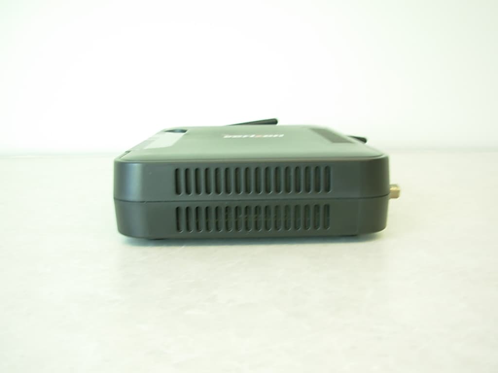
Authorized Agent: Radiometrics Midwest Corporation (815) 293-0772 – [email protected] External EUT Photographs Figure 1. Top of EUT Figure 2. Rear of EUT Figure 3. Bottom of EUT Authorized Agent: Radiometrics Midwest Corporation (815) 293-0772 – [email protected] Figure 4. Photograph of Power Supply: Front Figure 5. Photograph of Power Supply: Side
ID Label/Location Info
Authorized Agent: Radiometrics Midwest Corporation (815) 293-0772 – [email protected] ID Label/Location FCC ID: CH87500XX-07 Photograph of label The Label measures 3” by 2” The Label is made of a poly material and uses a UL-approved permanent adhesive Photograph showing placement of Label on EUT
Internal Photos
Authorized Agent: Radiometrics Midwest Corporation (815) 293-0772 – [email protected] Internal EUT Photographs The Antennas are the two long blue items on the edge of the PCB. Authorized Agent: Radiometrics Midwest Corporation (815) 293-0772 – [email protected] Figure 1. Photograph of Power Supply Board: Component Side Figure 2. Photograph of Power Supply Board: Foil Side
RF Exposure Info
Authorized Agent: Radiometrics Midwest Corporation (815) 293-0772 – [email protected] RF Exposure This calculation is based on the highest EIRP possible from the Remote or the Base considering maximum power and antenna gain. The following formulas were used: The highest PEAK output power of the EUT is 670 mW and the gain of the antenna is 2 dBi. This is not a hand held device. 1 MINIMUM SEPARATION DISTANCE PER OET 65 The following information provides the minimum separation distance for the EUT, as calculated from FCC OET 65 Appendix B, Table 1B “Guidelines for General Population/Uncontrolled Exposure” SMaximum AntennaMSD Freq.GP limitRF power GainEIRPEIRPd MHzmW/cm^2 dBmdBdBmwattsmeters 2437128.3230.31.0715 0.0923 GP is the limit for general Population/Uncontrolled Exposure MSD is the minimum Seperation Distance Notes on above table. (S) GP limit is from OET 65 table 1B EIRP = Power in dBm + Antenna Gain in dBi MSD (Minimum Separation Distance) = ((EIRP*30)/3770*S))^0.5 NOTE: For mobile or fixed location transmitters, minimum separation distance is 20 cm, even if calculations indicate MPE distance is less
Test Report
Radiometrics Midwest Corporation (815) 293-0772 – www.radiomet.com Page 1 of 29 Electromagnetic Compatibility Test Report Tests Performed on a Westell, Inc. Versalink Wifi Device, Model A90-750015-07 Radiometrics Document RP-6051 Product Detail: FCC ID: CH87500XX-07 Equipment type: Digital Transmission System Test Standards: US CFR Title 47, Chapter I, FCC Part 15 Subpart C FCC Part 15 CFR Title 47: 2006 Industry Canada RSS-210, Issue 7, June 2007 as required for Category I Equipment This report concerns: Original Grant for Certification FCC Part 15.247 Tests Performed For: Test Facility: Westell, Inc. 750 West Commons Dr. Aurora, IL 60504 Radiometrics Midwest Corporation 12 East Devonwood Romeoville, IL 60446 Test Date(s): (Month-Day-Year) May 4 thru 8, 2007 Document RP-6051 Revisions: Rev. Issue Date Affected Pages Revised By 0 December 06, 2007 RADIOMETRICS MIDWEST CORPORATION - EMC Test Report Testing of the Westell, Inc., Model A90-750015-07, Versalink RP-6051 Rev. 0 Page 2 of 29 Table of Contents 1 ADMINISTRATIVE DATA ................................................................................................................... 3 2 TEST SUMMARY AND RESULTS .....................................................................................................3 2.1 RF Exposure Compliance Requirements ..................................................................................... 3 3 EQUIPMENT UNDER TEST (EUT) DETAILS .................................................................................... 4 3.1 EUT Description ........................................................................................................................... 4 3.1.1 FCC Section 15.203 & RSS-GEN Antenna Requirements .................................................... 4 3.2 Related Submittals ....................................................................................................................... 4 4 TESTED SYSTEM DETAILS .....................................…
Text truncated - open the document above for the full version.
Contact Information
Applicant
Joseph Gage(Compliance Engineer)
Test Firm
Radiometrics Midwest Corp.Joseph Strzelecki
Technical Specifications
| # | Rule Parts | Frequency Range | Power Output |
|---|---|---|---|
| 1 | 15C | 2.41 GHz - 2.46 GHz | 670.00 mW |
Other Applications from Westell Inc
CH8MXX50
Jan 23, 2013Wireless Broadband Wi-Fi Router
Equipment Class
DTS - Digital Transmission System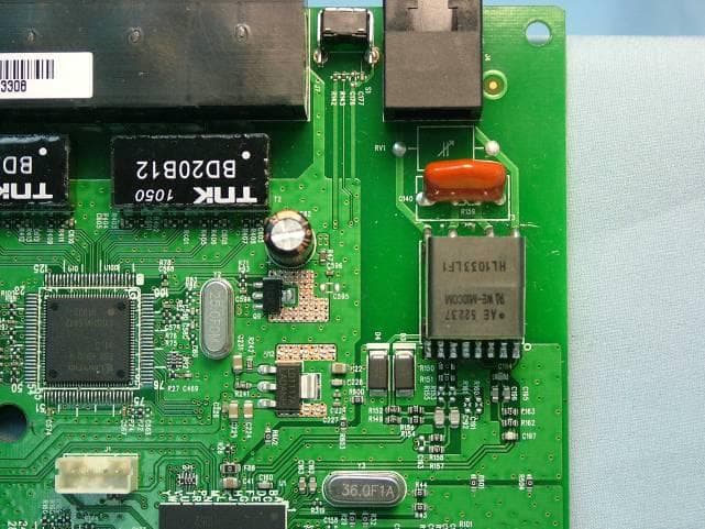
CH8B755
Mar 31, 2011VersaLink Wireless Gateway
Equipment Class
DTS - Digital Transmission System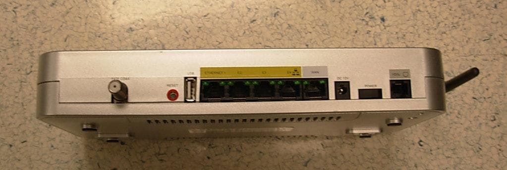
CH89100VMXX-10
Dec 08, 2007Wireless Broadband router with WiFi
Equipment Class
DTS - Digital Transmission System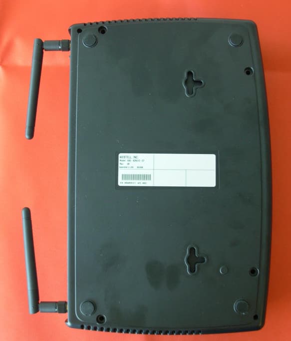
CH8A908260XX
Aug 29, 2006Wireless Gateway
Equipment Class
DTS - Digital Transmission System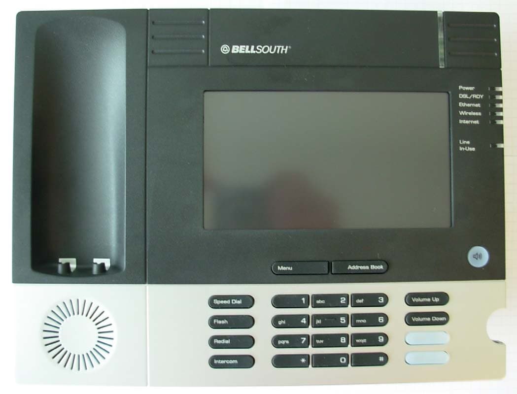
CH8A90WMT-00
Jul 10, 2006Media Terminal with Wireless LAN
Equipment Class
DTS - Digital Transmission System