CH8A90WMT-00Media Terminal with Wireless LAN
Westell Inc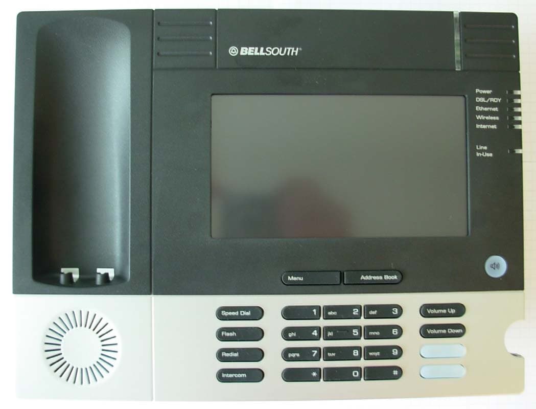
Click to zoom
Application Details
- Equipment Class
- DTS - Digital Transmission System
- Date of Grant
- Jul 10, 2006
- Application Purpose
- Original Equipment
- Date of Application
- Jul 10, 2006
- Equipment Note
- Media Terminal with Wireless LAN
- Frequency Range
- 2412.00000000 - 2462.00000000
- Company
- Westell Inc
- Country
- United States
Documents & Files
Document Text
Text extracted from the exhibit documents filed with the FCC. Open a document above to read the original.
Users Manual
Draft 1 – 07/11/06 Copyright © 2006 Westell, Inc.030-300417 Rev. A MEDIAGATEWAY™(MODELWMT) USERGUIDE Draft 1 - 07/11/06 030-300417 Rev. A 2 July 2006 Media Gateway (Model WMT) User Guide TABLE OF CONTENTS 1.PRODUCT DESCRIPTION ..................................................................................................................................4 2.SAFETY INSTRUCTIONS ...................................................................................................................................4 3.CARING FOR YOUR MEDIA GATEWAY.........................................................................................................4 4.REGULATORY INFORMATION ........................................................................................................................5 4.1FCC Compliance Note ...............................................................................................................................5 4.2Canada Certification Notice.....................................................................Error! Bookmark not defined. 5.NETWORKING REQUIREMENTS .....................................................................................................................7 6.HARDWARE FEATURES....................................................................................................................................8 6.1LED Indicators...........................................................................................................................................8 7.INSTALLING THE HARDWARE........................................................................................................................9 7.1Installation Requirements ..........................................................................................................................9 7.2Before you begin........................................................................................................................................9 7.3Hardware Installations .............................................................................................................................10 8.CONFIGURING MEDIA GATEWAY FOR INTERNET CONNECTION........................................................13 8.1Setting Up an Account Profile .................................................................................................................13 8.2Establishing a PPP Session ......................................................................................................................18 8.3Disconnecting a PPP Session ...................................................................................................................20 9.SETTING UP MACINTOSH OS X.....................................................................................................................22 10. SETTING UP ADVANCED CONFIGURATION ..............................................................................................26 11. HOME ..................................................................................................................................................................27 11.1Adding Account Profiles..........................................................................................................................28 11.2Editing Account Profiles ..........................................................................................................................29 12. STATUS...............................................................................................................................................................31 12.1Connection Summary...............................................................................................................................31 12.2About .......................................................................................................................................................32 13. CONFIGURATION .............................................................................................................................................33 13.1Single Static IP – Single IP Address PassThrough ..................................................................................33 13.2Service Configuration ..............................................................................................................................38 13.3Firewall Configuration.............................................................................................................................50 13.4Wireless Configuration ............................................................................................................................54 13.5Advanced LAN ........................................................................................................................................60 13.6Advanced WAN.......................................................................................................................................76 14. SETTING UP ADVANCED SERVICE CONFIGURATION.............................................................................90 14.1Port Forwarding Ranges of Ports .............................................................................................................91 Draft 1 - 07/11/06 030-300417 Rev. A 3 July 2006 Media Gateway (Model WMT) User Guide 14.2Adding Port Forwarding Ports .................................................................................................................91 14.3Port Forwarding Trigger Ports .................................................................................................................92 14.4Adding Local Trigger Ports .....................................................................................................................93 14.5Static NAT ...............................................................................................................................................94 14…
Text truncated - open the document above for the full version.
Users Manual
Draft 1 - 07/11/06 030-300417 Rev. A 61 July 2006 Media Gateway (Model WMT) User Guide require the name for identification purposes. new domain name and click Set. Static Host Assignment Host Name This field allows you to enter a HOST name for the Media Gateway. To add a new Host name, in the field under Static Host Assignment, type in the Host Name and the IP address and click Set. IP Address Displays the IP address that is assigned to the Host Name. Discover Local Devices This field displays a list of the computers on the LAN that were assigned a DHCP Address. The DNS name and IP address entry of each discovered device is displayed. (NOTE: The values in this field will be displayed barring any propagation delays. If ‘No Discovered Devices’ is displayed, manually refresh the screen.) If you want to add a new Host Name and IP address to your DNS server, enter the Gateway’s Host Name and IP Address in the fields provided in the Static Host Assignment section. Draft 1 - 07/11/06 030-300417 Rev. A 62 July 2006 Media Gateway (Model WMT) User Guide The following screen displays a Host Name and an IP Address in the fields. Now click on add. If you clicked on add, the following screen will be displayed. The Host Name and IP Address have been added to the Static Host Assignment. Draft 1 - 07/11/06 030-300417 Rev. A 63 July 2006 Media Gateway (Model WMT) User Guide 13.5.2 DHCP Configuration (Private LAN) The following settings will be displayed if you select DHCPfrom the Advanced LAN menu. DHCP Server This setting allows Media Gateway to automatically assign IP addresses to local devices connected on the LAN. Westell advises setting this to enabled for the private LAN. Off = DHCP Server is disabled Private LAN = DHCP addresses will be saved into the Private LAN configuration. Public LAN = DHCP addresses will be saved into the Public LAN configuration. This option is only available if the Public LAN DHCP server is enabled. NOTE: These addresses will be overwritten if your ISP supports dynamic setting of these values. DHCP Start Address Factory Default = 192.168.1.15 This field displays the first IP address that the DHCP server will provide. The DHCP Start Address must be within the IP address and lower than the DHCP End Address. You may use any number from 0 to 254 in this address. DHCP End Address Factory Default = 192.168.1.47 This field displays the last IP address that the DHCP server will provide. The DHCP End Address must be within the IP address and higher than the DHCP Start Address. You may use any number from 0 to 254 in this address. Draft 1 - 07/11/06 030-300417 Rev. A 64 July 2006 Media Gateway (Model WMT) User Guide DHCP Lease Time Factory Default = 01:00:00:00 Displays the amount of time the provided addresses will be valid, after which the DHCP client will usually re-submit a request. NOTE: DHCP Lease Time is displayed in the format (dd:hh:mm:ss)*. This value must be greater than 10 seconds. Seconds must be between 0 and 59, minutes must be between 0 and 59, and hours must be between 0 and 23. *(dd = days, hh = hours, mm = minutes, ss = seconds) 13.5.3 Disabling the DHCP Server If you click on the drop-down arrow at DHCP Server:, a list of options will be displayed. If you want to disable your DHCP server, select Offfrom the DHCP Server drop-down arrow. Click on save. Draft 1 - 07/11/06 030-300417 Rev. A 65 July 2006 Media Gateway (Model WMT) User Guide If you selected Off at DHCP Server:, the following screen will be displayed. Click on save to save the DHCP Server setting. If you clicked on save, in the preceding DHCP Configuration screen,the following pop-up screen will appear. Click on OK. STOP: After you disable the DHCP server, you must reboot your PC Draft 1 - 07/11/06 030-300417 Rev. A 66 July 2006 Media Gateway (Model WMT) User Guide 13.5.4 Enabling the DHCP Server If you want to enable your DHCP Server settings, select Private LAN at the DHCP Server drop-down arrow. If you have recently disabled the DHCP Server for Private LAN, select Private LAN while in the following screen. Draft 1 - 07/11/06 030-300417 Rev. A 67 July 2006 Media Gateway (Model WMT) User Guide If you selected Private LAN, the following screen will be displayed automatically. Click on save to save your DHCP Server setting. If you click on reset, your DHCP Server will be reset to factory default. (Private LAN is the factory default for the DHCP Server.) If you clicked on save, the following pop-up screen will appear. Click on OK. STOP: After you enable the DHCP server, you must reboot your PC Draft 1 - 07/11/06 030-300417 Rev. A 68 July 2006 Media Gateway (Model WMT) User Guide 13.5.5 Private LAN Configuration – Configuring NAT The following settings will be displayed if you select Private LAN from the Advanced LAN menu. (Private LAN is the default configuration for the Media Gateway.) NOTE: Private LAN allows you to set up a network behind the Media Gateway. If you change the settings in this screen, click on save. If you click on reset, the changes will not take effect. If you made changes and clicked on save, the following pop-up screen will be displayed. Click on OK. This will save your Private LAN Configuration settings. If you click Cancel, your new settings will not take effect. Private LAN DHCP Server Enable Default = CHECKED If this box is CHECKED, it enables DHCP addresses to be served from the Private LAN pool. Private LAN Enable Default = CHECKED Draft 1 - 07/11/06 030-300417 Rev. A 69 July 2006 Media Gateway (Model WMT) User Guide If this box is CHECKED, it enables the addresses from the Private LAN to use the NAT interface. Modem IP Address Displays the Media Gateway’s IP address Subnet Mask Displays the Subnet Mask, which determines what portion of an IP address is controlled by the network and which portion is controlled by the host. DHCP Start Address Displays the first IP address that the DHCP server will provide. DHCP End Address Displays the last IP address that the DHCP server will pr…
Text truncated - open the document above for the full version.
Cover Letter(s)
750 N. Commons Drive Aurora, Illinois 60504 (630) 898-2500 (800) 323-6883 (630) 375-4940 fax http://www.westell.com May 19, 2006 Federal Communications Commission Authorization and Evaluation Division 7435 Oakland Mills Rd. Columbia, MD 21046 Fax 301-344-2050 REFERENCE FCC ID: CH8A90WMT-00 Organization: Westell Inc. Request under 47 C.F.R. 0.459 that materials submitted to the commission be withheld from public inspection. Westell Inc. hereby requests that the materials attached here to be withheld from public inspection in accordance with 47 C.F.R. 0.459. Specifically, Westell Inc. requests that the following materials be withheld from public inspection under 47 C.F.R. 0.459 because the ADSL portion of the schematics are considered confidential trade secrets and technical data which customarily would be guarded from competitors: (1) Detailed Circuit Schematics of EUT are found in the FCC electronic attachments. (2) Block Diagrams found in the FCC electronic attachments. Therefore, in accordance with 47 C.F.R. 0.459, Westell Inc. requests that the above listed materials, copies of which are here to be withheld from public inspection. Authorized Signature: Date 5-19-2006 Albert L Engelkens Project Engineer Westell Inc.
External Photos
Authorized Agent: Radiometrics Midwest Corporation (815) 293-0772 – [email protected] FCC ID: CH8A90WMT-00 External EUT Photographs Front of EUT Authorized Agent: Radiometrics Midwest Corporation (815) 293-0772 – [email protected] Rear of EUT
ID Label/Location Info
750 NORTH COMMONS DRIVE AURORA, IL 60504 (630) 898-2500 (630) 323-6883 WWW.WESTELL.COM Sample Label and Location. Label The label is a polyester material with UL approved permanent adhesive. The label is located on the bottom center of the exterior of the product. The label measures approximately 2 inches wide by 1.25 inches high. The label is located on the bottom edge on the outside of the plastic enclosure. 750 NORTH COMMONS DRIVE AURORA, IL 60504 (630) 898-2500 (630) 323-6883 WWW.WESTELL.COM Label Location
Internal Photos
Authorized Agent: Radiometrics Midwest Corporation (815) 293-0772 – [email protected] FCC ID: CH8A90WMT-00 Internal EUT Photographs Photograph of RF PCB Board Top Authorized Agent: Radiometrics Midwest Corporation (815) 293-0772 – [email protected] Photograph of RF PCB Board Bottom Photographs of RF PCB and 2.4 GHz Antenna Authorized Agent: Radiometrics Midwest Corporation (815) 293-0772 – [email protected] Photograph showing Antenna inside EUT Photograph of Inside Front Cover Authorized Agent: Radiometrics Midwest Corporation (815) 293-0772 – [email protected] Photograph of Network Interface: Top Authorized Agent: Radiometrics Midwest Corporation (815) 293-0772 – [email protected] Photograph of Network Interface: Bottom Authorized Agent: Radiometrics Midwest Corporation (815) 293-0772 – [email protected] Photograph of Telephony LCD PC board: Bottom
Operational Description
Technical Description Model :WUBB-181G Wireless USB Network Adapter, Overview The Wireless LNA USB Network Adapter, model WUBB-181G is a USB Network Adapter, compliant with IEEE Std 802.11bg – 2002. This device operates in the 2.4GHz unlicensed Industrial, Scientific and Medical band and used Direct Sequence Spread Spectrum and OFDM communication techniques. WUBB- 181G is compatible with the USB 1.1 and USB 2.0 specification. To achieve maximum networking speeds (54Mbps), this device must be connection of this device to a USB 2.0 host port on a PC. Connection of this device to a USB 1.1 host port will yield a maximum of 11Mbps networking speed. Maximum power consumption is limited to less than 500mA (max).In some countries power and available bandwidth may be further reduced to meet regulatory requirements. The 2.4 GHz antenna is internal to the EUT and it is not readily available to be modified by the end user. Therefore it meets the 15.203 Requirement. The antenna is connected to the EUT with a unique adaptor not available to the general public. Functional Description The WUBB-181G is based on Broadcom’s two chip CMOS based 802.11b/g solution, namely the BCM4320 Baseband/MAC & System Interface and the BCM2050 Radio chipsets.. The BCM2050 zero IF Radio is an integrated transceiver device that has been optimized for use in 2.4-GHz wireless systems. It has been designed to provide low-power, low-cost, and robust communications for applications operating in the globally available 2.4-GHz unlicensed ISM band. It is fully compliant with the 802.11b and draft 802.11g specifications and meets or exceeds the requirements where appropriate to provide the highest communication link quality of service. The BCM2050 features a simple, innovative shared LO architecture that allows a high-performance radio implementation in a single CMOS chip. A proprietary PLL design generates quadrature LO signals in the 2.4-GHz band for both the transmitter and receiver. The PLL is locked to a 12-MHz free running crystal oscillator. A proprietary self-calibrating VCO is fully integrated frequency agile LO, ensures the lowest phase noise performance and covers the full 2.4-GHz ISM band. The receiver front end consists a low noise amplifier, a single side band mixer and on-chip low pass filter, which provide good performance without a costly external IF band pass filter. Because the entire receive channel is one chip, all sensitive components are eliminated from the board design and this leads to the most robust and noise-immune design, optimal for integration in laptop computers and embedded applications. The internal lowpass filter structure also features DC cancellation loop and self-calibration circuitry, which automatically adjusts circuit elements to compensate for any process variation. This eliminates tuning and ensures that the devices are uniform across process variation and temperature. An RSSI signal is also generated in these amplifiers for the system to determine signal strength. The output is a stable I/Q output for direct interface to the BCM43X X series of baseband/MAC components. The transmit signal is input through the I/Q input from the baseband. It is then filtered and upconverted to RF using the quadrature LO signals. The signal is then boosted to a minimum 1-mW output power level by an internal power amplifier. The output signal is optimized to enable easy integration with widely available power amplifiers and minimizes the linearity requirements for these devices. Output power control is digitally programmable from full power to low power in 4-dB steps. Technical Description Model :WUBB-181G Wireless USB Network Adapter, Page 2 of 2 The BCM2050 is controlled directly from the baseband and MAC through a fully digital control interface. This interface provides control for the various sections of the chip, defines data transfers and allows access to the various internal registers of the device. The BCM2050 is in a 64-pin LPCC package. The BCM4320 provides IEEE 802.11b/g MAC and baseband functions and interfaces to the BCM2050 to provide wireless LAN connectivity supporting data rates from 1 Mbps to 54Mbps. Broadcom’s direct conversion architecture virtually eliminates the additional external components typically required for 802.11b/g implementations, resulting in significant cost, power, and footprint savings. Additionally, industry-standardized WEP and WEP2 encryption coupled with IEEE 802.1x support is provided to ensure the security of transmitted data. Product Features • WHQL certifies drivers for Windows XP, Windows Millennium Edition, Windows 2000, and Windows 98SE. • Meets PCI power management interface v1.1 (ACPI) • IEEE 802.11b/g compliant MAC and baseband • WECA Wi-Fi November 2001 compliant • 24-bit IV and 40-bit key WEP encryption support • 24-bit IV and 104-bit key WEP encryption support • 128-bit IV and 128-bit key WEP2 encryption support • Software support for 128-bit OCB mode AES • IEEE 802.1x and LEAP support
RF Exposure Info
Authorized Agent: Radiometrics Midwest Corporation (815) 293-0772 – [email protected] RF exposure The 2.4 GHz transmitter Peak Power has a 23.3 dBm output with 2 dBi antenna gain The following information provides the minimum separation distance for the EUT, as calculated from FCC OET 65 Appendix B, Table 1B “Guidelines for General Population/Uncontrolled Exposure” This calculation is based on the highest EIRP possible from the EUT considering maximum power and antenna gain. The formulas were used: GP limit is = 1 mW/cm^2 above 1.5 GHz S= E^2/3770 mW/cm^2 E or V/m = (ERP*30)^0.5/d, (d in meters) d = ((ERP*30)/3770*S))^0.5 SPEAKAntennaMSD Freq.GP limitRF power GainERPEd MHzmW/cm^2 dBmdBiwattsV/mmeters 2462123.320.33961.40.052 GP is the limit for general Population/Uncontrolled Exposure MSD is the minimum Seperation Distance NOTE: For mobile or fixed location transmitters, minimum separation distance is 20 cm, even if calculations indicate MPE distance is less MPE for the transmitter is 20 cm.
Test Report
Radiometrics Midwest Corporation (815) 293-0772 – www.radiomet.com Page 1 of 32 Electromagnetic Compatibility Test Report Tests Performed on a Westell, Inc. Media Terminal, Model A90-WMT1030-00 Radiometrics Document RP-5833 Product Detail: FCC ID: CH8A90WMT-00 Equipment type: 2.4 GHz Digitally Modulated Transmitter Test Standards: US CFR Title 47, Chapter I, FCC Part 15 Subpart C FCC Part 15 CFR Title 47: 2006 This report concerns: Original Grant for Certification FCC Part 15.247 Tests Performed For: Test Facility: Westell, Inc. 750 N. Commons Dr. Aurora, IL 60504 Phone: 630-898-2500 Radiometrics Midwest Corporation 12 East Devonwood Romeoville, IL 60446 Phone: (815) 293-0772 e-mail: [email protected] Test Date(s): (Month-Day-Year) May 11 and 15, 2006 Document RP-5833 Revisions: Rev. Issue Date Affected Pages Revised By 0 June 23, 2006 RADIOMETRICS MIDWEST CORPORATION - EMC Test Report Testing of the Westell, Inc., Model A90-WMT1030-00, Media Terminal RP-5833 Rev. 0 Page 2 of 32 Table of Contents 1 ADMINISTRATIVE DATA ................................................................................................................... 3 2 TEST SUMMARY AND RESULTS .....................................................................................................3 3 EQUIPMENT UNDER TEST (EUT) DETAILS .................................................................................... 4 3.1 EUT Description ........................................................................................................................... 4 3.1.1 FCC Section 15.203 Antenna Requirements......................................................................... 4 3.2 Related Submittals ....................................................................................................................... 4 4 TESTED SYSTEM DETAILS .............................................................................................................. 4 4.1 Tested System Configuration ....................................................................................................... 4 4.2 Special Accessories ..................................................................................................................... 5 4.3 Equipment Modifications .............................................................................................................. 5 5 TEST SPECIFICATIONS AND RELATED DOCUMENTS.................................................................. 5 6 RADIOMETRICS’ TEST FACILITIES .................................................................................................5 7 DEVIATIONS AND EXCLUSIONS FROM THE TEST SPECIFICATIONS......................................... 6 8 CERTIFICATION ................................................................................................................................ 6 9 TEST EQUIPMENT TABLE ................................................................................................................ 6 10 TEST SECTIONS ............................................................................................................................. 7 10.1 AC Conducted Emissions; Section 15.207................................................................................. 7 Figure 1. Conducted Emissions Test Setup.................................................................................... 8 10.2 Occupied Bandwidth (6 dB)........................................................................................................ 9 10.3 Peak Output Power .................................................................................................................. 12 10.4 Power Spectral Density ............................................................................................................ 13 10.5 Band-edge Compliance of RF Conducted Emissions .............................................................. 13 10.6 Spurious RF Conducted Emissions.......................................................................................... 17 10.7 Spurious Radiated Emissions (Restricted Band) ..................................................................... 27 10.7.1 Radiated Emissions Field Strength Sample Calculation.................................................... 28 Figure 2. Drawing of Radiated Emissions Setup .......................................................................... 29 10.7.2 Spurious Radiated Emissions Test Results (Restricted Band) .......................................... 30 Notice: This report must not be reproduced (except in full) without the written approval of Radiometrics Midwest Corporation. RADIOMETRICS MIDWEST CORPORATION - EMC Test Report Testing of the Westell, Inc., Model A90-WMT1030-00, Media Terminal RP-5833 Rev. 0 Page 3 of 32 1 ADMINISTRATIVE DATA Equipment Under Test: A Westell, Inc., Media Terminal Model: A90-WMT1030-00 Serial Number: None This will be referred to as the EUT in this Report Date EUT Received at Radiometrics: (Month-Day-Year) Test Date(s): (Month-Day-Year) May 11, 2006 May 11 and 15, 2006 Test Report Written By: Test Witnessed By: Joseph Strzelecki Senior EMC Engineer Dan Wood Westell, Inc. Radiometrics’ Personnel Responsible for Test: Test Report Approved By Joseph Strzelecki Senior EMC Engineer NARTE EMC-000877-NE Chris W. Carlson Director of Engineering NARTE EMC-000921-NE 2 TEST SUMMARY AND RESULTS The EUT (Equipment Under Test) is a Media Terminal, Model A90-WMT1030-00, manufactured by Westell, Inc. The detailed test results are presented in a separate section. The following is a summary of the test results. This report pertains to the 802.11 section and the unintentional radiator section of the media terminal. Emissions Tests Results Environmental Phenomena Frequency Range Basic Standard Test Result RF Radiated Emissions 30 MHz to 25 GHz FCC Part 15 Pass Conducted Emissions, AC Mains 0.15 - 30 MHz FCC Part 15 Pass Spread Spectrum Transmitter Requirements Environm…
Text truncated - open the document above for the full version.
Test Setup Photos
Authorized Agent: Radiometrics Midwest Corporation (815) 293-0772 – [email protected] FCC ID: CH8A90WMT-00 Test Setup Photographs Photographs of Radiated Emissions Test Setup Note: The date on the photo is incorrect. The date was May 15 2006. Note: The date on the photo is incorrect. The date was May 11 2006. Authorized Agent: Radiometrics Midwest Corporation (815) 293-0772 – [email protected] Photograph of Conducted Emissions Test Setup Note: The date on the photo is incorrect. The date was May 15 2006. Photograph of Antenna Conducted Test Setup
Contact Information
Applicant
Joseph Gage(Compliance Engineer)
Test Firm
Radiometrics Midwest Corp.Joseph Strzelecki
Technical Specifications
| # | Rule Parts | Frequency Range | Power Output |
|---|---|---|---|
| 2 | 15C | 2.41 GHz - 2.46 GHz | 215.00 mW |
Other Applications from Westell Inc
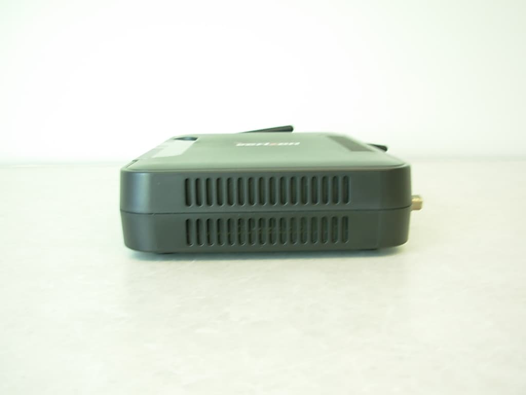
CH8MXX50
Jan 23, 2013Wireless Broadband Wi-Fi Router
Equipment Class
DTS - Digital Transmission System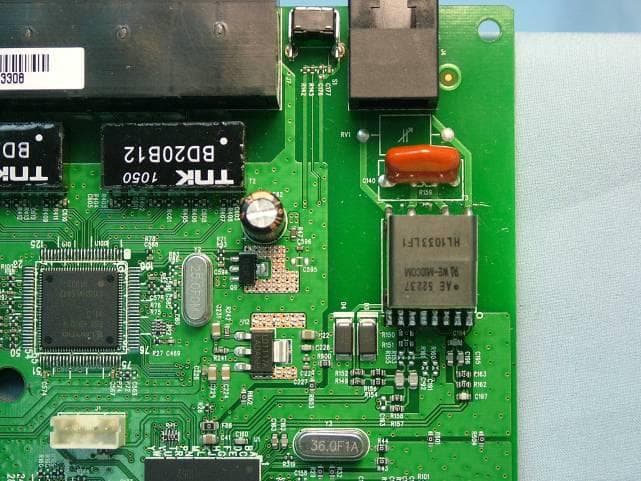
CH8B755
Mar 31, 2011VersaLink Wireless Gateway
Equipment Class
DTS - Digital Transmission System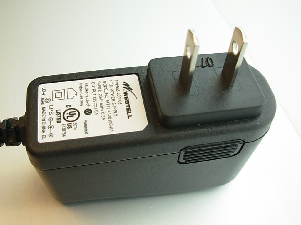
CH87500XX-07
Dec 20, 2007Versalink Wifi Device
Equipment Class
DTS - Digital Transmission System
CH89100VMXX-10
Dec 08, 2007Wireless Broadband router with WiFi
Equipment Class
DTS - Digital Transmission System
CH8A908260XX
Aug 29, 2006Wireless Gateway
Equipment Class
DTS - Digital Transmission System