CH8A90328XX-07Spread Spectrum Transmitter
Westell Inc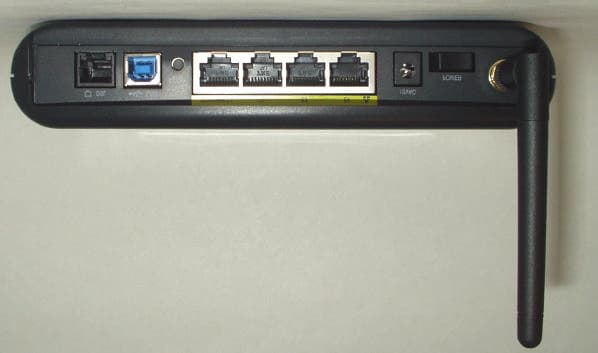
Click to zoom
Application Details
- Equipment Class
- DTS - Digital Transmission System
- Date of Grant
- Mar 30, 2005
- Application Purpose
- Original Equipment
- Date of Application
- Mar 30, 2005
- Equipment Note
- Spread Spectrum Transmitter
- Frequency Range
- 2402.00000000 - 2472.00000000
- Company
- Westell Inc
- Country
- United States
Documents & Files
Document Text
Text extracted from the exhibit documents filed with the FCC. Open a document above to read the original.
Users Manual
Copyright © 2004 Westell, Inc. 030-300432 Rev. A ULTRALINE (MODELS 7400/7401) V ERSALINK (MODELS 328W10/328W11) USER GUIDE 030-300432 Rev. A 2 December 2004 User Guide Westell Router (Models 7400, 7401, 328W10, 328W11) TABLE OF CONTENTS 1. PRODUCT DESCRIPTION ..................................................................................................................................4 2. SAFETY INSTRUCTIONS ...................................................................................................................................4 3. REGULATORY INFORMATION ........................................................................................................................5 3.1 FCC Compliance Note...............................................................................................................................5 3.2 Canada Certification Notice.......................................................................................................................6 4. NETWORKING REQUIREMENTS .....................................................................................................................8 5. HARDWARE FEATURES....................................................................................................................................9 5.1 LED Indicators...........................................................................................................................................9 5.2 Cable Connectors and Switch Locations .................................................................................................12 5.3 Connector Descriptions............................................................................................................................14 5.4 Pin-out Descriptions ................................................................................................................................16 6. INSTALLING THE HARDWARE......................................................................................................................17 6.1 Installation Requirements ........................................................................................................................17 6.2 Before you begin......................................................................................................................................17 6.3 Microfilters ..............................................................................................................................................17 6.4 Hardware Installations .............................................................................................................................18 7. INSTALLING THE USB DRIVERS (Models 7400, 328W10)...........................................................................23 7.1 CD-ROM Installation: .............................................................................................................................23 7.2 Installing the USB Drivers for Windows 98 SE ......................................................................................23 7.3 Installing the USB Drivers for Windows ME ..........................................................................................29 7.4 Installing the USB Driver for Windows 2000 .........................................................................................31 7.5 Installing the USB Driver for Windows XP ............................................................................................34 8. CONFIGURING THE ROUTER FOR INTERNET CONNECTION .................................................................36 8.1 Setting Up an Account Profile .................................................................................................................36 8.2 Confirming a DSL Sync ..........................................................................................................................41 8.3 Establishing a PPP Session ......................................................................................................................43 8.4 Disconnecting a PPP Session...................................................................................................................45 9. SETTING UP Macintosh OS X............................................................................................................................46 10. SETTING UP ADVANCED CONFIGURATION ..............................................................................................51 11. HOME ..................................................................................................................................................................52 11.1 Adding Account Profiles .........................................................................................................................53 11.2 Editing Account Profiles..........................................................................................................................54 12. STATUS...............................................................................................................................................................55 12.1 Connection Summary ..............................................................................................................................55 12.2 About .......................................................................................................................................................56 030-300432 Rev. A 3 December 2004 User Guide Westell Router (Models 7400, 7401, 328W10, 328W11) 13. CONFIGURATION .............................................................................................................................................57 13.1 Single Static IP – Single IP Address PassThrough ..................................................................................57 13.2 Service Configuration .........................................................................…
Text truncated - open the document above for the full version.
Users Manual
030-300432 Rev. A 61 December 2004 User Guide 13.1.2 Disabling Single Static IP – Single IP Address PassThrough To disable Single Static IP, select Single Static IP from the Configuration menu. Click on disable. If you clicked disable in the preceding screen, the following pop-up screen will be displayed. Click on OK. If you clicked OK in the Disable IP Passthrough? screen, the following pop-up screen will be displayed. This screen will allow the modem to be reset and the new configuration will take effect. Click on OK. 030-300432 Rev. A 62 December 2004 User Guide If you clicked OK in the preceding screen, the following screen will be displayed. The Router will be reset and the new configuration will take effect. After a brief delay, the home page will be displayed. Confirm that you have a DSL sync and that your PPP session displays UP. (Click on the connect button to establish a PPP session). Next, Select Single Static IP from the Configuration menu to confirm that Single Static IP is disabled, as shown in the following screen. STOP! After you disable Single Static IP, you must reboot your computer. 030-300432 Rev. A 63 December 2004 User Guide 13.2 Service Configuration The following settings will be displayed if you select Services from the Configuration menu. Westell has developed an extensive list of NAT services and you may select any service from this list. By selecting your specific NAT service and setting up a NAT profile, you will ensure that the appropriate ports on the Router are open and that the required application traffic can pass through your LAN. For a list of supported services, go to section 17 (NAT Services). NAT Profiles allow you to create specific service settings. The NAT profile may then be associated with a connection profile, allowing you to customize profiles for specific users. For example, if you want to attach specific NAT services to a profile, or if you want to set up a different connection setting for a profile, you can create new NAT profiles and customize them to your preference. NOTE: You may create up to four NAT profiles and attach an unlimited number of services to each profile. Current Profile Displays the NAT (Network Address Translation) services that you have selected. Service Name Drop down selection menu of NAT (Network Address Translation) service you can select to configure your Router. UPNP Enable Factory Default = Disable Enabling UPNP (Universal Plug and Play) allows automatic device discovery by your operating system. 030-300432 Rev. A 64 December 2004 User Guide 13.2.1 Configuring UPNP on your Router Note: To use the UPNP functionality in the Router, your Windows XP operating system must also support UPNP. Please contact your computer manufacturer to verify that UPNP is enabled in your Windows XP operating system. To enable UPNP on the Router perform the following steps: 1) Select Services from the Configuration menu. 2) Click the UPNP Enable box in the Service Configuration screen. A check mark will appear in the box. 3) Follow the instructions in the pop-up screens. 4) Click OK to reset the Router. NOTE: When you are ready to disable UPNP, uncheck the UPNP Enable box in the Service Configuration screen. If you click the UPNP Enable box in the Service Configuration screen, a check mark will appear in the box, as shown below. And the following pop-up screen will be displayed. Click on OK. 030-300432 Rev. A 65 December 2004 User Guide If you clicked OK in the preceding screen, the following screen will be displayed. Click on OK to reset the Router. If you clicked OK in the preceding screen, the following screen will be displayed. The Router will be reset automatically, and the new configuration will take effect. After a brief delay, the home page will be displayed. Confirm that you have a DSL sync and that your PPP session displays UP. (Click the connect button to establish a PPP session). 030-300432 Rev. A 66 December 2004 User Guide 13.2.2 Creating a New NAT Service Profile NAT Profiles allow you to create specific service settings. The NAT profile may then be associated with a connection profile, allowing you to customize profiles for specific users. For example, if you want to attach specific NAT services to a profile, or if you want to set up a different connection setting for a profile, you can create new NAT profiles and customize them to your preference. NOTE: You may create up to four NAT profiles and attach an unlimited number of services to each profile. To create a new NAT profile, click new in the Service Configuration screen. If you selected new from the preceding Service Configuration screen, the Create new Service Profile? pop-up screen will be displayed. Click on OK to begin creating your new NAT service profile. Click Cancel if you do not want to create a new NAT service profile. 030-300432 Rev. A 67 December 2004 User Guide If you clicked OK, the following screen will be displayed. Select “A New Service Profile #1” from the Current Profile drop-down arrow. If you selected “A New Service Profile #1” from the Current Profile drop-down arrow, the following screen will be displayed. This screen shows that you have chosen to create a new NAT service profile. You may create up to four NAT service profiles and attach an unlimited number of services to each profile. 030-300432 Rev. A 68 December 2004 User Guide 13.2.3 Editing a NAT Service Profile After you have created a NAT service profile, you may edit the profile’s name. If you select edit from the Service Configuration screen, the following screen will be displayed. By selecting the edit button, you can make changes to your profile name, and then add NAT services to or delete them from your profile. Type your new NAT service profile name in the field labeled Profile Name. The following screen shows that a new profile name called ‘My NAT Profile’ was entered into the Profile Name field. If you want save the new profile, click on save. If you do not want to save the new …
Text truncated - open the document above for the full version.
Users Manual
030-300432 Rev. A 111 December 2004 User Guide If you select ETHERNET PORT 1 from the WAN Port drop-down arrow, the following screen will be displayed. Click OK. If you click on OK in the preceding pop-up screen, the following screen will be displayed. Click on OK. If you click on Cancel, the change will not take effect. If you clicked on OK in the preceding pop-up screen, the following pop-up screen will appear. The Router must be reset to allow the new configuration to take effect. Click on OK. If you clicked on OK in the preceding screen, the following screen will be displayed. The Router will be reset and the new configuration will take effect. 030-300432 Rev. A 112 December 2004 User Guide After the Router has been reset, the DSL LED will be OFF. This is because the DSL transceiver has now been disabled. However, the Power, Ethernet, and Wireless LEDs will remain lit. 13.6.4 Editing the Router’s VC Configuration The following VC 1 Configuration screen will be displayed if you click on the edit button adjacent to any of the ‘Enabled’ protocols displayed in the WAN Configuration screen. (Note: The Protocol must be enabled before you can edit its VC configuration.) The VC 1 Configuration screen allows you to edit your virtual connection (VC). A virtual connection identifies a connection through the service provider’s ATM network to your ISP. Unlike physical hardware connections, virtual connections are defined by data. If you change any of the VC settings in the following screen, click the Set VC button to save the settings. NOTE: If you experience any problems, please reset the Router via the external hardware reset button or via the procedure defined under the Maintenance menu in section 15.1. The actual information displayed in this screen may vary, depending on network connection established. 030-300432 Rev. A 113 December 2004 User Guide VC 1 Configuration VPI This setting allows you to change your VPI (Virtual Path Indicator) value for a particular VC, which is defined by your Service Provider. VCI This setting allows you to change your VCI (Virtual Channel Indicator) value for a particular VC, which is defined by your Service Provider. PCR Factory Default = 100% Peak Cell Rate (PCR)-The maximum rate at which cells can be transmitted across a virtual circuit, specified in cells per second and defined by the interval between the transmission of the last bit of one cell and the first bit of the next. This value is a percentage of the current data rate. 100 allows this VC to use 100% of the available bandwidth. 80 allows this VC to use 80% of the available bandwidth. QoS Quality of Service, which is determined by your Service Provider. Possible Responses: CBR = Constant Bit Rate UBR = Unspecified Bit Rate VBR = Variable Bit Rate 030-300432 Rev. A 114 December 2004 User Guide Protocol The Protocol for each VC, which is specified by your Service Provider. Possible Responses: PPPoA = Point to Point Protocol over ATM (Asynchronous Transfer Mode) PPPoE = Point to Point Protocol over Ethernet Bridge = Bridge Protocol Classical IPoA = Internet Protocol over ATM (Asynchronous Transfer Mode). This is an ATM encapsulation of the IP protocol. Status The protocol status. VC x PPPoE Settings IP Address Displays the IP network address that your modem is on. Gateway Displays the Router’s IP address DNS Primary Provided by your Service Provider DNS Secondary Provided by your Service Provider MRU Negotiation Factory Default = DISABLED If ENABLED, the Maximum Received Unit (MRU) would enforce MRU negotiations. (NOTE: enable this option only at your Internet Service Provider’s request.) LCP Echo Disable Factory Default = Enable If checked, this option will disable the modem LCP Echo transmissions. LCP Echo Failures Indicates number of continuous LCP echo non-responses received before the PPP session is terminated. LCP Echo Retry Duration The interval between LCP Echo transmissions with responses. LCP Echo Retry Duration The interval between LCP. Echo after no response. Tunneling Factory Default = ENABLE If ENABLED, this option allows PPP traffic to be bridged to the WAN. This feature allows you to use a PPPoE shim on the host computer to connect to the Internet Service Provider, by bypassing the Router’s capability to do this. NOTE: Tunneling is available in PPPoE mode only. NOTE: The values for the IP Address, Gateway, DNS Primary, and DNS Secondary are all “Override of the value obtained from the PPP connection,” They default to “0.0.0.0,” in which case the override is ignored. Westell recommends that you do not change the values unless your Internet service provider instructs you to change them. 030-300432 Rev. A 115 December 2004 User Guide If you have made any changes to your VC settings, you need to save them. To save the new VC settings, click on OK when asked Set this PPPoE VC configuration? If you click on cancel, the new VC settings will not be saved. If you clicked on OK in the preceding pop-up screen, the following pop-up screen will appear. The Router must be reset to allow the new configuration to take effect. Click OK. If you clicked OK in the preceding screen, the following screen will be displayed. The Router will be reset and the new configuration will take effect. After a brief delay, the home page will be displayed. Confirm that you have a DSL sync and that your PPP session displays UP. (Click on the connect button to establish a PPP session). 030-300432 Rev. A 116 December 2004 User Guide 13.6.5 Configuring the Router’s Protocol Settings for PPPoE Mode If you are using Models 7400, 7401 select Advanced WAN > VC from the Configuration menu to configure the Router’s protocol settings for PPPoE mode. If you are using Models 328W10, 328W11, select Advanced WAN > WAN from the Configuration menu to configure the Router’s protocol settings for PPPoE mode. The VC Configuration screen will be displayed. Next, click on the edit button adjacent to any of the existing ‘Enabled’ VC (Virtual Co…
Text truncated - open the document above for the full version.
External Photos
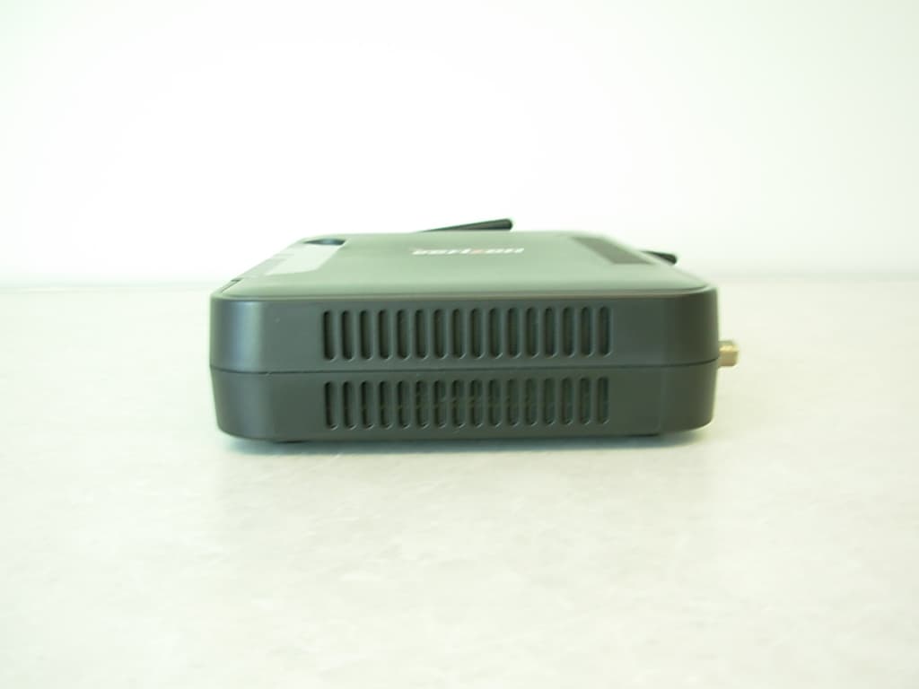
Authorized Agent: Radiometrics Midwest Corporation (815) 293-0772 – [email protected] External EUT Photographs FCC ID: CH8A90328XX-07 Front of EUT Rear of EUT Authorized Agent: Radiometrics Midwest Corporation (815) 293-0772 – [email protected] Front of Power Supply Side of Power Supply
ID Label/Location Info
Authorized Agent: Radiometrics Midwest Corporation (815) 293-0772 – [email protected] ID Label/Location FCC ID: CH8A90328XX-07 • Material to be mylar • Text to be Black with White letters • Permanent Adhesive • Size to be 33 x 53mm Drawing of label 53 by 33 mm The label will be on the bottom center of the unit. The label is compliant to UL 60950 Section 1.7.13 Durability of Markings. Radiometrics Midwest Corporation (815) 293-0772 – [email protected] Photograph of placement of label:
Internal Photos
Authorized Agent: Radiometrics Midwest Corporation (815) 293-0772 – [email protected] Internal EUT Photographs FCC ID: CH8A90328XX-07 Photo of Main PCB Authorized Agent: Radiometrics Midwest Corporation (815) 293-0772 – [email protected] Photo of Main PCB Authorized Agent: Radiometrics Midwest Corporation (815) 293-0772 – [email protected] Photos of RF PCB Authorized Agent: Radiometrics Midwest Corporation (815) 293-0772 – [email protected]
Operational Description
Radiometrics Midwest Corporation (815) 293-0772 – [email protected] Operational Description FCC ID: CH8A90328XX-07 VersaLink combines Westell's industry leading ADSL2+ modem technology with a high performance wireless and flexible router function. It provides wired networking using Ethernet and USB, and the convenience of 802.11g wireless. The optional uplink port (VersaPort™) transforms an Ethernet LAN port into an Ethernet WAN port for alternative access, including fiber, fixed wireless or connection to existing ADSL modems. For wireless gateway the radio used is an Abocom WMG2400V with FCC ID# of MQ4WMG2400. The 2.4 GHz antenna has a reverse polarity SMA connector on it. The antenna used is a 2 dBi monopole.
RF Exposure Info
RP-5394-RF Rev. 1 Page 1 of 1 RF exposure FCC ID: CH8 A90328XX-07 The 2.4 GHz transmitter Peak Power is 26.9 dBm output with 2 dBi antenna gain The following information provides the minimum separation distance for the EUT, as calculated from FCC OET 65 Appendix B, Table 1B “Guidelines for General Population/Uncontrolled Exposure” This calculation is based on the highest EIRP possible from the EUT considering maximum power and antenna gain. The formulas were used: GP limit is = 1 mW/cm^2 above 1.5 GHz S= E^2/3770 mW/cm^2 E or V/m = (ERP*30)^0.5/d, (d in meters) d = ((ERP*30)/3770*S))^0.5 SPEAKAntennaMSD Freq.GP limitRF powerGainERPEd MHzmW/cm^2dBmdBiwattsV/mmeters 2473126.920.77661.40.079 GP is the limit for general Population/Uncontrolled Exposure MSD is the minimum Seperation Distance NOTE: For mobile or fixed location transmitters, minimum separation distance is 20 cm, even if calculations indicate MPE distance is less MPE for the transmitter is 20 cm.
Test Report
Radiometrics Midwest Corporation (815) 293-0772 – www.radiomet.com Page 1 of 31 Electromagnetic Compatibility Test Report Tests Performed on a Westell, Inc. 4Port Wireless Gateway Router, Model Versalink Radiometrics Document RP-5422 Product Detail: FCC ID: CH8A90328XX-07 Equipment type: 2.4 GHz Digitally Modulated Transmitter. Test Standards: US CFR Title 47, Chapter I, FCC Part 15 Subpart C FCC Part 15 CFR Title 47: 2004 Industry Canada RSS-210, Issue 5 as required for Category I Equipment This report concerns: Original Grant for Certification FCC Part 15.247 Tests Performed For: Test Facility: Westell, Inc. 750 N. Commons Dr. Aurora, IL 60504 Radiometrics Midwest Corporation 12 East Devonwood Romeoville, IL 60446 Phone: (815) 293-0772 e-mail: [email protected] Test Date(s): (Month-Day-Year) January 25 to 28, 2005 Document RP-5422 Revisions: Rev. Issue Date Affected Pages Revised By Authorized Signature for Revision 0 March 24, 2005 RADIOMETRICS MIDWEST CORPORATION - EMC Test Report Testing of the Westell, Inc., Model Versalink, 4Port Wireless Gateway Router RP-5422 Rev. 0 Page 2 of 31 Table of Contents 1 ADMINISTRATIVE DATA........................................................................................................................3 2 TEST SUMMARY AND RESULTS.........................................................................................................3 3 EQUIPMENT UNDER TEST (EUT) DETAILS.......................................................................................4 3.1 EUT Description..............................................................................................................................4 3.1.1 FCC Section 15.203 & RSS-210 Section 5.5 Antenna Requirements....................................4 3.2 Related Submittals..........................................................................................................................4 4 TESTED SYSTEM DETAILS.................................................................................................................4 4.1 Tested System Configuration..........................................................................................................4 4.2 Special Accessories........................................................................................................................5 4.3 Equipment Modifications..................................................................................................................5 5 TEST SPECIFICATIONS AND RELATED DOCUMENTS....................................................................5 6 RADIOMETRICS’ TEST FACILITIES.....................................................................................................6 7 DEVIATIONS AND EXCLUSIONS FROM THE TEST SPECIFICATIONS............................................6 8 CERTIFICATION....................................................................................................................................6 9 TEST EQUIPMENT TABLE...................................................................................................................7 10 TEST SECTIONS................................................................................................................................7 10.1 AC Conducted Emissions; Section 15.207...................................................................................7 Figure 1. Conducted Emissions Test Setup...................................................................................10 10.2 Occupied Bandwidth (6 dB)........................................................................................................10 10.3 Peak Output Power.....................................................................................................................14 10.4 Power Spectral Density...............................................................................................................14 10.5 Band-edge Compliance of RF Conducted Emissions................................................................15 10.6 Spurious RF Conducted Emissions............................................................................................17 10.7 Spurious Radiated Emissions (Restricted Band).......................................................................27 10.7.1 Radiated Emissions Field Strength Sample Calculation......................................................27 Figure 2. Drawing of Radiated Emissions Setup............................................................................28 10.7.2 Spurious Radiated Emissions Test Results (Restricted Band)......................................28-31 Notice: This report must not be reproduced (except in full) without the written approval of Radiometrics Midwest Corporation. RADIOMETRICS MIDWEST CORPORATION - EMC Test Report Testing of the Westell, Inc., Model Versalink, 4Port Wireless Gateway Router RP-5422 Rev. 0 Page 3 of 31 1 ADMINISTRATIVE DATA Equipment Under Test: A Westell, Inc., 4Port Wireless Gateway Router Model: versalink Serial Number: none This will be referred to as the EUT in this Report Date EUT Received at Radiometrics: (Month-Day-Year) Test Date(s): (Month-Day-Year) November 11, 2004 January 25 to 28, 2005 Test Report Written By: Test Witnessed By: Joseph Strzelecki Senior EMC Engineer Dan Wood Westell, Inc. Radiometrics’ Personnel Responsible for Test: Test Report Approved By Joseph Strzelecki Senior EMC Engineer NARTE EMC-000877-NE Chris W. Carlson Director of Engineering NARTE EMC-000921-NE 2 TEST SUMMARY AND RESULTS The EUT (Equipment Under Test) is a 4Port Wireless Gateway Router, Model Versalink, manufactured by Westell, Inc.. The detailed test results are presented in a separate section. The following is a summary of the test results. Emissions Tests Results Environmental Phenomena Frequency Range Basic Standard Test Result RF Radiated Emissions 30 MHz to 25 GHz RSS-210 & FCC Part 15 Pass Conducted Emissions, AC Mains 0.15 - 30 MHz RS…
Text truncated - open the document above for the full version.
Test Setup Photos
Authorized Agent: Radiometrics Midwest Corporation (815) 293-0772 – [email protected] Test Setup Photographs FCC ID: CH8A90328XX-07 Photographs of Radiated Emissions Test Setup Authorized Agent: Radiometrics Midwest Corporation (815) 293-0772 – [email protected] Authorized Agent: Radiometrics Midwest Corporation (815) 293-0772 – [email protected] Photograph of Conducted Emissions Test Setup Authorized Agent: Radiometrics Midwest Corporation (815) 293-0772 – [email protected] Photograph of Antenna Conducted Emissions
Contact Information
Applicant
Joseph Gage(Compliance Engineer)
Test Firm
Bay Area Compliance LaboratoryJohn Chan
Technical Specifications
| # | Rule Parts | Frequency Range | Power Output |
|---|---|---|---|
| 1 | 15C | 2.40 GHz - 2.47 GHz | 500.00 mW |
Other Applications from Westell Inc
CH8MXX50
Jan 23, 2013Wireless Broadband Wi-Fi Router
Equipment Class
DTS - Digital Transmission System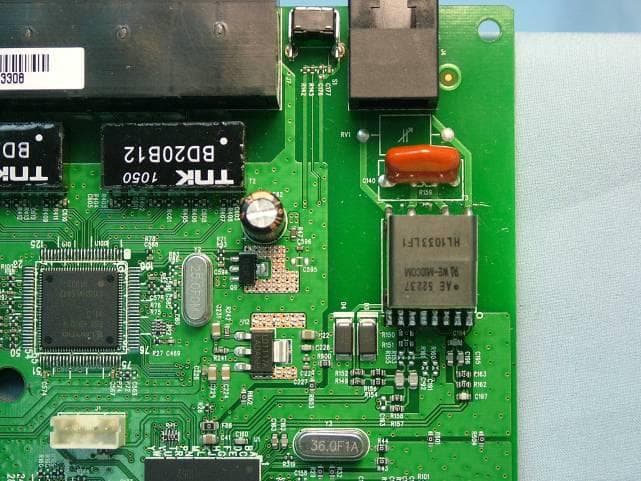
CH8B755
Mar 31, 2011VersaLink Wireless Gateway
Equipment Class
DTS - Digital Transmission System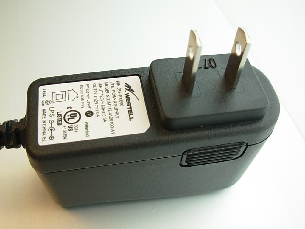
CH87500XX-07
Dec 20, 2007Versalink Wifi Device
Equipment Class
DTS - Digital Transmission System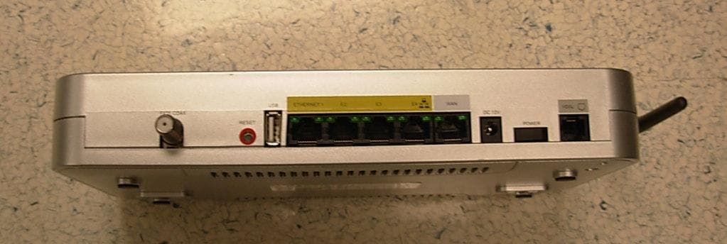
CH89100VMXX-10
Dec 08, 2007Wireless Broadband router with WiFi
Equipment Class
DTS - Digital Transmission System
CH8A908260XX
Aug 29, 2006Wireless Gateway
Equipment Class
DTS - Digital Transmission System