CH8A90VZ10XX06Spread Spectrum Transmitter
Westell Inc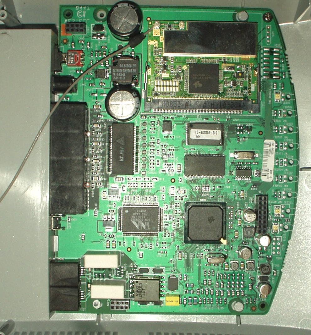
Click to zoom
Application Details
- Equipment Class
- DSS - Part 15 Spread Spectrum Transmitter
- Date of Grant
- Apr 07, 2005
- Application Purpose
- Original Equipment
- Date of Application
- Apr 07, 2005
- Equipment Note
- Spread Spectrum Transmitter
- Frequency Range
- 5728.50900000 - 5848.88900000
- Company
- Westell Inc
- Country
- United States
Documents & Files
Document Text
Text extracted from the exhibit documents filed with the FCC. Open a document above to read the original.
Users Manual
030-300419 Rev. A Draft 8 – 11/30/04 © Copyright 2004 Westell, Inc. 030-300419 Rev. A Draft 7 Changed power to AC 12V Draft 8 Updates section 3.1 Telephone Safety Instructions per Joe Gage VERIZON ONE TELEPHONE SUBSYSTEM 5.8 G HZ DIGITAL CORDLESS SPEAKERPHONE USER GUIDE 030-300419 Rev. A Draft 8– 11/30/04 030-300419 Rev. A 2 November 2004 User Guide Verizon One Telephone Subsystem TABLE OF CONTENTS 1. PRODUCT DESCRIPTION.................................................................................................................................4 2. CONVENTIONS USED IN THIS DOCUMENT ................................................................................................4 3. SAFETY INSTRUCTIONS .................................................................................................................................5 3.1 Telephone Safety Instructions ....................................................................................................................5 3.2 Battery Safety Instructions .........................................................................................................................5 4. REGULATORY INFORMATION ......................................................................................................................6 FCC Compliance Note ...........................................................................................................................................6 5. GETTING TO KNOW YOUR VERIZON ONE SYSTEM.................................................................................7 5.1 Caring for Your Verizon One .....................................................................................................................7 5.2 Base Unit Telephone Features ....................................................................................................................7 5.3 Cordless Handset Telephone Features........................................................................................................8 6. TELEPHONE SUBSYSTEM QUICK STARTUP...............................................................................................9 7. INSTALLING THE VERIZON ONE BASE UNIT...........................................................................................10 7.1 Choosing a Location to Install Verizon One ............................................................................................10 7.2 Installing the Base Unit on a Desktop or Flat Surface..............................................................................10 7.3 Wall Mounting on a Hollow Drywall Surface (Optional) ........................................................................10 8. INSTALLING THE VERIZON ONE HANDSET.............................................................................................12 8.1 Installing the Handset Battery ..................................................................................................................12 8.2 Charging the Handset (Battery) ................................................................................................................13 8.3 Battery Charge Indication.........................................................................................................................14 8.4 Turning On the Handset ...........................................................................................................................15 8.5 Parking the Handset on the Base ..............................................................................................................16 8.6 Using the Handset Belt Clip .....................................................................................................................16 9. REGISTERING THE HANDSET TO THE Verizon One BASE ......................................................................17 10. VERIZON ONE HANDSET CONTROLS ........................................................................................................18 10.1 Handset Control Buttons ..........................................................................................................................18 10.2 Handset Activity LED ..............................................................................................................................19 10.3 Backlighting .............................................................................................................................................19 11. Verizon One HANDSET SCREENS..................................................................................................................20 11.1 Standby .....................................................................................................................................................20 11.2 No New Calls ...........................................................................................................................................20 11.3 Twelve New Calls ....................................................................................................................................21 11.4 Ringer Off.................................................................................................................................................21 11.5 Fifteen New Calls, No Messages Waiting, Line In use ............................................................................21 11.6 Fifteen New Calls, Messages Waiting, Line In use ..................................................................................21 12. USING THE Verizon One MAIN MENU..........................................................................................................22 12.1 Accessing Handset Main Menu ................................................................................................................22 12.2 Registration Menu ....................................................................................................................................…
Text truncated - open the document above for the full version.
Users Manual
030-300419 Rev. A Draft 8– 11/30/04 030-300419 Rev. A 31 November 2004 User Guide Verizon One Telephone Subsystem 12.6.1.2 Phonebook is Full - No Entries Accepted from the Incoming Calls Log If you select [Save] in the “Save/Erase/Erase All” screen and phonebook detects that it is full, the following “Phonebook Full” screen will be displayed for 2 seconds. When the Phonebook is full, you must delete existing entries from the phonebook prior to saving new entries to the phonebook. 12.6.2 Erasing Calls from the Incoming Calls log To erase calls from the Incoming Calls log, first select [Incoming Calls] at the main menu screen. View the list of incoming calls and select the entry that you want to erase (delete). Next, select [Options] to display the following “Save/Erase/Erase All” screen. 030-300419 Rev. A Draft 8– 11/30/04 030-300419 Rev. A 32 November 2004 User Guide Verizon One Telephone Subsystem 12.6.2.1 Erasing Selected Entries Selecting [Erase] at the “Save/Erase/Erase All” screen enables you to delete specific Caller ID records from the Incoming Calls logs. To erase a selected entry, move the pointer to [Erase] and then select [Select]. The Handset LCD will display the following “Entry erased” screen, and after 2 seconds, the LCD will return to the next Caller ID record. Note: If there is only one record, and you choose to erase this record, the LCD will return to the Standby screen. 12.6.2.2 Erasing All Entries Selecting [Erase All] at the “Save/Erase/Erase All” screen enables you to delete all Caller ID records from the Incoming Calls logs. To erase all entries from the Incoming Calls log, move the pointer to [Erase All] and then select [Select]. The LCD will display the following [Erase all?] screen. Select [OK] to erase all entries in the Caller ID log. NOTE: If you do not want to erase all entries in the log, select [Exit] to return to the last Caller ID message in the log. If you select [OK] in the “Erase all?” screen, the following “List erased” screen will be displayed. After 2 seconds, the LCD will return to the Standby screen. 030-300419 Rev. A Draft 8– 11/30/04 030-300419 Rev. A 33 November 2004 User Guide Verizon One Telephone Subsystem 13. USING THE PHONEBOOK MENU 13.1 Accessing the Phonebook To access the Handset’s phonebook, select [Phonebook] in from Standby menu, the following screen will be displayed, and the pointer will be positioned at “(Add New Name).” Please choose one of the following options and then select [Select]: • Select [Select] while the pointer is positioned at (Add New Name) and perform the steps explained in section 13.2). • Press the <Up/Down> button to scroll through the list of Phonebook entries, and then select [Select] to select an entry. • Press a number (1 – 50) to go to an entry number in the phonebook. Note: The second digit is ignored if the number entered is greater than the number of entries in the Phonebook. • After selecting a phone entry, press the <TALK> button to go off-hook and dial the selected phone number. If there is no entry in the Phonebook, the “Empty List” message will be displayed in the screen. 030-300419 Rev. A Draft 8– 11/30/04 030-300419 Rev. A 34 November 2004 User Guide Verizon One Telephone Subsystem 13.2 Adding a New Name To add a new name, select [Select] when pointer is at (Add New Name). The following Name screen will be displayed. This screen will prompt you for Name information. Select one of the following options: NOTE: If the phonebook is full, you will not be able to enter a new name until entries are deleted from the phonebook. • Enter a name at the blinking underscore using the keypad characters (0-9, *, #). Note: If user tries to input more than 11 characters, an error tone will be emitted and additional input will not be accepted. While in the Name screen, you can select the [Clear] key to delete (backspace) characters. • Press the <OFF> button to return to the Standby screen. If the <Up/Down> button is pressed while you are at the Name screen, the Number screen will be displayed. Select one of the following options: • Enter a number at the blinking underscore using the keypad characters (0-9, *, #). Note: While in the “Number” screen, you can select the [Clear] key to delete (backspace) numbers. NOTE: Press the # symbol once to enter #. Press the # symbol twice to insert “P,” which is a 3-second pause during dialing. If you try to input more than 24 digits, an error tone will emit and digit input is not accepted.) The phone number will be formatted according to the following rules: String of digits Screen Format 1 7 digit number ###-#### 2 8 digits, leading digit 1 1 ###-#### 3 10 digits (###)###-#### 4 11 digits, leading digit 1 1(###)###-#### 5 Other cases No formatting 030-300419 Rev. A Draft 8– 11/30/04 030-300419 Rev. A 35 November 2004 User Guide Verizon One Telephone Subsystem • Press the <OFF> button to return to the Standby screen. • Press the <Up/Down> button to go back to the “Name” input screen. After you have entered the name and number into the screens, select [Save] to store the entry to the Phonebook. The entry will be listed in alphabetical order, and the list will be renumbered. After you select [Save], the following “Name Saved” screen will be displayed for 2 seconds. If you selected [Save] but did not enter a name into the name field, the empty name record is treated as "space" and is sorted to the beginning of the list regardless the number field, using first found/first display. The screen then returns to the Phonebook List at the “Add New Name” item. If you selected [Save] but did not enter a phone number entered has been entered, a “No Number Entered” message will be displayed on the screen for 2 seconds, an error tone will be emitted, and then the screen will return to the “number edit” screen. If the Phonebook is full when you select (Add New Name), a “Phonebook Full” message will be displayed for 2 seconds. When the Phonebook is full, you can store new a Name entry only aft…
Text truncated - open the document above for the full version.
Block Diagram
Authorized Agent: Radiometrics Midwest Corporation (815) 293-0772 – [email protected] Block Diagram Base and Handset RJ11FAX Port RJ11DSL Port POTS Splitter DSL Hybrid Data Processor 35.328MHz XTAL 802.11b/g Radio SDRAM FLASH Memory 4-Port Ethernet Switch RJ45 4-Ports Ethernet Port Circular DIN Power Power Supply Application Processor SDRAM FLASH Memory 25.000MHz XTAL 12.000MHz XTAL 5.8GHz Cordless Phone Radio 13.824MHz XTAL Rocker Switch On/Off Toggle Switch Reset Internal Diversity Antenna Internal Antenna LCD Display Keypad Audio Speaker Audio Microphone 32.768KHz XTAL Handset Cradle 40.000MHz XTAL 120MHZ CLK 100MHZ CLK 133MHZ CLK
Cover Letter(s)
Authorized Agent: Radiometrics Midwest Corporation (815) 293-0772 – [email protected] Confidentiality Letter FCC ID: CH8A90-VZ10XX06
ID Label/Location Info
Authorized Agent: Radiometrics Midwest Corporation (815) 293-0772 – [email protected] ID Label/Location FCC ID CH8A90VZ10XX06 Drawing of label as placed on EUT (Base Unit) Radiometrics Midwest Corporation (815) 293-0772 – [email protected] Close-up of FCC label on Base
Internal Photos
Authorized Agent: Radiometrics Midwest Corporation (815) 293-0772 – [email protected] Internal EUT Photographs FCC ID: CH8A90VZ10XX06 802.11 PCB cover off 802.11 PCB Authorized Agent: Radiometrics Midwest Corporation (815) 293-0772 – [email protected] 802.11 PCB cover on 5.8 GHz PCB Authorized Agent: Radiometrics Midwest Corporation (815) 293-0772 – [email protected] 5.8 GHz PCB Authorized Agent: Radiometrics Midwest Corporation (815) 293-0772 – [email protected] 5.8 GHz PCB Authorized Agent: Radiometrics Midwest Corporation (815) 293-0772 – [email protected] Photograph of EUT - case opened Authorized Agent: Radiometrics Midwest Corporation (815) 293-0772 – [email protected] PC Board – Component Side Authorized Agent: Radiometrics Midwest Corporation (815) 293-0772 – [email protected] PC Board – Inverter Section Authorized Agent: Radiometrics Midwest Corporation (815) 293-0772 – [email protected] PC Board – Foil Side Authorized Agent: Radiometrics Midwest Corporation (815) 293-0772 – [email protected] Speaker Board – Component Side Authorized Agent: Radiometrics Midwest Corporation (815) 293-0772 – [email protected] Speaker Board – Foil Side Authorized Agent: Radiometrics Midwest Corporation (815) 293-0772 – [email protected] ADSL Interface Board
Operational Description
Radiometrics Midwest Corporation (815) 293-0772 – [email protected] Operational Description FCC ID: CH8A90VZ10XX06 Overall Description Verizon One is an interactive device utilizing the power of PSTN and Broadband to deliver a feature rich and customer friendly service. This device will have all the standard features of a regular phone (Cordless Handset operating in the 5.8 GHz range , CID display, speakerphone, mute button, etc.) as well as an LCD display, and an integrated DSL modem and 802.11 WIFI router (to support connectivity to WiFi enabled devices throughout the home). On top of the normal phone features, this device will deliver a suite of services via the LCD screen, including o Proactive communications to guide DSL installation o Access to online Address Book with ability to touch the screen and automatically dial a number o Access to an online Calendar o Email notification w/ header information o Online Directory Searches – yellow and white page searches o CallerID log and ability to incorporate this information into an online Address Book o Real time call management o Schedule and manage call forwarding events, o Visual voice mail log, including name, number and time of message, o Instant access to information services like weather, news, stock quotes, movie listings, etc. WMG2400 A2 CIRCUIT DESCRIPTION HOST MAC BASE BAND TNETW1130 RADIO ANTENNA RF SWITCH CONTROL MAC (Media Access Control) Unit with Baseband Process Unit (U1) The TNETW1130 MAC implements the IEEE Std 802.11 MAC sublayer using both dedicated hardware and embedded firmware. The MAC hardware implements real-time functions, including access protocol management, encryption, decryption, and direct memory access (DMA) transferring of data between the baseband processor and the host. The eCPU runs firmware that manages the flow of commands and data to/from the host, performs scan-and-join operations, and maintains TX and RX queues, as well as a WEP key table stored in internal RAM. The eCPU can override many of the MAC functions that are performed automatically by hardware during normal operation. The baseband processor includes two primary interfaces: radio and MAC. The radio interface provides analog differential signals for transmitting and receiving data by means of 2.4-GHz or 5-GHz radios. The radio interface also includes programmable RX AGC, TX power control, and antenna diversity. The MAC interface ensures that decoded and descrambled RX data is transferred to the MAC for further processing. The MAC interface also allows the MAC to transfer MAC protocol data units (MPDUs) to the baseband processor for encoding and transmission. The baseband processor provides a serial interface through which the MAC accesses registers within the baseband processor core. The baseband processor also provides CCA information to the MAC. RC2422B RF Transceiver Dual-Mode 802.11b/g IQ/IF Transceiver with Dual VCO Synthesizers(U8) The RC2422 is a fully integrated IQ transceiver specifically for use in 802.11 b/g applications. The RC2422 is designed to perform the IQ conversion at 374MHz IF as well as provide an RFLO and control logic to the RFFE (Radio Frequency Front End). The RC2422 also has an internal IQ DC offset calibration function for the receive IQ interface. Combined with the Radia integrated RFFE, the RC2422 completes the Radia WLAN two-chip radio. The RC2422 incorporates all of the system blocks from the modem to the RFFE except for the IF filtering and the reference crystal. The ASIC uniquely incorporates an internal PLL reference oscillator where only a crystal is needed, and also provides a clock output for base-band/MAC ASICs. RC2422 includes two synthesizers with VCOs, IQ modulator, IQ demodulator, anti aliasing filters, IF amplifiers, receive AGC circuit, transmit power control and serial interface. RC2326 Dual-Mode 802.11b/g RFFE ISM band(U2) The RC2321 is a fully integrated Dual Mode Radio Frequency Front End (RFFE) designed specifically for use in 802.11 b/g applications. The RC2321 is designed to perform RF up and down conversions in the unlicensed ISM band. Combined with the Radia RC2422 IF/IQ Tranceiver/Synthesizer, The RC2326 completes the Radia WLAN two-chip radio. The RC2321 incorporates all of the RF blocks for both the “b/g” band except for low cost ceramic filters. The ASIC includes the LNA, PA, mixer, bias circuitry, RX gain control, transmit coupler detector, and T/R switches. High integration and internal RF matching enhances performance and greatly reduce external part count. The only external needed for operation are RF filters and external low power DC switching FETs. Power Regulator(U5,U10,U15) D3.3V Mini PCI Connector D3.3V A3.3V A2.85V A1.5V D1.5V A1.8V LDO Regulator(U5) Filter Transistor Dropout LDO Regulator(U15) LDO Regulator(U10) Digital supply for the TNETW1130 I/O Analog supply for Radio components Analog supply for the TNETW1130 Analog supply for the TNETW1130 Analog supply for the TNETW1130 Digital supply for the TNETW1130 core 802.11 Subsystem Supplies
RF Exposure Info
RP-5394-RF Rev. 1 Page 1 of 1 RF exposure FCC ID: CH8A90VZ10XX06 The 5.8 GHz transmitter Peak Power is 15.2 dBm output with 3 dBi antenna gain The 2.4 GHz transmitter Peak Power is 26.6 dBm output with 2 dBi antenna gain The following information provides the minimum separation distance for the EUT, as calculated from FCC OET 65 Appendix B, Table 1B “Guidelines for General Population/Uncontrolled Exposure” This calculation is based on the highest EIRP possible from the EUT considering maximum power and antenna gain. The formulas were used: GP limit is = 1 mW/cm^2 above 1.5 GHz S= E^2/3770 mW/cm^2 E or V/m = (ERP*30)^0.5/d, (d in meters) d = ((ERP*30)/3770*S))^0.5 SPEAKAntennaMSD Freq.GP limitRF powerGainERPEd MHzmW/cm^2dBmdBiwattsV/mmeters 2473126.620.72461.40.076 5850115.230.06661.40.023 GP is the limit for general Population/Uncontrolled Exposure MSD is the minimum Seperation Distance NOTE: For mobile or fixed location transmitters, minimum separation distance is 20 cm, even if calculations indicate MPE distance is less MPE for both transmitters is 20 cm.
Test Report
Radiometrics Midwest Corporation (815) 293-0772 – www.radiomet.com Page 1 of 1 Electromagnetic Compatibility Test Report Tests Performed on a Westell, Inc. Wireless Gateway & Cordless Phone, Model VZ1 Radiometrics Document RP-5394 Product Detail: FCC ID: CH8A90VZ10XX06 Equipment type: 2.4 GHz Digitally Modulated Transmitter. Test Standards: US CFR Title 47, Chapter I, FCC Part 15 Subpart C FCC Part 15 CFR Title 47: 2004 Industry Canada RSS-210, Issue 5 as required for Category I Equipment This report concerns: Original Grant for Certification FCC Part 15.247 Tests Performed For: Test Facility: Westell, Inc. 750 N. Commons Dr. Aurora, IL 60504 Radiometrics Midwest Corporation 12 East Devonwood Romeoville, IL 60446 Phone: (815) 293-0772 e-mail: [email protected] Test Date(s): (Month-Day-Year) November 11 thru December 14, 2004 Document RP-5394 Revisions: Rev. Issue Date Affected Pages Revised By Authorized Signature for Revision 0 March 10, 2005 RADIOMETRICS MIDWEST CORPORATION - EMC Test Report Testing of the Westell, Inc., Model VZ1, Wireless Gateway & Cordless Phone RP-5394 Rev. 0 Page 2 of 2 Table of Contents 1 ADMINISTRATIVE DATA........................................................................................................................3 2 TEST SUMMARY AND RESULTS.........................................................................................................3 3 EQUIPMENT UNDER TEST (EUT) DETAILS.......................................................................................4 3.1 EUT Description..............................................................................................................................4 3.1.1 FCC Section 15.203 & RSS-210 Section 5.5 Antenna Requirements....................................4 3.2 Related Submittals..........................................................................................................................4 4 TESTED SYSTEM DETAILS.................................................................................................................4 4.1 Tested System Configuration..........................................................................................................4 4.2 Special Accessories........................................................................................................................5 4.3 Equipment Modifications..................................................................................................................5 5 TEST SPECIFICATIONS AND RELATED DOCUMENTS....................................................................5 6 RADIOMETRICS’ TEST FACILITIES.....................................................................................................6 7 DEVIATIONS AND EXCLUSIONS FROM THE TEST SPECIFICATIONS............................................6 8 CERTIFICATION....................................................................................................................................6 9 TEST EQUIPMENT TABLE...................................................................................................................7 10 TEST SECTIONS................................................................................................................................7 10.1 AC Conducted Emissions; Section 15.207...................................................................................7 Figure 1. Conducted Emissions Test Setup.....................................................................................9 10.2 Occupied Bandwidth (6 dB)..........................................................................................................9 10.3 Peak Output Power.....................................................................................................................13 10.4 Power Spectral Density...............................................................................................................13 10.5 Band-edge Compliance of RF Conducted Emissions................................................................14 10.6 Spurious RF Conducted Emissions............................................................................................16 10.7 Spurious Radiated Emissions (Restricted Band).......................................................................26 10.7.1 Radiated Emissions Field Strength Sample Calculation......................................................26 Figure 2. Drawing of Radiated Emissions Setup............................................................................27 10.7.2 Spurious Radiated Emissions Test Results (Restricted Band)......................................27-31 Notice: This report must not be reproduced (except in full) without the written approval of Radiometrics Midwest Corporation. RADIOMETRICS MIDWEST CORPORATION - EMC Test Report Testing of the Westell, Inc., Model VZ1, Wireless Gateway & Cordless Phone RP-5394 Rev. 0 Page 3 of 3 1 ADMINISTRATIVE DATA Equipment Under Test: A Westell, Inc., Wireless Gateway & Cordless Phone Model: VZ1 Serial Number: none This will be referred to as the EUT in this Report Date EUT Received at Radiometrics: (Month-Day-Year) Test Date(s): (Month-Day-Year) November 11, 2004 November 11 thru December 14, 2004 Test Report Written By: Test Witnessed By: Joseph Strzelecki Senior EMC Engineer Dan Wood Westell, Inc. Radiometrics’ Personnel Responsible for Test: Test Report Approved By Joseph Strzelecki Senior EMC Engineer NARTE EMC-000877-NE Chris W. Carlson Director of Engineering NARTE EMC-000921-NE 2 TEST SUMMARY AND RESULTS The EUT (Equipment Under Test) is a Wireless Gateway & Cordless Phone, Model VZ1, manufactured by Westell, Inc.. The detailed test results are presented in a separate section. The following is a summary of the test results. This report pertains to the 802.11 section, and unintentional radiator section of the VZ1. Emissions Tests Results Environmental Phenomena Frequency Range Basic Standard Test Result RF Radia…
Text truncated - open the document above for the full version.
Test Report
Master: PT15C-FHT Date: February 7, 2002 Test Report: 4W36013, Issue 2 Applicant: Mitel Networks Corporation 350 Legget Drive Kanata Ontario Equipment Under Test: Verizon One Phone (EUT) FCC ID: In Accordance With: FCC Part 15.247, Subpart C FHSS System and Digitally Modulated Radiators 5725-5850MHz Tested By: Nemko Canada Inc. 303 River Road, R.R. 5 Ottawa, Ontario K1V 1H2 Authorized By: Sim Jagpal, General Manager Date: 17 January 2005 Total Number of Pages: 31 Nemko Canada Inc. FCC PART 15, SUBPART C FREQUENCY HOPPING TRANSMITTERS PROJECT NO.:4W36013 EQUIPMENT: Verizon One, Base Unit Page 2 of 31 Table of Contents Section 1. Summary of Test Results ...................................................................................3 Section 2. General Equipment Specification......................................................................5 Section 3. Powerline Conducted Emissions........................................................................6 Section 4. 20 dB Bandwidth...............................................................................................12 Section 5. Occupancy Time ...............................................................................................14 Section 6. Number of Hopping Channels .........................................................................16 Section 7. Minimum Channel Separation ........................................................................18 Section 8. Peak Output Power...........................................................................................20 Section 9. Spurious Emissions ...........................................................................................23 Section 10. Block Diagrams ..................................................................................................30 Section 11. Test Equipment List ..........................................................................................31 Nemko Canada Inc. FCC PART 15, SUBPART C FREQUENCY HOPPING TRANSMITTERS PROJECT NO.:4W36013 EQUIPMENT: Verizon One, Base Unit Page 3 of 31 Section 1. Summary of Test Results General All measurements are traceable to national standards. These tests were conducted on a sample of the equipment for the purpose of demonstrating compliance with Part 15, Subpart C. Radiated tests were conducted is accordance with ANSI C63.4-2001. Radiated emissions are made on an open area test site. A description of the test facility is on file with the FCC. THIS TEST REPORT RELATES ONLY TO THE ITEM(S) TESTED. THE FOLLOWING DEVIATIONS FROM, ADDITIONS TO, OR EXCLUSIONS FROM THE TEST SPECIFICATIONS HAVE BEEN MADE. See “ Summary of Test Data”. TESTED BY: _______________________________ DATE: 17 January 2005 Glen Westwell, Wireless Specialist Nemko Canada Inc. authorizes the above named company to reproduce this report provided it is reproduced in its entirety and for use by the company’s employees only. Any use which a third party makes of this report, or any reliance on or decisions to be made based on it, are the responsibility of such third parties. Nemko Canada Inc. accepts no responsibility for damages, if any, suffered by any third party as a result of decisions made or actions based on this report. This report applies only to the items tested. Nemko Canada Inc. FCC PART 15, SUBPART C FREQUENCY HOPPING TRANSMITTERS PROJECT NO.:4W36013 EQUIPMENT: Verizon One, Base Unit Page 4 of 31 Summary Of Test Data Name Of Test Para. No. Result Powerline Conducted Emissions 15.207(a) Complies 20 dB Bandwidth 15.247(a)(1)(ii) Comp…
Text truncated - open the document above for the full version.
Contact Information
Applicant
Joseph Gage(Compliance Engineer)
Test Firm
Nemko Canada Inc.Stuart Beck
Technical Specifications
| # | Rule Parts | Frequency Range | Power Output |
|---|---|---|---|
| 1 | 15C | 5.73 GHz - 5.85 GHz | 30.00 mW |
Other Applications from Westell Inc
CH8MXX50
Jan 23, 2013Wireless Broadband Wi-Fi Router
Equipment Class
DTS - Digital Transmission System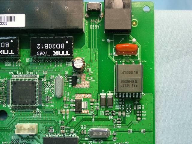
CH8B755
Mar 31, 2011VersaLink Wireless Gateway
Equipment Class
DTS - Digital Transmission System
CH87500XX-07
Dec 20, 2007Versalink Wifi Device
Equipment Class
DTS - Digital Transmission System
CH89100VMXX-10
Dec 08, 2007Wireless Broadband router with WiFi
Equipment Class
DTS - Digital Transmission System
CH8A908260XX
Aug 29, 2006Wireless Gateway
Equipment Class
DTS - Digital Transmission System