CH8D90327WXXX-064 Port Wireless Gateway Router
Westell Inc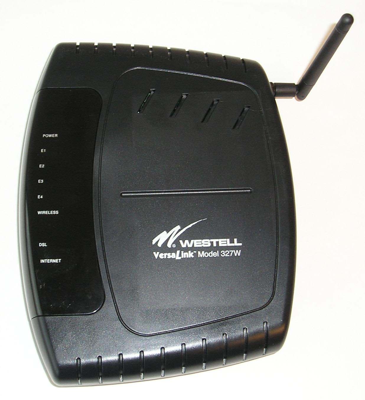
Click to zoom
Application Details
- Equipment Class
- DTS - Digital Transmission System
- Date of Grant
- Dec 07, 2005
- Application Purpose
- Original Equipment
- Date of Application
- Dec 07, 2005
- Equipment Note
- 4 Port Wireless Gateway Router
- Frequency Range
- 2412.00000000 - 2462.00000000
- Company
- Westell Inc
- Country
- United States
Documents & Files
Document Text
Text extracted from the exhibit documents filed with the FCC. Open a document above to read the original.
Users Manual
Copyright © 2005 Westell, Inc. 030-300469 Rev. A VERSALINK™ GATEWAY (MODEL 327W) USER GUIDE 7/29/03 DRAFT 2 (030-300361) 030-300469 Rev. A 2 September 2005 Westell (Model 6000, 6100, 6110) User Guide TABLE OF CONTENTS 1. PRODUCT DESCRIPTION ..................................................................................................................................3 2. SAFETY INSTRUCTIONS ...................................................................................................................................3 3. REGULATORY INFORMATION ........................................................................................................................4 3.1 FCC Compliance Note...............................................................................................................................4 3.2 Canada Certification Notice.......................................................................................................................5 7/29/03 DRAFT 2 (030-300361) 030-300469 Rev. A 3 September 2005 Westell (Model 6000, 6100, 6110) User Guide 1. PRODUCT DESCRIPTION The Westell® VersaLink™ Gateway provides reliable, high-speed, Internet access to your existing small office phone line. Your ADSL connection is “always-on” ending the hassles of dial-up modems and busy signals. Installation is easy ... no tools ... no headaches. Simply connect the hardware, apply power, and perform the simple software configuration for VersaLink and you are on the Internet. VersaLink™ is capable of data rates hundreds of times faster than a traditional analog modem. But unlike analog modems, VersaLink™ allows you to use the same phone line for simultaneous voice/fax communications and high- speed Internet access, eliminating the need for dedicated phone lines for voice and data needs. VersaLink™ supports a variety of networking interfaces such as wireless 802.11b/g/g+, ADSL, Ethernet and the following optional features: • VersaPort™: Alternate WAN uplink port • Layer w/2 QOS with VLAN tagging • HotSpot • Simultaneous public/private network support Hereafter, the Westell® VersaLink™ Gateway will be referred to as “VersaLink” or “Gateway.” There are two versions of the VersaLink: one with a USB port and one without a USB port. Features may vary depending on the model. Refer to section Error! Reference source not found. for model differences. 2. SAFETY INSTRUCTIONS • Never install any telephone wiring during a lightning storm. • Never install telephone jacks in wet locations unless the jack is specifically designed for wet locations. • Never touch non-insulated telephone wires or terminals unless the telephone line has been disconnected at the network interface. • Use caution when installing or modifying telephone lines. WARNING Risk of electric shock. Voltages up to 140 Vdc (with reference to ground) may be present on telecommunications circuits. 7/29/03 DRAFT 2 (030-300361) 030-300469 Rev. A 4 September 2005 Westell (Model 6000, 6100, 6110) User Guide 3. REGULATORY INFORMATION 3.1 FCC Compliance Note (FCC ID: CH8D90327WXX-06) This equipment has been tested and found to comply with the limits for a Class B digital device, pursuant to Part 15 of the Federal Communication Commission (FCC) Rules. These limits are designed to provide reasonable protection against harmful interference in a residential installation. This equipment generates, uses, and can radiate radio frequency energy, and if not installed and used in accordance with the instructions, may cause harmful interference to radio communications. However, there is no guarantee that interference will not occur in a particular installation. If this equipment does cause harmful interference to radio or television reception, which can be determined by turning the equipment OFF and ON, the user is encouraged to try to correct the interference by one or more of the following measures: • Reorient or relocate the receiving antenna. • Increase the separation between the equipment and the receiver. • Connect the equipment to a different circuit from that to which the receiver is connected. • Consult the dealer or an experienced radio/TV technician for help. This device complies with Part 15 of the FCC Rules. Operation is subject to the following two conditions: (1) This device may not cause harmful interference, and (2) this device must accept any interference received, including interference that may cause undesired operation. The antennas used for this transmitter must be installed to provide a separation distance of at least 20 cm from all persons and must not be co-located or operating in conjunction with any other antenna or transmitter. End users and installers must be provided with antenna installation instructions and transmitter operating conditions for satisfying RF exposure compliance. Modifications made to the product, unless expressly approved by Westell Inc., could void the users’ right to operate the equipment. PART 68 – COMPLIANCE REGISTRATION This equipment (Model 327W) complies with Part 68 of the FCC rules and the requirements adopted by the ACTA. A label on the bottom of this equipment contains, among other information, the Ringer Equivalence Number (REN) and the product identifier. For products approved after July 23, 2001 the product identifier is in the format US:AAAEQ##TXXXX. The digits represented by ## are the REN without a decimal point (e.g. 03 is a REN of 0.3). The REN is used to determine the number of devices that may be connected to a telephone line. For earlier products, the REN is separately shown on the label. If requested, this number must be provided to the telephone company. Excessive RENs on a telephone line may result in the devices not ringing in response to an incoming call. In most, but not all areas, the sum of RENs should not exceed five (5.0). To be certain of the number of devices that may be connected to a line, as determined by the total RENs, contact the local telephone company. This equ…
Text truncated - open the document above for the full version.
External Photos
Authorized Agent: Radiometrics Midwest Corporation (815) 293-0772 – [email protected] External EUT Photographs FCC ID: CH8D90327WXXX-06 Front of EUT Rear of EUT Authorized Agent: Radiometrics Midwest Corporation (815) 293-0772 – [email protected] Top of EUT Authorized Agent: Radiometrics Midwest Corporation (815) 293-0772 – [email protected] Bottom of EUT
ID Label/Location Info
FCC ID: CH8D90327XXX-06 D90-327W15-07 Sample Label The label is a polyester material with UL-approved permanent adhesive. The label is located on the bottom center of the exterior of the product. Label Location
Internal Photos
Authorized Agent: Radiometrics Midwest Corporation (815) 293-0772 – [email protected] Internal EUT Photographs FCC ID: CH8D90327WXXX-06 Photograph of RF PCB Component Side Authorized Agent: Radiometrics Midwest Corporation (815) 293-0772 – [email protected] Authorized Agent: Radiometrics Midwest Corporation (815) 293-0772 – [email protected] Photograph of RF PCB Foil Side Authorized Agent: Radiometrics Midwest Corporation (815) 293-0772 – [email protected] Photograph of EUT-Top Cover Removed; Shows component side of Main board Authorized Agent: Radiometrics Midwest Corporation (815) 293-0772 – [email protected] Photograph of Main board Foil Side
Operational Description
EUT Description Overview The RF section of the EUT is a digitally modulated Spread Spectrum transceiver for use as a wireless LAN. The EUT combines ADSL modem technology with a high performance wireless and flexible router function. It provides wired networking using Ethernet, and the convenience of 802.11b/g wireless. The optional uplink port transforms an Ethernet LAN port into an Ethernet WAN port for alternative access, including fiber, fixed wireless or connection to existing ADSL modems. The 2.4 GHz antenna has a reverse polarity SMA connector on it. The antenna used is a 2 dBi monopole. Detailed information The TNETW1350A chipset based 802.11 b/g wireless LAN card (The Card) is intended for the integration into communication or computing host systems such as a DSL router / modem. Mechanically, this card is built into the popular mini-PCI Type IIIB form factor so it can be easily inserted into a host system like a sub-system card. Electrically, however, this 802.11b/g card only has the Texas Instruments’ proprietary VLYNQ bus for the communication with host. The VLYNQ 2.6 is supported by 1350A. (two VLYNQ Interface at 1.8V or 3.3V(VLYNQ1, VLYNQ2)). And the card takes the 3.3V DC power from the host. The radio connections between the wireless LAN card and external antenna is through the coax cable.
RF Exposure Info
Authorized Agent: Radiometrics Midwest Corporation (815) 293-0772 – [email protected] RF exposure The output power of the EUT is 657 mW and the gain of the antenna is 2dBi The following information provides the minimum separation distance for the EUT, as calculated from FCC OET 65 Appendix B, Table 1B “Guidelines for General Population/Uncontrolled Exposure” This calculation is based on the highest EIRP possible from the EUT considering maximum power and antenna gain. The formulas were used: GP limit is = 1 mW/cm^2 for 2400 MHz Pwatts*Ggain or ERP = 10^(PdBm-30+GdBi)/10) = 1.047 Watts S= E^2/3770 mW/cm^2 E or V/m = (ERP*30)^0.5/d, (d in meters) d = ((ERP*30)/3770*S))^0.5 SMaximum AntennaMSD Freq.GP limitRF power GainERPEd MHzmW/cm^2 dBmdBiwattsV/mmeters 2240128.221.04761.40.091 GP is the limit for general Population/Uncontrolled Exposure MSD is the minimum Seperation Distance NOTE: For mobile or fixed location transmitters, minimum separation distance is 20 cm, even if calculations indicate MPE distance is less
Test Report
Radiometrics Midwest Corporation (815) 293-0772 – www.radiomet.com Page 1 of 34 Electromagnetic Compatibility Test Report Tests Performed on a Westell, Inc. VersaLink Wireless Gateway Router, Model D90327W15-06 Radiometrics Document RP-5671 Product Detail: FCC ID: CH8D90327WXXX-06 Equipment type: 2.4 GHz Digitally Modulated Transmitter. Test Standards: US CFR Title 47, Chapter I, FCC Part 15 Subpart C FCC Part 15 CFR Title 47: 2004 Industry Canada RSS-210, Issue 5 as required for Category I Equipment This report concerns: Original Grant for Certification FCC Part 15.247 Tests Performed For: Test Facility: Westell, Inc. 750 N. Commons Dr. Aurora, IL 60504 Radiometrics Midwest Corporation 12 East Devonwood Romeoville, IL 60446 Phone: (815) 293-0772 e-mail: [email protected] Test Date(s): (Month-Day-Year) September 21 to October 7, 2005 Document RP-5671 Revisions: Rev. Issue Date Affected Pages Revised By Authorized Signature for Revision 0 November 22, 2005 RADIOMETRICS MIDWEST CORPORATION - EMC Test Report Testing of the Westell, Inc., Model D90327W15-06, VersaLink Wireless Gateway Router RP-5671 Rev. 0 Page 2 of 34 Table of Contents 1 ADMINISTRATIVE DATA ................................................................................................................... 3 2 TEST SUMMARY AND RESULTS .....................................................................................................3 3 EQUIPMENT UNDER TEST (EUT) DETAILS .................................................................................... 4 3.1 EUT Description ........................................................................................................................... 4 3.1.1 FCC Section 15.203 & RSS-210 Section 5.5 Antenna Requirements ................................... 4 3.2 Related Submittals ....................................................................................................................... 4 4 TESTED SYSTEM DETAILS .............................................................................................................. 4 4.1 Tested System Configuration ....................................................................................................... 4 4.2 Special Accessories ..................................................................................................................... 5 4.3 Equipment Modifications .............................................................................................................. 5 5 TEST SPECIFICATIONS AND RELATED DOCUMENTS.................................................................. 5 6 RADIOMETRICS’ TEST FACILITIES .................................................................................................5 7 DEVIATIONS AND EXCLUSIONS FROM THE TEST SPECIFICATIONS......................................... 6 8 CERTIFICATION ................................................................................................................................ 6 9 TEST EQUIPMENT TABLE ................................................................................................................ 7 10 TEST SECTIONS ............................................................................................................................. 7 10.1 AC Conducted Emissions; Section 15.207................................................................................. 7 Figure 1. Conducted Emissions Test Setup.................................................................................... 9 10.2 Occupied Bandwidth .................................................................................................................. 9 10.3 Peak Output Power .................................................................................................................. 15 10.4 Power Spectral Density ............................................................................................................ 16 10.5 Band-edge Compliance of RF Conducted Emissions .............................................................. 16 10.6 Spurious RF Conducted Emissions.......................................................................................... 20 10.7 Spurious Radiated Emissions (Restricted Band) ..................................................................... 30 10.7.1 Radiated Emissions Field Strength Sample Calculation.................................................... 30 Figure 2. Drawing of Radiated Emissions Setup .......................................................................... 31 10.7.2 Spurious Radiated Emissions Test Results (Restricted Band) .......................................... 31 Notice: This report must not be reproduced (except in full) without the written approval of Radiometrics Midwest Corporation. RADIOMETRICS MIDWEST CORPORATION - EMC Test Report Testing of the Westell, Inc., Model D90327W15-06, VersaLink Wireless Gateway Router RP-5671 Rev. 0 Page 3 of 34 1 ADMINISTRATIVE DATA Equipment Under Test: A Westell, Inc., VersaLink Wireless Gateway Router Model: D90327W15-06 Serial Number: 6881 This will be referred to as the EUT in this Report Date EUT Received at Radiometrics: (Month-Day-Year) Test Date(s): (Month-Day-Year) September 21, 2005 September 21 thru October 7, 2005 Test Report Written By: Test Witnessed By: Joseph Strzelecki Senior EMC Engineer Timothy Lim Westell, Inc. Radiometrics’ Personnel Responsible for Test: Test Report Approved By Joseph Strzelecki Senior EMC Engineer NARTE EMC-000877-NE Chris W. Carlson Director of Engineering NARTE EMC-000921-NE 2 TEST SUMMARY AND RESULTS The EUT (Equipment Under Test) is a VersaLink Wireless Gateway Router, Model D90327W15-06, manufactured by Westell, Inc. The detailed test results are presented in a separate section. The following is a summary of the test results. Emissions Tests Results Environmental Phenomena Frequency Range Basic Standard Test Result RF Radiated Emissions 30 MHz to 25 GHz RSS-210 & FCC Part 15 Pass Con…
Text truncated - open the document above for the full version.
Test Setup Photos
Authorized Agent: Radiometrics Midwest Corporation (815) 293-0772 – [email protected] Test Setup Photographs FCC ID: CH8D90327WXX-06 Photographs of Radiated Emissions Test Setup Authorized Agent: Radiometrics Midwest Corporation (815) 293-0772 – [email protected] Photograph of Conducted Emissions Test Setup Antenna Conducted Emissions Authorized Agent: Radiometrics Midwest Corporation (815) 293-0772 – [email protected]
Contact Information
Applicant
Joseph Gage(Compliance Engineer)
Test Firm
Radiometrics Midwest Corp.Joseph Strzelecki
Technical Specifications
| # | Rule Parts | Frequency Range | Power Output |
|---|---|---|---|
| 1 | 15C | 2.41 GHz - 2.46 GHz | 657.00 mW |
Other Applications from Westell Inc
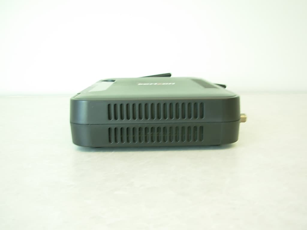
CH8MXX50
Jan 23, 2013Wireless Broadband Wi-Fi Router
Equipment Class
DTS - Digital Transmission System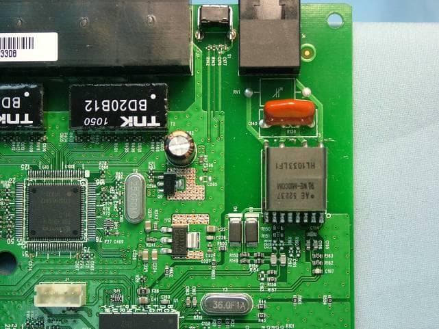
CH8B755
Mar 31, 2011VersaLink Wireless Gateway
Equipment Class
DTS - Digital Transmission System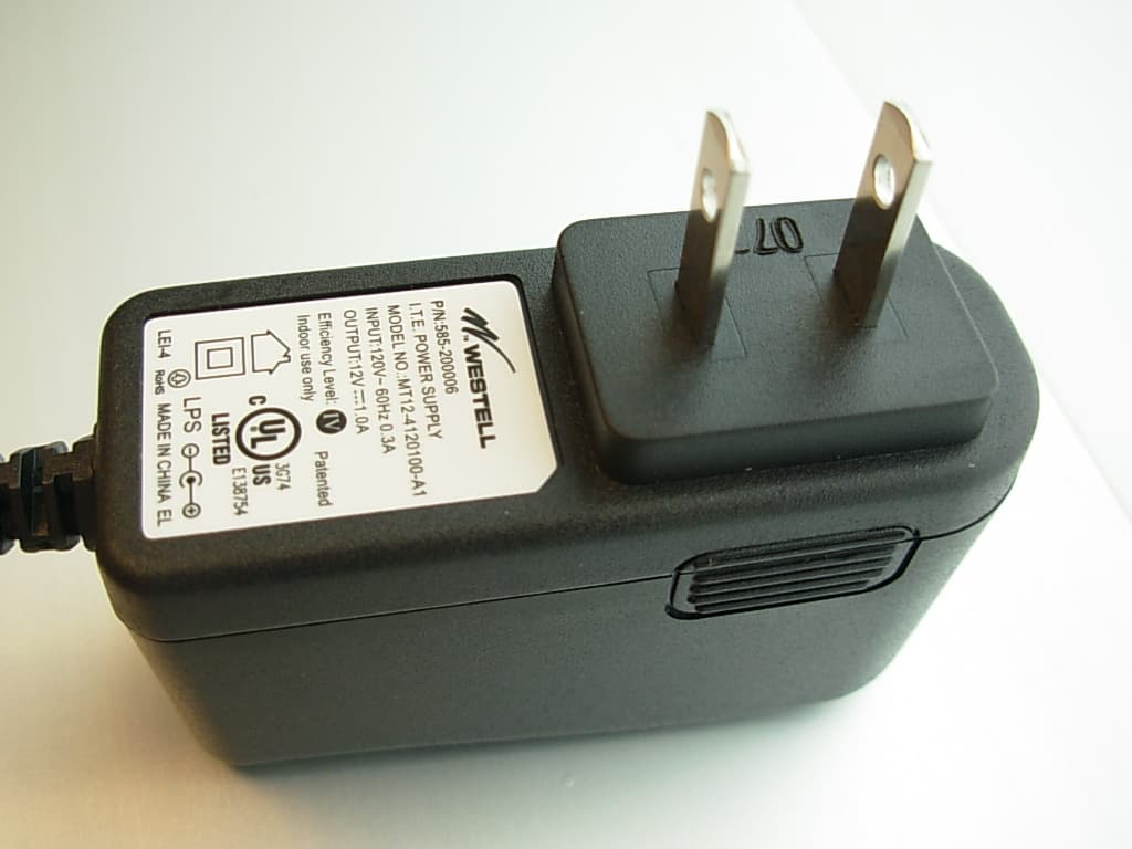
CH87500XX-07
Dec 20, 2007Versalink Wifi Device
Equipment Class
DTS - Digital Transmission System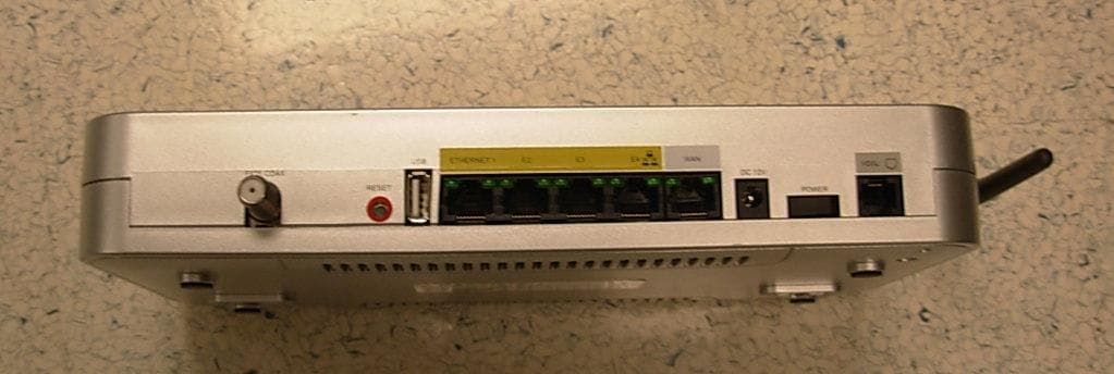
CH89100VMXX-10
Dec 08, 2007Wireless Broadband router with WiFi
Equipment Class
DTS - Digital Transmission System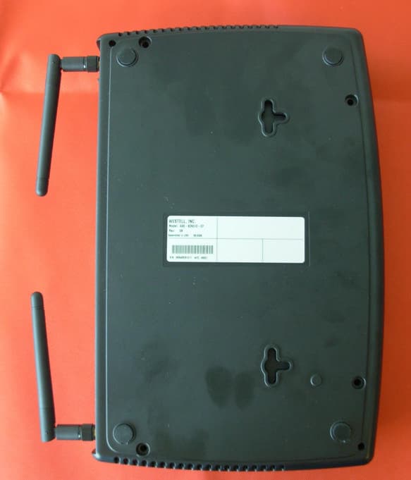
CH8A908260XX
Aug 29, 2006Wireless Gateway
Equipment Class
DTS - Digital Transmission System