CNVCCII-7-DCarry Coder II
Broadcast Microwave Services Inc
Click to zoom
Application Details
- Equipment Class
- TNB - Licensed Non-Broadcast Station Transmitter
- Date of Grant
- Jun 21, 2005
- Application Purpose
- Original Equipment
- Date of Application
- Jun 21, 2005
- Equipment Note
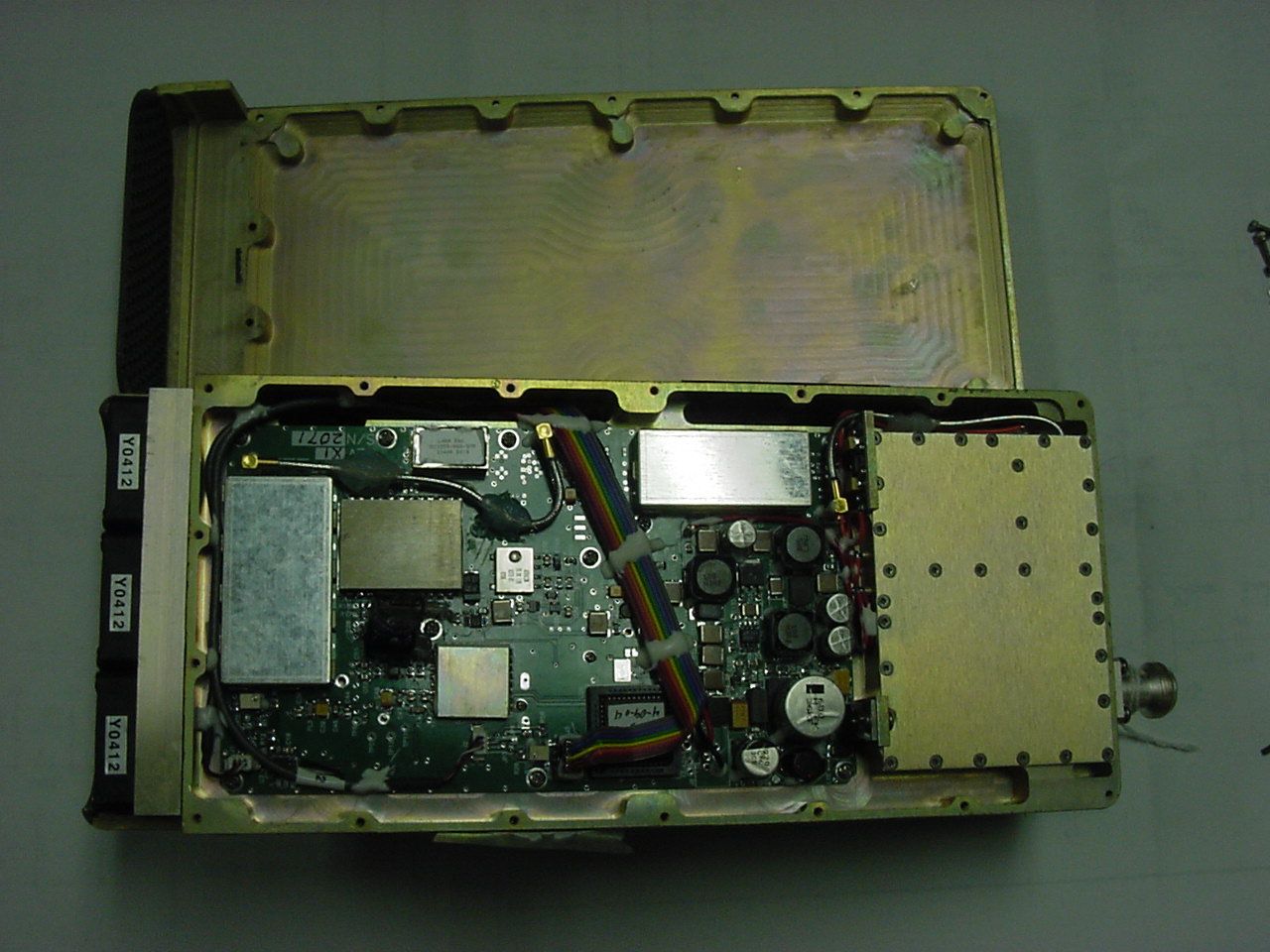
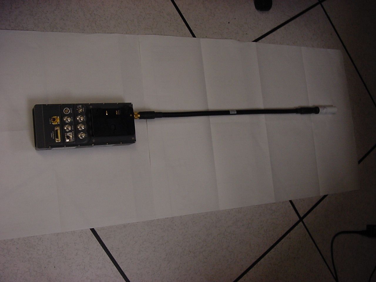
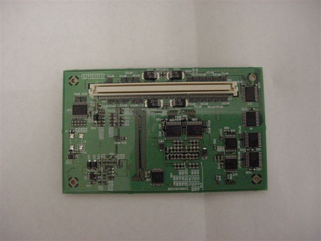
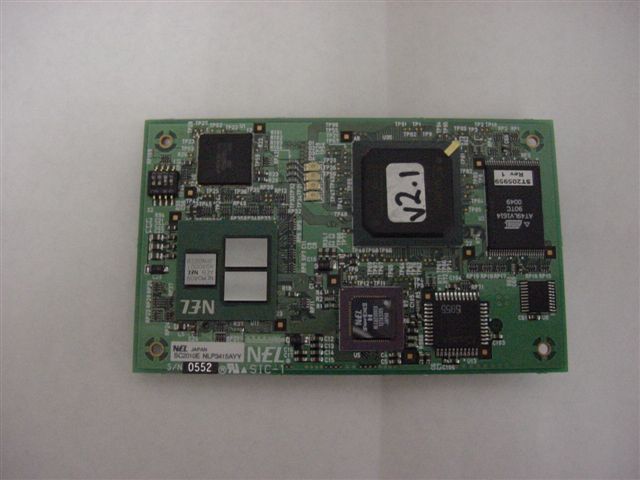
- Carry Coder II
- Frequency Range
- 1990.00000000 - 2500.00000000
- Country
- United States
Documents & Files
Document Text
Text extracted from the exhibit documents filed with the FCC. Open a document above to read the original.
ID Label/Location Info
LABEL REQUIREMENTS RF FCC Broadcast Microwave Services, Inc. Model No.: CCII-7 FCC ID: CNVCCII-7-D Made in USA Size is 1.5 inches Tall by 3 inches Wide MUST APPEAR ON THE OUTSIDE OF THE CERTIFIED UNIT. ALL INFORMATION MUST APPEAR ON THE LABEL.
Parts List/Tune Up Info
Upon turning the CCII-7 on, the unit requires no tuning. Brian Lucas Senior Design Engineer 12367 Crosthwaite Circle Poway , CA 92064 Phone: 858 391 3050 x134 EMAIL: [email protected]
RF Exposure Info
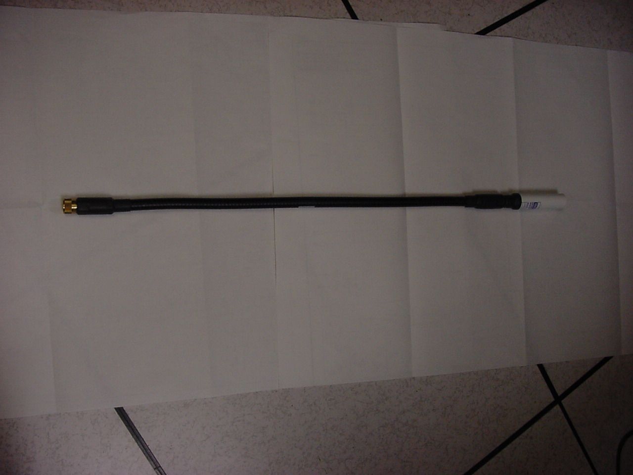
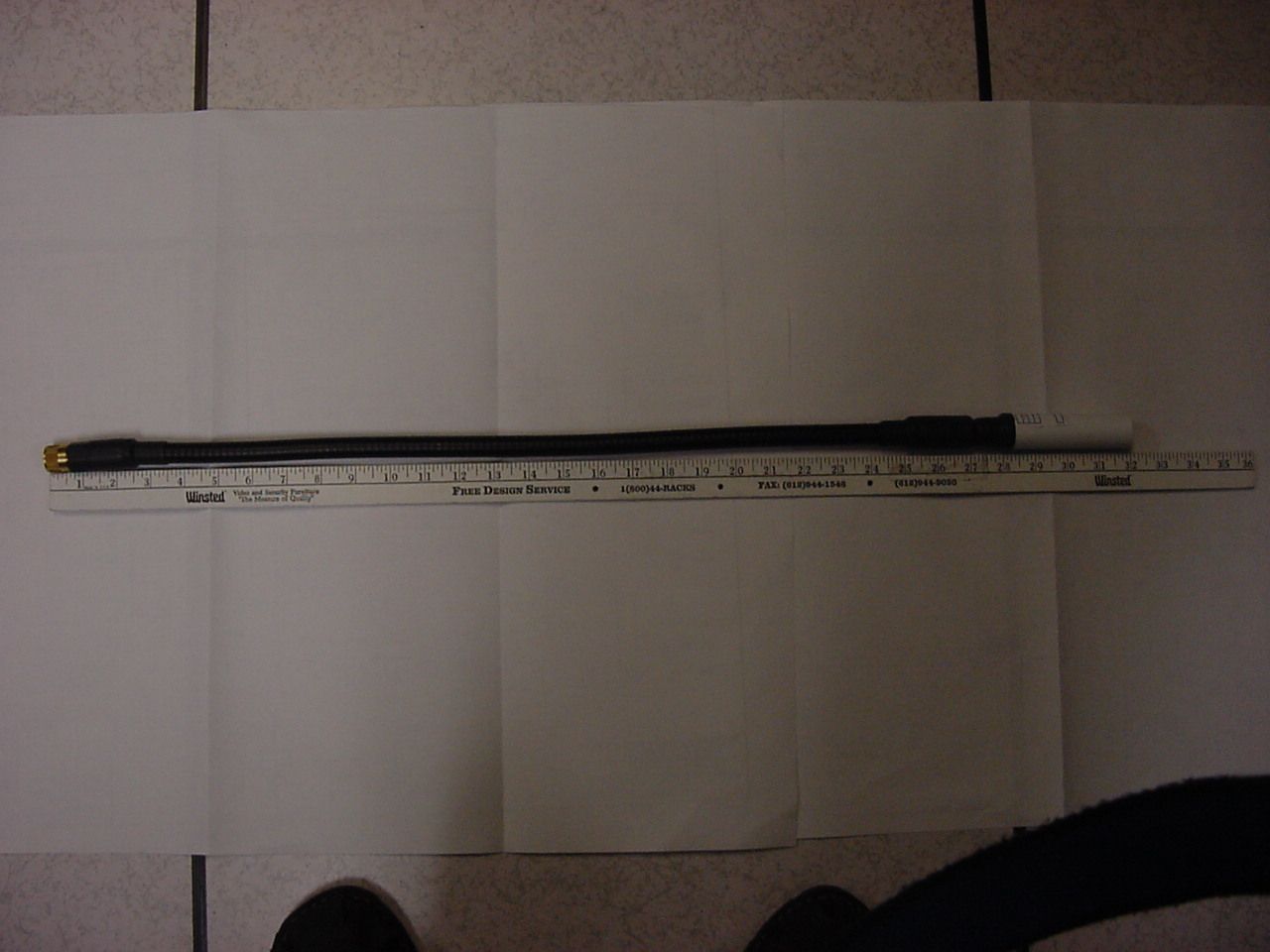
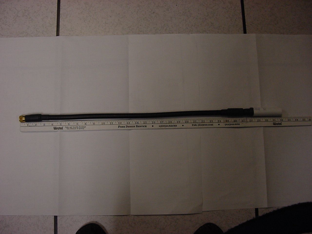
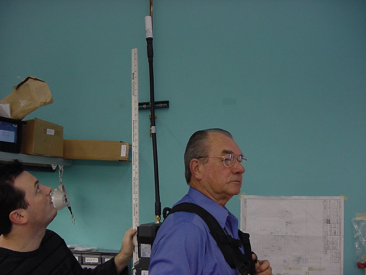
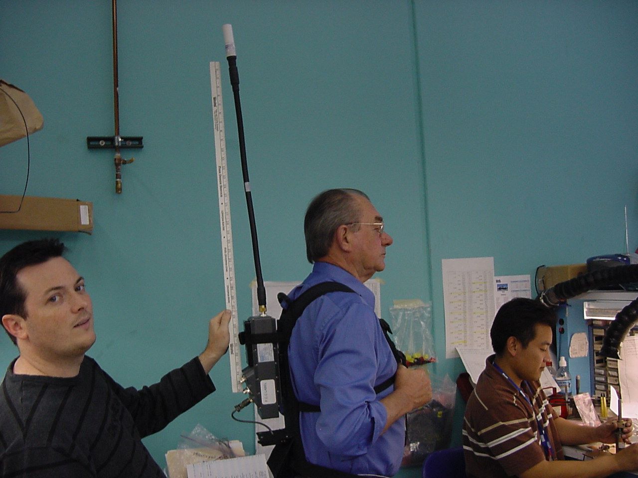
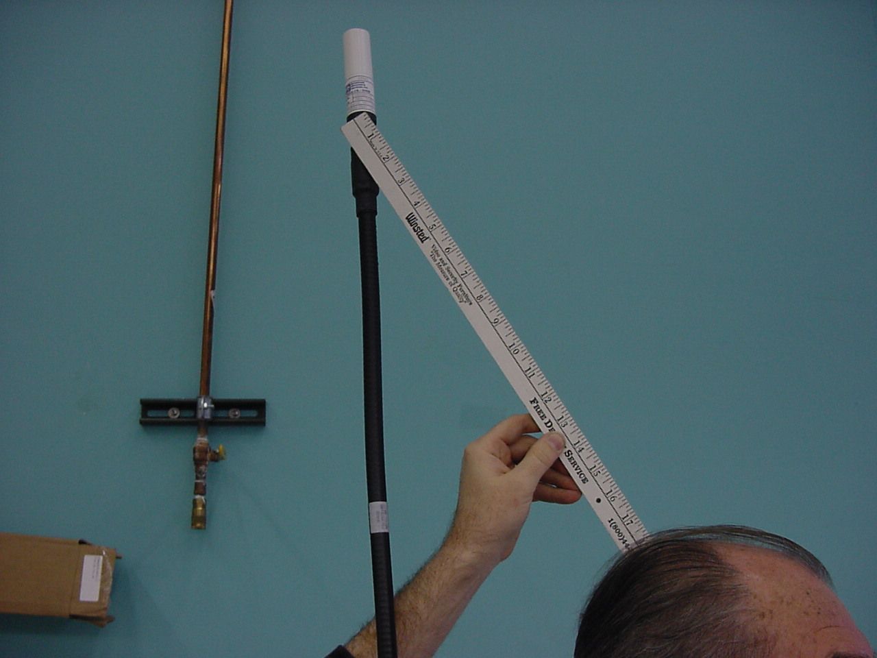
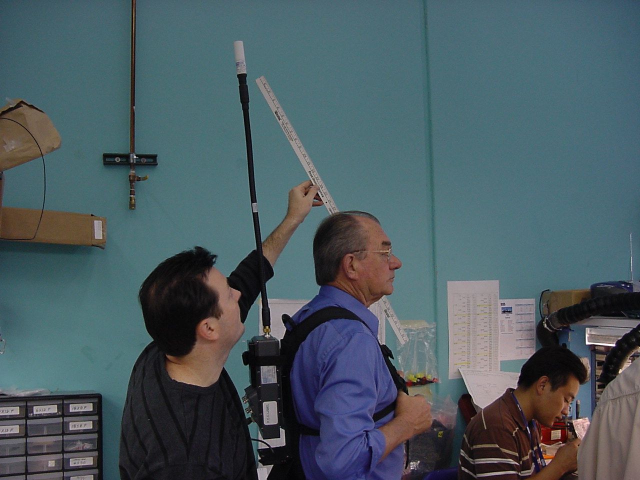
Prediction of MPE limit at a given distance Equation from page 18 of OET Bulletin 65, Edition 97-01where: S = power density P = power input to the antennaG = power gain of the antenna in the direction of interest relative to an isotropic radiatorR = distance to the center of radiation of the antenna Maximum peak output power at antenna input terminal: 34.00 (dBm) Maximum peak output power at antenna input terminal: 2511.886432 (mW) Antenna gain(typical): 2 (dBi) Maximum antenna gain: 1.584893192 (numeric) Prediction distance: 20 (cm) Prediction frequency: 3458 (MHz) MPE limit for uncontrolled exposure at prediction frequency: 1 (mW/cm^2) Power density at prediction frequency: 0.792009 (mW/cm^2) Maximum allowable antenna gain: 3.012698554 (dBi) Margin of Compliance: 1.012698554 The output emission is separated b y the user as he wears the backpack radio b y a coax extention that keeps the antenna more than 20 cm from the user's head. This extention and antenna is built as onepiece unit and the user is warned in the user's manual not to change this configuration. 2 4 R PG S π =
Test Report
Nemko USA, Inc. Phone (858) 755-5525 Fax (858) 452-1810 11696 Sorrento Valley Rd., Suite F San Diego, CA 92121-1024 Master: FCC Part22HCSU Date February 13, 2002 Test Report: 2004 110516 FCC Applicant: Broadcast Microwave Services 12367 Crosthwaite Circle Dock 10 Poway, CA 92064 858-391-3050 858-391-3049- fax Equipment Under Test: Model: CCII-7 Transmitter FCC ID: CNVCCII-7-D In Accordance With: FCC PART 2, FCC PART 74.637, PART 90.209 Tested By: Nemko USA Inc. 11696 Sorrento Valley Road San Diego, CA 92121-1024 Date: 1-24-05 Total Number of Pages: 39 Nemko USA Inc. EQUIPMENT: Transmitter CCII-7 REPORT NO.: 2004 110516 FCC Table of Contents Section 1. Summary of Test Results...................................................................................3 Section 2. General Equipment Specification......................................................................6 Section 3. RF Power Output................................................................................................7 Section 4. Modulation Characteristics..............................................................................8 Section 5. Occupied Bandwidth........................................................................................12 Section 6. Spurious Emissions At Antenna Terminals.....................................................16 Section 7. Field Strength of Spurious................................................................................26 Section 8. Test Equipment List..........................................................................................28 Page 2 of 39 Nemko USA Inc. EQUIPMENT: Transmitter CCII-7 REPORT NO.: 2004 110516 FCC Section 1. Summary of Test Results General All measurements are traceable to national standards. These tests were conducted on a sample of the equipment for the purpose of demonstrating compliance with FCC Part 22, Subpart H. DOCUMENT HISTORY REVISION DATE COMMENTS - 11-30-04 Prepared By: A. Laudani - 1-24-05 Initial Release: R. L. Hill NOTE: Nemko USA, Inc. hereby makes the following statements so as to conform to Chapter 10 (Test Reports) Requirements of ANSI C63.4 (1992) “Methods and Measurement of Radio- Noise Emissions from Low-Voltage Electrical and Electronic Equipment in the Range of 9 kHz to 40 GHz”: o The unit described in this report was received at Nemko USA, Inc.'s facilities on November 17, 2004. Testing was performed on the unit described in this report on November 17, 2004 to November 24, 2004 . o The Test Results reported herein apply only to the Unit actually tested, and to substantially identical Units. o This report does not imply the endorsement of the Federal Communications Commission (FCC), NVLAP or any other government agency. This Report is the property of Nemko USA, Inc., and shall not be reproduced, except in full, without prior written approval of Nemko USA, Inc. However, all ownership rights are hereby returned unconditionally to Broadcast Microwave Services, and approval is hereby granted to Broadcast Microwave Services and its employees and agents to reproduce all or part of this report for any legitimate business purpose without further reference to Nemko USA, Inc. Page 3 of 39 Nemko USA Inc. EQUIPMENT: Transmitter CCII-7 REPORT NO.: 2004 110516 FCC CERTIFICATION Nemko USA, Inc., an independent Electromagnetic Compatibility (EMC) Test Laboratory, produced this Test Report and performed the Radio Frequency Interference (RFI) testing and data evaluation contained herein. Nemko USA, Inc.’s measurement facility is currently registered with the United States Federal Communications Commission (FCC) in accordance with the provisions of 47 United States Code (CFR) Part 2, Subpart I, Section 2.948(a). A current description of Nemko USA, Inc.’s measurement facility is on file with the FCC. Nemko USA Inc. has additionally satisfied the FCC that it complies with the requirements set forth in 47 CFR Part 2, Subpart I, Section 2.948(d) regarding the accreditation of EMC laboratories. As a result, the FCC has placed Nemko USA Inc. on its list of EMC laboratories approved to perform Declaration of Conformity (DOC) procedure testing. The RFI testing, test data collection and test data evaluation were accomplished in accordance with the ANSI C63.4-1992 Standard, and in accordance with the applicable sections of the FCC rules (47 CFR Parts 2 and 18)." digital devices. The testing was also accomplished in accordance with Industry Canada's ICES-003 standard for unintentional radiating device per EMCAB-3, Issue 3 (May 1998). The administrative summary of this test report provides a description of the test sample I hereby certify that the test data, test data evaluation, and equipment configurations used to compile this test report are a true and accurate representation of the test sample’s radio frequency interference characteristics as of the test date(s), and, for the design of the test sample. ________________________________ Ricky L. Hill, Senior EMC Test Engineer Page 4 of 39 Nemko USA Inc. EQUIPMENT: Transmitter CCII-7 REPORT NO.: 2004 110516 FCC Summary Of Test Data Name Of Test Para. No. Result RF Power Output 2.1046 PASS Modulation Characteristics 2.1047 AS REPORTED Occupied Bandwidth 2.1049 PASS Spurious Emissions at Antenna Terminals 2.1051 PASS Field Strength of Spurious Emissions 2.1053 PASS Frequency Stability 2.1055 PASS Footnotes For N/A’s: EUT is a digitally modulated transmitter. Parts 74 and 90 do not express limits or pass/fail criteria for Modulation Characteristics. Test Conditions: Indoor Temperature: ___19--22 _°C Humidity: ___40-50 __% Outdoor Temperature: ___15--24 _°C Humidity: ___40-50 __% . Page 5 of 39 Nemko USA Inc. EQUIPMENT: Transmitter CCII-7 REPORT NO.: 2004 110516 FCC Section 2. General Equipment Specification Manufacturer: Broadcast Microwave Services Model No.: CCII & CDII (Transmitter and Receiver) Serial No.: 226-31704 Date Received In Laboratory: November 17, 2004 Nemko Identification No.: 24…
Text truncated - open the document above for the full version.
Test Setup Photos
Para. No. 2.1051 Spurious Emissions at Antenna Terminals Para. No. 2.1049 - Occupied Bandwidth Para. No. 2.1046 - R.F. Power Output EUTAttenuator Radio Communication Monitor Spectrum Analyzer Para. No. 2.1055 - Frequency Stability Climate Chamber EUT Variable Power Supply Attenuator Frequency Counter Para. No. 2.1053 - Field Strength of Spurious Radiation 3 METERS EUT NON-CONDUCTING TURN-TABLE 0.8 METER VARIABLE SEARCH HEIGHT (1 TO 4 m) TO TEST RECEIVER/SPECTRUM ANALYZER SEARCH ANTENNA
Contact Information
Applicant
Graham Bunney(President)
Technical Contact
Nemko USAAlan Laudani
[email protected]858-755-5525
11696 Sorrento Valley Road · San Diego, California · United States
Test Firm
Nemko USA, Inc.Rhonda Saxon
Technical Specifications
| # | Rule Parts | Frequency Range | Power Output | Emission | Tolerance |
|---|---|---|---|---|---|
| 2 | 9 | 1.99 GHz - 2.50 GHz | 4.1 W | 9M00W7D | 221 Hz |
Other Applications from Broadcast Microwave Services Inc
CNVHC4-6L
Aug 13, 2014Transmitter
Equipment Class
TNB - Licensed Non-Broadcast Station Transmitter
CNVHC4-2
Mar 19, 2014Heli-Coder 4 Transmitter
Equipment Class
TNB - Licensed Non-Broadcast Station Transmitter
CNVHCII-5-7
Mar 06, 20082 GHz RF Power Amplifier
Equipment Class
AMP - Amplifier
CNVHCII-7
Mar 06, 20082 GHz RF Power Amplifier
Equipment Class
AMP - Amplifier
CNVTCII-ODU-9
Aug 08, 20077 GHz Truck Coder II
Equipment Class
TNB - Licensed Non-Broadcast Station Transmitter