CNVTCII-ODU-97 GHz Truck Coder II
Broadcast Microwave Services Inc
Click to zoom
Application Details
- Equipment Class
- TNB - Licensed Non-Broadcast Station Transmitter
- Date of Grant
- Aug 08, 2007
- Application Purpose
- Original Equipment
- Date of Application
- Aug 08, 2007
- Equipment Note
- 7 GHz Truck Coder II
- Frequency Range
- 6875.00000000 - 7125.00000000
- Country
- United States
Documents & Files
Document Text
Text extracted from the exhibit documents filed with the FCC. Open a document above to read the original.
Users Manual
Installation and Operations Manual 7GHz Truck Coder II System DOC# 6051419100X3 July 2006 Broadcast Microwave Services, Inc. 12367 Crosthwaite Circle Poway, CA 92064 800-669-9667, 858-391-3050 858-391-3049 FAX This Page Intentionally Left Blank INTRODUCTION The BMS Truck-Coder II (TCII) is an ENG transmitter that operates in both digital (COFDM) and legacy analog (FM) transmission modes. It features a DVB-T compliant (COFDM) modulator MPEG2 video encoder. The system is designed to support both 12 MHz and 17 MHz BAS channel plans (in both Digital and FM transmission modes). The two-unit system consists of an Indoor rack-mounted exciter Unit (IDU) and an Outdoor mast-mounted RF Transmitter Unit (ODU). An optional second RF unit can be added to support dual band operation. The system integrates support for mast mounted antenna relay, feed controls and other accessories. The indoor unit provides support for multiple analog and video signal formats and provides an industry standard 70MHz IF output. The Truck-Coder II is designed to meet the rugged environmental needs of ENG news vehicles. It blends our field proven technology with a rich feature set and the simple operation needed for ENG/OB operations. Applications: • ENG News Vehicles • Law Enforcement Command Posts Key Features: • Digital (COFDM) and Analog (FM) Transmission • Ease of installation – a single coax cable interconnects the IDU and ODU • Simple Set-up and Operation – menu driven user interface • Up to 999 easily configurable user Presets (each capable of storing all system parameters) • Front panel Ethernet Port simplifies firmware upgrades and supports web based management • Fully configurable FM, COFDM and MPEG parameters (including PID’s) ensure product compatibility • Optional Dual Band Capability This document provides instructions for the installation, operation and maintenance of the Truck Coder II system. Broadcast Microwave Services (BMS) is a leader in wireless digital microwave technology providing innovative products for the television broadcast, video, telemetry and surveillance industries. A wholly owned subsidiary of Cohu, Inc., BMS designs and manufactures a comprehensive line of microwave communications equipment for broadcasting sports venues, law enforcement and military applications. BMS also builds and integrates command and control centers to provide fully functioning, complex, end to end digital systems. For the latest product and system information please visit www.bms-inc.com . Broadcast Microwave Services, Inc. 12367 Crosthwaite Circle Poway, CA 92064 Tel: +1 (858) 391-3050 Toll free (US): 800-669-9667 Fax: +1 (858) 391-3049 Email:[email protected] Web: www.bms-inc.com ii This Page Intentionally Left Blank iii Table of Contents INTRODUCTION........................................................................................................................................... i SYSTEM DESCRIPTION ............................................................................................................................. 1 Overview.................................................................................................................................................... 1 Indoor Unit................................................................................................................................................. 2 Outdoor Unit .............................................................................................................................................. 4 Technical Specifications ............................................................................................................................ 5 UNPACKING ................................................................................................................................................ 9 Parts List .................................................................................................................................................... 9 Manuals ................................................................................................................................................. 9 Components ........................................................................................................................................... 9 Cables .................................................................................................................................................... 9 INSTALLATION ......................................................................................................................................... 11 Equipment Installation ............................................................................................................................. 11 Installing the Indoor Unit (IDU) .......................................................................................................... 15 Indoor Unit (IDU) Connections ........................................................................................................... 17 Installing the Outdoor Unit (ODU)...................................................................................................... 18 OPERATION ............................................................................................................................................... 22 Initialization ............................................................................................................................................. 22 WARRANTY ............................................................................................................................................... 25 Customer Service Information ................................................................................................................. 25 TROUBLE SHOOTING .............................................................................................................................. 27 Diagnostics...............…
Text truncated - open the document above for the full version.
External Photos
-front view 85 –265 VAC 2 AMP ASI WARNING 48 VDC PRESENT ON THIS CONNECTOR 70 MHz/ 48 VDC/ TM OUT OFFON 48 VDC AUXILIARY INPUTS SUMMARY ALARM OUTIN OUTIN AUDIO2 INAUDIO1 IN SDI IN W/ AUDIO VIDEO IN RS-232 DCE TELEMETRY RS- 232 CONTROL RS- 232 AUX DATA 10/100 ETHERNET 70 MHz FCC ID LABEL -rear view
ID Label/Location Info
Broadcast Microwave Services Inc. Made In USA FCC ID : CNVTCII-ODU-9 Model No: TCII-ODU-9 Sample FCC ID Label for 7 GHz Truck-Coder II Dimensions: 2.5" x 0.5"
ID Label/Location Info
85 –265 VAC 2 AMP ASI WARNING 48 VDC PRESENT ON THIS CONNECTOR 70 MHz/ 48 VDC/ TM OUT OFFON 48 VDC AUXILIARY INPUTS SUMMARY ALARM OUTIN OUTIN AUDIO2 INAUDIO1 IN SDI IN W/ AUDIO VIDEO IN RS-232 DCE TELEMETRY RS- 232 CONTROL RS- 232 AUX DATA 10/100 ETHERNET 70 MHz FCC ID LABEL
Internal Photos
Truck-Coder II Indoor Unit (IDU) 8014191000 Digital Board Assembly 7214206010 Digital Board 7214206900 MPEG Encoder Board 598007001 Digital Board Power Supply 7214215000 IDU IF Board Assembly 7214191000 CPU Board 598010000 Front Panel 5V Power Supply 12V Power Supply Digital Board Assembly Digital Board Power Supply 48V Power Supply Fan CPU IDU-IF Board (under the Digital Board) 5V Power Supply 12V Power Supply Digital Board Assembly Digital Board Power Supply 48V Power Supply Fan CPU IDU-IF Board Front View Rear View Digital Board MPEG Encoder Front View Rear View Front View Rear View Front View Rear View Front View Rear View
Internal Photos
ODU System ODU Unit: 8014192700 ODU RFU: 7214233000 ODU PA: 7214232000 ODU IFU: 7214192010 ODU PS: 7214212000 ODU AO: 7214209000 DCR Board IFU Board AUX Board RFU BoardPA Board Front view Rear view Front view Rear view Front view Rear view Front view Rear view Front view Rear view
Operational Description
Broadcast Microwave Services Inc. 12367 Crosthwaite Circle, Poway, CA 92064-6817 Phone: 858-391-3050. Toll Free: 800-669-9667. Fax: 858-391-3049. Web: www.bms-inc.com EQUIPMENT The 7GHz Truck-Coder II (TCII) is a non-broadcast mobile transmitter for use in the frequency range of 6425 MHz to 7125 MHz. This product supports the following Emission Designators: FCC ID Modulation Emission Designators CNVTCII-ODU-9 Digital 6M00W7D 7M00W7D 8M00W7D CNVTCII-ODU-9 Analog 15M0F8W Operation under FCC rule parts: 74 APPLICATION Truck-Coder II is designed for use in ENG News Vehicles (rule part 74). The TCII supports transmission of video, audio, and data. OPERATION The TCII operates in both digital (COFDM) and legacy analog (FM) transmission modes. It features a DVB-T compliant (COFDM) modulator MPEG2 video encoder. The system is designed to support the existing 25MHz BAS channel plans (in both Digital and FM transmission modes). For BAS application the entire frequency range (6425MHz to 7125MHz) is divided by two sub-bands: the low-band (6425MHz – 6525MHz) and the high band (6875MHz – 7125MHz). The 7GHz TCII is operable over 4 x 25MHz channels on the low-band and 10 x 25MHz channels on the high band respectively. Figure 1 shows a symbolic diagram of the 7GHz Truck-Coder system. The two-unit system consists of an Indoor rack-mounted exciter Unit (IDU) and an Outdoor mast-mounted RF Transmitter Unit (ODU). An optional second RF unit can be added to support dual band operation. The Indoor Unit (located inside the vehicle) produces 70 MHz IF signal by modulating the input video, audio, and or data. The IDU supports multiple analog and video signal formats and provides an industry standard 70MHz IF output. The IF signal is transferred through a long coaxial cable to the Outdoor Unit (ODU) located on the antenna mast. The antenna mast is an foldable structure on the vehicle rooftop. The mast supports the ODU, the transmitter antenna as well as the feed assembly as shown symbolically in Figure 1. Broadcast Microwave Services Inc. 12367 Crosthwaite Circle, Poway, CA 92064-6817 Phone: 858-391-3050. Toll Free: 800-669-9667. Fax: 858-391-3049. Web: www.bms-inc.com Inside Vehicle Indoor Unit (IDU) Vehicle Rooftop 85 – 265 VAC 2 AMP ASI WARNING 48 VDC PRESENT ON THIS CONNECTOR 70 MHz/ 48 VDC/ TM OUT OFFON 48 VDC AUXILIARY IN PU TS SUMMARY ALARM OUTIN OUTIN AUDIO2 INAUDIO1 IN SDI IN W / AUDIO VIDEO IN RS- 232 DCE TELEMETRY RS- 232 CONTROL RS- 232 AUX DATA 10/ 100 ETHERNET 70 MHz Front Rear Long Coaxial Cable Outdoor Unit (ODU) Adjustable Mast Transmitter Antenna IF In RF Out 6.425 – 7.125 GHz 70 MHz Figure 1 Symbolic diagram of the 7GHz Truck-Coder II Assembly The ODU converts the 70 MHz IF signal into the final RF frequency within the 6.425 GHz to 7.125 GHz range. The output RF is directly fed to the antenna.
Operational Description
ENG Video Camera CCII Portable Transmitter Omni Antenna Local Receive Antenna From Camera to Truck F r o m T r u c k t o t h e T e l e v i s i o n S t u d i o 2GHz BAS Transmission 7 G H z B A S T r a n s m i s s i o n 7GHz Truck-Coder II (Outdoor Unit) 7GHz Truck-Coder II (Intdoor Unit) Ant. Cable Transmitting Antenna ENG* Truck (*) ENG: Electronic News Gathering PPLICATION OFZRUCKODERFOR TRANSMITTING NEWS TELEVISION SIGNAL FROM THE EVENT SITE TO THE STUDIO
Operational Description
The 7GHz Truck-Coder II is designed for Broadcast Auxiliary Services (BAS) application.The product is used to transmit visual program material between the remote pickup station (at the news event) and the television studio. According to FCC Part 74.631, among the various applications in the BAS category, the closest that the product fits in is: TV Intercity Relay Station. The attached pdf file illustrates the application of the 7GHz Truck- Coder II in the TV relay station with more details. According to the drawing, the news television signal is picked up by the local TV camera and is sent to the ENG truck by the 2GHz portable BAS transmitter (Cary-Coder II). Once the signal is picked up by the rooftop receiving antenna, it will be directed to the 7GHz Truck-Coder II indoor unit wher the it is downconverted to the 70MHz IF signal. The IF signal will then fed to the 7GHz Truck-Coder II outdoor unit (located on the roof-top mast). The outdoor unit will upconvert the IF into the 7GHz signal which will be transmitted to the TV studio.
RF Exposure Info
1 WARNING! RF RADIATION EXPOSURE HAZARD This warning is provided by Broadcast Microwave Services (BMS) Inc. for safety purpose. The following information help to reduce the risk of RF exposure hazard. FCC Limit of RF Exposure According to Federal Communication Commission (FCC), the Maximum Permissible Exposure (MPE) for FR radiation has been set to 1.0 mW/cm 2 for the 7GHz Truck- Coder II equipment (OET Bulletin 65). The 7GHz Truck-Coder II is a non-broadcast transmitter and without an antenna it will not create RF exposure (power density) exceeding the 1.0 W/cm 2 FCC limit. However a high-gain antenna such as a parabolic dish will greatly enhance the Field- Coder II output power density beyond the MPE limit of 1.0 mW/cm 2 . In this situation a minimum distance from the antenna needs to be calculated in order to keep the MPE always below the safety limit. The calculation has been done for Field- Coder II based on the formula mentioned in OET Bulletin 56. The calculations have been done for different commonly used antenna in Electronic New Gathering (ENG) systems. Digital Transmission Figure 1 shows the plot of the minimum exposure distance for 0dBi, 5dBi, 16dBi, and 30dBi antennas. The 7GHz Truck-Coder II transmits the maximum power of 4 Watts. The minimum exposure distances are found from the cross points of the exposure graphs (for various antennas) with the line of maximum permissible exposure (i.e. 1 W/cm 2 ). Notice that the numbers in Figure 1 predict the worse case scenario, which is straight in front of the antenna (exposing to the antenna main-lobe). Obviously the side- lobe exposures are well below these numbers as the radiation intensity dramatically reduces on the side lobes. The antenna used for this transmitter must not be co-located or operating in conjunction with any other antenna or transmitter. 2 Estimated RF Exposure for 7 GHz Truck-Coder II 0.0 1.0 2.0 3.0 4.0 5.0 0100200300400500600700 Dis tance , cm Power Density, mW/cm^2 Max Permissible Exposure: 1mW/cm 2 30 dBi Antenna Max Exposure at 560 cm 0 dBi Antenna Max Exposure at 20 cm 16 dBi Antenna Max Exposure at 112 cm 5 dBi Antenna Max Exposure at 35 cm Figure 1 Summary In order the keep the RF exposure within the FCC limit, it is necessary to maintain the safe distance from the antenna. The results shown in Figures 1 can be summarized in the following table: Minimum permissible distance from antenna (cm) Antenna Gain (dBi) 0 20 5 35 16 112 30 560 Notice the above table indicates worst-case situation (straight in front of the antenna).
Test Report
Nemko USA, Inc. Phone (858) 755-5525 Fax (858) 452-1810 11696 Sorrento Valley Rd., Suite F San Diego, CA 92121-1024 Test Report: 2007 065455 FCC Applicant: Broadcast Microwave Services 12367 Crosthwaite Circle Dock 10 Poway, CA 92064 (858) 391-3050 x147 (858) 391-3049 - fax Equipment Under Test: Model: 7GHz Truck-Coder II (TCII) Van Microwave System FCC ID: CNVTCII-ODU-9 In Accordance With: FCC PART 2 and FCC PART 74 Subpart F Tested By: Nemko USA Inc. 11696 Sorrento Valley Road San Diego, CA 92121-1024 Date: July 31, 2007 Total Number of Pages: 81 Nemko USA Inc. EQUIPMENT: 7GHz Truck-Coder II (TCII) REPORT NO.: 2007 065455 FCC FCC ID: CNVTCII-ODU-9 Page 2 of 81 DOCUMENT HISTORY REVISION DATE COMMENTS - July 31, 2007 Prepared By: F.S.Custodio - July 31, 2007 Initial Release: A.A. Laudani NOTE: Nemko USA, Inc. hereby makes the following statements so as to conform to Chapter 10 (Test Reports) Requirements of ANSI C63.4: 2003 “Methods and Measurement of Radio-Noise Emissions from Low-Voltage Electrical and Electronic Equipment in the Range of 9 kHz to 40 GHz”: o The unit described in this report was received at Nemko USA, Inc.'s facilities on June 12, 200. Testing was performed on the unit described in this report on June 12, 2007 to July 31, 2006. o The Test Results reported herein apply only to the Unit actually tested, and to substantially identical Units. o This report does not imply the endorsement of the Federal Communications Commission (FCC), NVLAP or any other government agency. This Report is the property of Nemko USA, Inc., and shall not be reproduced, except in full, without prior written approval of Nemko USA, Inc. However, all ownership rights are hereby returned unconditionally to Broadcast Microwave Services, and approval is hereby granted to Broadcast Microwave Services and its employees and agents to reproduce all or part of this report for any legitimate business purpose without further reference to Nemko USA, Inc. Nemko USA Inc. EQUIPMENT: 7GHz Truck-Coder II (TCII) REPORT NO.: 2007 065455 FCC FCC ID: CNVTCII-ODU-9 Page 3 of 81 Table of Contents Section 1. Summary of Test Results.................................................................................5 Section 2. General Equipment Specification..................................................................6 Section 3. RF Power Output................................................................................................7 Section 4. Modulation Characteristics............................................................................12 Section 5. Occupied Bandwidth.......................................................................................17 Section 6. Spurious Emissions At Antenna Terminals..............................................22 Section 7. Field Strength of Spurious.............................................................................58 Section 8. Frequency Stability..........................................................................................60 Section 9. Test Equipment List.........................................................................................63 APPENDICES Appendix A. Spurious Emissions At Antenna Terminals..............................................64 Nemko USA Inc. EQUIPMENT: 7GHz Truck-Coder II (TCII) REPORT NO.: 2007 065455 FCC FCC ID: CNVTCII-ODU-9 Page 4 of 81 CERTIFICATION Nemko USA, Inc., an independent Electromagnetic Compatibility (EMC) Test Laboratory, produced this Test Report and performed the Radio Frequency Interference (RFI) testing and data evaluation contained herein. Nemko USA, Inc.’s measurement facility is currently registered with the United States Federal Communications Commission (FCC) in accordance with the provisions of 47 United States Code (CFR) Part 2, Subpart I, Section 2.948(a). A current description of Nemko USA, Inc.’s measurement facility is on file with the FCC. Nemko USA Inc. has additionally satisfied the FCC that it complies with the requirements set forth in 47 CFR Part 2, Subpart I, Section 2.948(d) regarding the accreditation of EMC laboratories. As a result, the FCC has placed Nemko USA Inc. on its list of EMC laboratories approved to perform Declaration of Conformity (DOC) procedure testing. The RFI testing, test data collection and test data evaluation were accomplished in accordance with the ANSI C63.4: 2003 Standard, and in accordance with the applicable sections of the FCC rules (47 CFR Parts 2 and 18)." digital devices. The testing was also accomplished in accordance with Industry Canada's ICES-003 standard for unintentional radiating device per EMCAB-3, Issue 3 (May 1998). The administrative summary of this test report provides a description of the test sample I hereby certify that the test data, test data evaluation, and equipment configurations used to compile this test report are a true and accurate representation of the test sample’s radio frequency interference characteristics as of the test date(s), and, for the design of the test sample. Alan A. Laudani, EMC Test Engineer Nemko USA Inc. EQUIPMENT: 7GHz Truck-Coder II (TCII) REPORT NO.: 2007 065455 FCC FCC ID: CNVTCII-ODU-9 Page 5 of 81 Section 1. Summary of Test Results General All measurements are traceable to national standards. These tests were conducted on a sample of the equipment for the purpose of demonstrating compliance with FCC PART 2 and FCC PART 74 Subpart F. Summary Of Test Data Name Of Test Para. No. Result RF Power Output 2.1046 PASS Modulation Characteristics 2.1047 AS REPORTED Occupied Bandwidth 2.1049 PASS Spurious Emissions at Antenna Terminals 2.1051 PASS Field Strength of Spurious Emissions 2.1053 PASS Frequency Stability 2.1055 PASS Footnotes for 2.1047: EUT is a digitally modulated transmitter. Parts 74 do not express limits or pass/fail criteria for Modulation Characteristics. Test Conditions: Indoor Temperature: 23.3 °C Humidity: 47-58 % Outdoor Temperature: 23 °C Humidity: 55 % . Nemko USA Inc. EQUIPMENT: 7GHz …
Text truncated - open the document above for the full version.
Test Report
Document type: Engineering Test Report File name: FCC Cert. -- Audio Response.doc Doc # : none Revision: -- Page 1 of 11 This document contains proprietary information. Disclosure to others, use, or copying without the express written authorization of Broadcast Microwave Services, Inc. is strictly prohibited. Truck Coder II Audio Response Measurement for FCC Type Certification Revision: -- Date: 2/20/2007 Document Number: none Title: IDU Audio Response Measurement Author: L Greenbank Document title: IDU Audio Response Measurement Doc # : none Revision: -- Page 2 of 11 This document contains proprietary information. Disclosure to others, use, or copying without the express written authorization of Broadcast Microwave Services, Inc. is strictly prohibited. Revision History Date Author Description of changes Revision 2/20/2007 L Greenbank Initial release -- L Greenbank Table of Contents 1. Introduction .........................................................................................3 2. Scope..................................................................................................3 3. Definitions ...........................................................................................3 4. References..........................................................................................3 5. Equipment...........................................................................................4 6. Test Procedures..................................................................................4 6.1. Audio Gain..............................................................................................5 6.1.1. Setup ...............................................................................................5 6.1.2. Measurement Data ..........................................................................6 6.1.3. Gain plot (peak deviation)................................................................6 6.2. Audio Frequency Response ...................................................................7 6.2.1. Setup ...............................................................................................7 6.2.2. Measurement Data ..........................................................................8 6.2.3. Plot of Frequency Response ...........................................................9 7. Appendix .............................................................................................9 7.1. Supplemental plots--Layout view ............................................................9 Document title: IDU Audio Response Measurement Doc # : none Revision: -- Page 3 of 11 This document contains proprietary information. Disclosure to others, use, or copying without the express written authorization of Broadcast Microwave Services, Inc. is strictly prohibited. 1. Introduction This document records the audio frequency response of the Truck Coder II up to and including the Subcarrier generation, in response to the TCB review at NEMCO, Canada. ........ 2. Scope Most of the type certification data was taken by NEMCO. This additional audio measurement data was taken at BMS to supplement the application for type certification. It includes audio gain and frequency response in analog mode for the two rear panel audio inputs on the IDU of the Truck Coder II system. 3. Definitions Term Definition ODU Outdoor Unit IDU Indoor Unit BW Bandwidth FM Frequency Modulation OFDM Orthogonal Frequency Division Multiplex TCII Truck Coder II BMS Broadcast Microwave Services FCC Federal Communications Commission TCB Type Certification Board NEMCO 4. References [1] 47 CFR Part 2, July, 1998 § 2.1047 Measurements required: Modulation characteristics. (a) Voice modulated communication equipment. A curve or equivalent data showing the frequency response of the audio modulating circuit over a range of 100 to 5000 Hz shall be submitted. For equipment required to have an audio low-pass filter, a curve showing the frequency response of the filter, or of all circuitry installed between the modulation limiter and the modulated stage shall be submitted. (b) Equipment which employs modulation limiting. A curve or family of curves showing the percentage of modulation Document title: IDU Audio Response Measurement Doc # : none Revision: -- Page 4 of 11 This document contains proprietary information. Disclosure to others, use, or copying without the express written authorization of Broadcast Microwave Services, Inc. is strictly prohibited. versus the modulation input voltage shall be supplied. The information submitted shall be sufficient to show modulation limiting capability throughout the range of modulating frequencies and input modulating signal levels employed. (c) Single sideband and independent sideband radiotelephone transmitters which employ a device or circuit to limit peak envelope power. A curve showing the peak envelope power output versus the modulation input voltage shall be supplied. The modulating signals shall be the same in frequency as specified in paragraph (c) of § 2.1049 for the occupied bandwidth tests. (d) Other types of equipment. A curve or equivalent data which shows that the equipment will meet the modulation requirements of the rules under which the equipment is to be licensed. [39 FR 5919, Feb. 15, 1974. Redesignated and amended at 63 FR 36599, July 7, 1998] 5. Equipment [1] Agilent HP8903A Audio Analyzer [2] Agilent HP8901A Modulation Analyzer [3] Ballantine 323 True RMS AC voltmeter 6. Test Procedures Standard production test procedures and test data sheets were reviewed and compiled for this report. A random sample of three units are reported. All IDUs are 100% tested for gain and frequency response. Each channel was tested separately with sine inputs into the rear panel of the IDU. The FM audio subcarriers were sampled at Test points provided within the IDU, and demodulated by test equipment. Gain was measured as the peak FM deviation due to a fixed audio input vo…
Text truncated - open the document above for the full version.
Test Setup Photos
FCC ID: CNVTCII-ODU-9 6 & 7 GHz Truck-Coder FCC ID: CNVTCII-ODU-9 6 & 7 GHz Truck-Coder FCC ID: CNVTCII-ODU-9 6 & 7 GHz Truck-Coder
Contact Information
Applicant
Graham Bunney(President)
Technical Contact
BMS Inc.Ali Sayyah
[email protected](858) 391-3050
12367 Crosthwaite Circle · Poway, California · United States
Non-Technical Contact
BMS Inc.David Woodhead
[email protected](858) 391-3050
Test Firm
Nemko USA, Inc.Rhonda Saxon
Technical Specifications
| # | Rule Parts | Frequency Range | Power Output | Emission | Tolerance |
|---|---|---|---|---|---|
| 8 | 74 | 6.88 GHz - 7.13 GHz | 2.8 W | 11M3F8W | 1.41 ppm |
Other Applications from Broadcast Microwave Services Inc
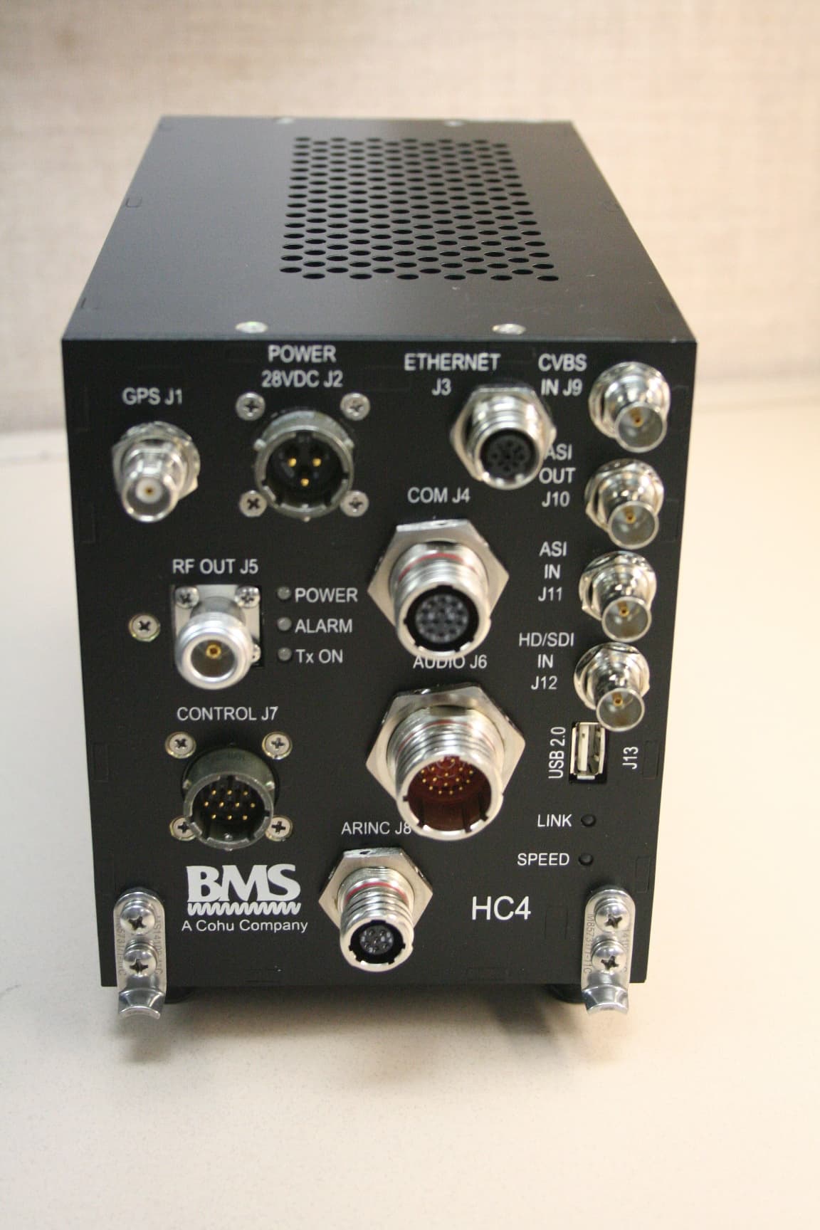
CNVHC4-6L
Aug 13, 2014Transmitter
Equipment Class
TNB - Licensed Non-Broadcast Station Transmitter
CNVHC4-2
Mar 19, 2014Heli-Coder 4 Transmitter
Equipment Class
TNB - Licensed Non-Broadcast Station Transmitter
CNVHCII-5-7
Mar 06, 20082 GHz RF Power Amplifier
Equipment Class
AMP - Amplifier
CNVHCII-7
Mar 06, 20082 GHz RF Power Amplifier
Equipment Class
AMP - Amplifier
CNVHCII-9
Jul 22, 20076 GHz Power Amplifier
Equipment Class
AMP - Amplifier