CWU-SAA596803SAA5968-03
AMX LLC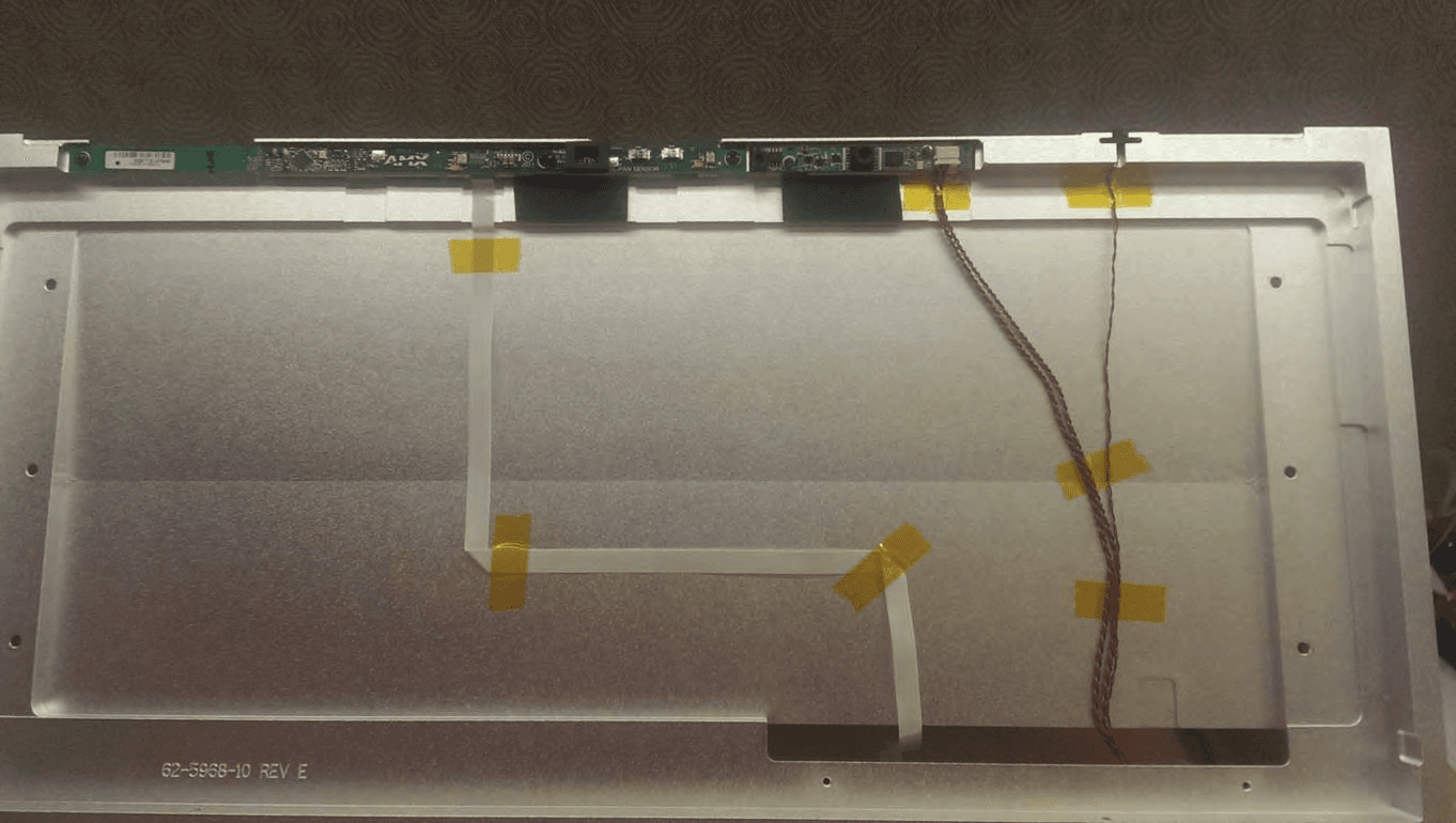
Click to zoom
Application Details
- Equipment Class
- DXX - Part 15 Low Power Communication Device Transmitter
- Date of Grant
- Sep 17, 2015
- Application Purpose
- Original Equipment
- Date of Application
- Sep 17, 2015
- Equipment Note
- SAA5968-03
- Frequency Range
- 13.56000000 - 13.56000000
- Company
- AMX LLC
- Country
- United States
Documents & Files
Document Text
Text extracted from the exhibit documents filed with the FCC. Open a document above to read the original.
Users Manual
INSTALLATION & HARDWARE REFERENCE MANUAL MODERO X ® SERIES G5 TOUCH PANELS MXT-2001-PAN 20.3" MODERO X SERIES G5 PANORAMIC TABLETOP TOUCH PANEL MXD-2001-PAN-L 20.3" MODERO X SERIES G5 PANORAMIC LANDSCAPE WALL MOUNT TOUCH PANEL MXD-2001-PAN-P 20.3" MODERO X SERIES G5 PANORAMIC PORTRAIT WALL MOUNT TOUCH PANEL MXT-1901-PAN 19.4" MODERO X SERIES G5 PANORAMIC TABLETOP TOUCH PANEL MXD-1901-PAN-L 19.4" MODERO X SERIES G5 PANORAMIC LANDSCAPE WALL MOUNT TOUCH PANEL MXD-1901-PAN-P 19.4" MODERO X SERIES G5 PANORAMIC PORTRAIT WALL MOUNT TOUCH PANEL MXT-1001 10.1" MODERO X SERIES G5 TABLETOP TOUCH PANEL MXD-1001-L 10.1" MODERO X SERIES G5 LANDSCAPE WALL MOUNT TOUCH PANEL MXD-1001-P 10.1" MODERO X SERIES G5 PORTRAIT WALL MOUNT TOUCH PANEL MXT-701 7" MODERO X SERIES G5 TABLETOP TOUCH PANEL MXD-701-L 7" MODERO X SERIES G5 LANDSCAPE WALL MOUNT TOUCH PANEL MXD-701-P 7" MODERO X SERIES G5 PORTRAIT WALL MOUNT TOUCH PANEL IMPORTANT SAFETY INSTRUCTIONS COPYRIGHT NOTICE AMX© 2015, all rights reserved. No part of this publication may be reproduced, stored in a retrieval system, or transmitted, in any form or by any means, electronic, mechanical, photocopying, recording, or otherwise, without the prior written permission of AMX. Copyright protection claimed extends to AMX hardware and software and includes all forms and matters copyrightable material and information now allowed by statutory or judicial law or herein after granted, including without limitation, material generated from the software programs which are displayed on the screen such as icons, screen display looks, etc. Reproduction or disassembly of embodied computer programs or algorithms is expressly prohibited. LIABILITY NOTICE No patent liability is assumed with respect to the use of information contained herein. While every precaution has been taken in the preparation of this publication, AMX assumes no responsibility for error or omissions. No liability is assumed for damages resulting from the use of the information contained herein. Further, this publication and features described herein are subject to change without notice. AMX WARRANTY AND RETURN POLICY The AMX Warranty and Return Policy and related documents can be viewed/downloaded at www.amx.com. 1.READ these instructions. 2.KEEP these instructions. 3.HEED all warnings. 4.FOLLOW all instructions. 5.DO NOT use this apparatus near water. 6.CLEAN ONLY with dry cloth. 7.DO NOT block any ventilation openings. Install in accordance with the manufacturer's instructions. 8.DO NOT install near any heat sources such as radiators, heat registers, stoves, or other apparatus (including amplif iers) that produce heat. 9.DO NOT defeat the safety purpose of the polarized or grounding type plug. A polarized plug has two blades with one wider than the other. A grounding type plug has two blades and a third grounding prong. The wider blade or the third prong are provided for your safety. If the provided plug does not f it into your outlet, consult an electrician for replacement of the obsolete outlet. 10. PROTECT the power cord from being walked on or pinched, particularly at plugs, convenience receptacles, and the point where they exit from the apparatus. 11. ONLY USE attachments/accessories specif ied by the manufacturer. 12. USE ONLY with a cart, stand, tripod, bracket, or table specif ied by the manufacturer, or sold with the apparatus. When a cart is used, use caution when moving the cart/apparatus combination to avoid injury from tip-over. 13. UNPLUG this apparatus during lightning storms or when unused for long periods of time. 14. REFER all servicing to qualif ied service personnel. Servicing is required when the apparatus has been damaged in any way, such as power-supply cord or plug is damaged, liquid has been spilled or objects have fallen into the apparatus, the apparatus has been exposed to rain or moisture, does not operate normally, or has been dropped. 15. DO NOT expose this apparatus to dripping or splashing and ensure that no objects filled with liquids, such as vases, are placed on the apparatus. 16. To completely disconnect this apparatus from the AC Mains, disconnect the power supply cord plug from the AC receptacle. 17. Where the mains plug or an appliance coupler is used as the disconnect device, the disconnect device shall remain readily operable. 18. DO NOT overload wall outlets or extension cords beyond their rated capacity as this can cause electric shock or f ire. The exclamation point, within an equilateral triangle, is intended to alert the user to the presence of important operating and maintenance (servicing) instructions in the literature accompanying the product. The lightning flash with arrowhead symbol within an equilateral triangle is intended to alert the user to the presence of uninsulated "dangerous voltage" within the product's enclosure that may be of sufficient magnitude to constitute a risk of electrical shock to persons. ESD Warning: The icon to the left indicates text regarding potential danger associated with the discharge of static electricity from an outside source (such as human hands) into an integrated circuit, often resulting in damage to the circuit. WARNING: To reduce the risk of fire or electrical shock, do not expose this apparatus to rain or moisture. WARNING: No naked flame sources - such as candles - should be placed on the product. WARNING: Equipment shall be connected to a MAINS socket outlet with a protective earthing connection. WARNING: To reduce the risk of electric shock, grounding of the center pin of this plug must be maintained. 3 Modero X® Series G5 Touch Panels - installation & Hardware Reference Manual ESD WARNING WARNING: This product is intended to be operated ONLY from the voltages listed on the back panel or the recommended, or included, power supply of the product. Operation from other voltages other than those indicated may cause irreversible damage to the product and void the products warranty. The use of AC Plug Adapters is cau…
Text truncated - open the document above for the full version.
Users Manual
INSTALLATION & HARDWARE REFERENCE MANUAL MODERO X ® SERIES TOUCH PANELS MXT-2000XL-PAN 20.3" MODERO X SERIES PANORAMIC TABLETOP TOUCH PANEL MXD-2000XL-PAN-P 20.3" MODERO X SERIES PORTRAIT WALL MOUNT TOUCH PANEL MXD-2000XL-PAN-L 20.3" MODERO X SERIES LANDSCAPE WALL MOUNT TOUCH PANEL MXT-1900L-PAN 19.4" MODERO X SERIES PANORAMIC TABLETOP TOUCH PANEL MXD-1900L-PAN-P 19.4" MODERO X SERIES PORTRAIT WALL MOUNT TOUCH PANEL MXD-1900L-PAN-L 19.4" MODERO X SERIES LANDSCAPE WALL MOUNT TOUCH PANEL MXT-1000 10.1" MODERO X SERIES TABLETOP TOUCH PANEL MXD-1000-P 10.1" MODERO X SERIES PANORAMIC WALL MOUNT TOUCH PANEL MXD-1000-L 10.1" MODERO X SERIES LANDSCAPE WALL MOUNT TOUCH PANEL MXT-700 7" MODERO X SERIES TABLETOP TOUCH PANEL MXD-700-P 7" MODERO X SERIES PANORAMIC WALL MOUNT TOUCH PANEL MXD-700-L 7" MODERO X SERIES LANDSCAPE WALL MOUNT TOUCH PANEL MXD-430 - 4.3" MODERO X SERIES WALL MOUNT TOUCH PANEL IMPORTANT SAFETY INSTRUCTIONS COPYRIGHT NOTICE AMX© 2015, all rights reserved. No part of this publication may be reproduced, stored in a retrieval system, or transmitted, in any form or by any means, electronic, mechanical, photocopying, recording, or otherwise, without the prior written permission of AMX. Copyright protection claimed extends to AMX hardware and software and includes all forms and matters copyrightable material and information now allowed by statutory or judicial law or herein after granted, including without limitation, material generated from the software programs which are displayed on the screen such as icons, screen display looks, etc. Reproduction or disassembly of embodied computer programs or algorithms is expressly prohibited. LIABILITY NOTICE No patent liability is assumed with respect to the use of information contained herein. While every precaution has been taken in the preparation of this publication, AMX assumes no responsibility for error or omissions. No liability is assumed for damages resulting from the use of the information contained herein. Further, this publication and features described herein are subject to change without notice. AMX WARRANTY AND RETURN POLICY The AMX Warranty and Return Policy and related documents can be viewed/downloaded at www.amx.com. 1.READ these instructions. 2.KEEP these instructions. 3.HEED all warnings. 4.FOLLOW all instructions. 5.DO NOT use this apparatus near water. 6.CLEAN ONLY with dry cloth. 7.DO NOT block any ventilation openings. Install in accordance with the manufacturer's instructions. 8.DO NOT install near any heat sources such as radiators, heat registers, stoves, or other apparatus (including amplif iers) that produce heat. 9.DO NOT defeat the safety purpose of the polarized or grounding type plug. A polarized plug has two blades with one wider than the other. A grounding type plug has two blades and a third grounding prong. The wider blade or the third prong are provided for your safety. If the provided plug does not f it into your outlet, consult an electrician for replacement of the obsolete outlet. 10. PROTECT the power cord from being walked on or pinched, particularly at plugs, convenience receptacles, and the point where they exit from the apparatus. 11. ONLY USE attachments/accessories specif ied by the manufacturer. 12. USE ONLY with a cart, stand, tripod, bracket, or table specif ied by the manufacturer, or sold with the apparatus. When a cart is used, use caution when moving the cart/apparatus combination to avoid injury from tip-over. 13. UNPLUG this apparatus during lightning storms or when unused for long periods of time. 14. REFER all servicing to qualif ied service personnel. Servicing is required when the apparatus has been damaged in any way, such as power-supply cord or plug is damaged, liquid has been spilled or objects have fallen into the apparatus, the apparatus has been exposed to rain or moisture, does not operate normally, or has been dropped. 15. DO NOT expose this apparatus to dripping or splashing and ensure that no objects filled with liquids, such as vases, are placed on the apparatus. 16. To completely disconnect this apparatus from the AC Mains, disconnect the power supply cord plug from the AC receptacle. 17. Where the mains plug or an appliance coupler is used as the disconnect device, the disconnect device shall remain readily operable. 18. DO NOT overload wall outlets or extension cords beyond their rated capacity as this can cause electric shock or f ire. The exclamation point, within an equilateral triangle, is intended to alert the user to the presence of important operating and maintenance (servicing) instructions in the literature accompanying the product. The lightning flash with arrowhead symbol within an equilateral triangle is intended to alert the user to the presence of uninsulated "dangerous voltage" within the product's enclosure that may be of sufficient magnitude to constitute a risk of electrical shock to persons. ESD Warning: The icon to the left indicates text regarding potential danger associated with the discharge of static electricity from an outside source (such as human hands) into an integrated circuit, often resulting in damage to the circuit. WARNING: To reduce the risk of fire or electrical shock, do not expose this apparatus to rain or moisture. WARNING: No naked flame sources - such as candles - should be placed on the product. WARNING: Equipment shall be connected to a MAINS socket outlet with a protective earthing connection. WARNING: To reduce the risk of electric shock, grounding of the center pin of this plug must be maintained. 3 Modero X® Series Touch Panels - Installation & Hardware Reference Manual ESD WARNING WARNING: This product is intended to be operated ONLY from the voltages listed on the back panel or the recommended, or included, power supply of the product. Operation from other voltages other than those indicated may cause irreversible damage to the product and void the products warranty. The use of AC Plug Adapters is cautioned because it…
Text truncated - open the document above for the full version.
Cover Letter(s)
HARMAN AMX by HARMAN 3000 RESEARCH DRIVE RICHARDSON, TX 75082 USA TEL: 469.624.8000 8/24/2015 RE: FCC Cover Letter To Whom It May Concern: The radio used in the AMX Modero X touch panel is the Texas Instruments TRF7907A. The TRF7970A device is an integrated analog front end and data-framing device for a 13.56MHz Near Field Communication (NFC) system. AMX LLC. is seeking limited modular approval to FCC 15.207:2015 and FCC 15.225:2015. The respective FCC ID number is as follows: CWU-SAA596803. The test subject model is MXD-2000XL-PAN containing the SAA5968-03 version of the NFC radio. Sincerely, Steve Donalson Sr. Compliance Engineer This space is provided for legal information such as bank references, incorporation details, etc. that are required in some countries. Simply highlight this text and replaceit with yourown. If this information is not required in your location, click anywhere on the border of this text box, then delete.
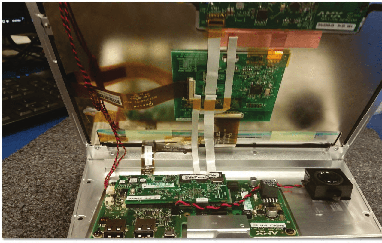
Internal Photos
Modero X S ensor B oard A nd NFC I nterface M odules 20”/19 Table Both Same location 20”/19 Table Both Same location
Operational Description
SAA5968‐03 sensor PCB used on MXT‐1900, MXD‐1900, MXT‐2000 and MXD‐2000 panels This board contain an RFID transceiver chip TRF7970A manufactured by Texas Instruments and is designed to operate at a distance of a few centimeters. The block diagram of the chip, as found in the data sheet by TI, is shown below: List of Antennas to be used on transmitter: The antenna system consists of a PCB loop antenna. The design was provided by Texas Instruments to work with the transceiver chip TRF7970A. See picture below for details: U2 is the TRF7970A transceiver chip. To the right of the chip is a 13.56 MHz crystal oscillator (Y1) driving TRF7970A. The loop antenna occupies the left hand side of the PCB. Since this antenna is neither removable nor replaceable, it complies with FCC 15.203.
Test Report
This report must not be used to claim product certification, approval, or endorsement by NVLAP, NIST, or any agency of the federal government of the United States of America. This Report may only be duplicated in its entirety AMX LLC SAA5968-03 FCC 15.207:2015 FCC 15.225:2015 Report # XNTE0039.8 NVLAP Lab Code: 200881-0 CERTIFICATE OF TEST 2014-12-10 Product compliance is the responsibility of the client; therefore, the tests and equipment modes of operation represented in this report were agreed upon by the client, prior to testing. The results of this test pertain only to the sample(s) tested. The specific description is noted in each of the individual sections of the test report supporting this certificate of test. Last Date of Test: May 08, 2015 AMX LLC Models: SAA5968-03 Radio Equipment Testing Standards Specification Method FCC 15.207:2015 ANSI C63.10:2009 FCC 15.225:2015 ANSI C63.10:2009 Results Method Clause Test Description Applied Results Comments 6.2 Powerline Conducted Emissions Yes Pass 6.4 Field Strength of Fundamental Yes Pass 6.4 Field Strength of Spurious Emissions < 30 MHz Yes Pass 6.5 Field Strength of Spurious Emissions > 30 MHz Yes Pass 6.8 Frequency Stability Yes Pass Deviations From Test Standards None Approved By: Jeremiah Darden, Operations Manager Report No. XNTE0039.82/43 REVISION HISTORY REV 2014.10.14 Revision Number Description Date Page Number 00 None Report No. XNTE0039.83/43 ACCREDITATIONS AND AUTHORIZATIONS REV 2015.2.19 United States FCC - Designated by the FCC as a Telecommunications Certification Body (TCB). Certification chambers, Open Area Test Sites, and conducted measurement facilities are listed with the FCC. A2LA - Accredited by A2LA to ISO / IEC 17065 as a product certifier. This allows Northwest EMC to certify transmitters to FCC and IC specifications. NVLAP - Each laboratory is accredited by NVLAP to ISO 17025 Canada IC - Recognized by Industry Canada as a Certification Body (CB). Certification chambers and Open Area Test Sites are filed with IC. European Union European Commission – Validated by the European Commission as a Conformity Assessment Body (CAB) under the EMC directive and as a Notified Body under the R&TTE Directive. Australia/New Zealand ACMA - Recognized by ACMA as a CAB for the acceptance of test data. Korea MSIP / RRA - Recognized by KCC’s RRA as a CAB for the acceptance of test data. Japan VCCI - Associate Member of the VCCI. Conducted and radiated measurement facilities are registered. Taiwan BSMI – Recognized by BSMI as a CAB for the acceptance of test data. NCC - Recognized by NCC as a CAB for the acceptance of test data. Singapore IDA – Recognized by IDA as a CAB for the acceptance of test data. Israel MOC – Recognized by MOC as a CAB for the acceptance of test data. Hong Kong OFCA – Recognized by OFCA as a CAB for the acceptance of test data. Vietnam MIC – Recognized by MIC as a CAB for the acceptance of test data. SCOPE For details on the Scopes of our Accreditations, please visit: http://www.nwemc.com/accreditations/ http://gsi.nist.gov/global/docs/cabs/designations.html Report No. XNTE0039.84/43 MEASUREMENT UNCERTAINTY TMU.2014.12.03 Measurement Uncertainty When a measurement is made, the result will be different from the true or theoretically correct value. The difference is the result of tolerances in the measurement system that cannot be completely eliminated. To the extent that technology allows us, it has been our aim to minimize this error. Measurement uncertainty is a statistical expression of measurement error qualified by a probability distribution. A measurement uncertainty estimation has been performed for each test per our internal quality document WP 342. The estimation is used to compare the measured result with its "true" or theoretically correct value. The expanded measurement uncertainty (K=2) for each test is on each data sheet. Our measurement data meets or exceeds the measurement uncertainty requirements of the applicable specification; therefore, the test data can be compared directly to the specification limit to determine compliance. The calculations for estimating measurement uncertainty are based upon ETSI TR 100 028 (or CISPR 16-4-2 as applicable), and are available upon request. The following table represents the Measurement Uncertainty (MU) budgets for each of the tests that may be contained in this report. Test + MU - MU Frequency Accuracy (Hz) 0.0007% -0.0007% Amplitude Accuracy (dB) 1.2 dB -1.2 dB Conducted Power (dB) 0.3 dB -0.3 dB Radiated Power via Substitution (dB) 0.7 dB -0.7 dB Temperature (degrees C) 0.7°C -0.7°C Humidity (% RH) 2.5% RH -2.5% RH Voltage (AC) 1.0% -1.0% Voltage (DC) 0.7% -0.7% Field Strength (dB) 4.7 dB -4.7 dB AC Powerline Conducted Emissions (dB) 2.9 dB -2.9 dB Report No. XNTE0039.85/43 FACILITIES REV 2015.2.19 California Labs OC01-13 41 Tesla Irvine, CA 92618 (949) 861-8918 Minnesota Labs MN01-08, MN10 9349 W Broadway Ave. Brooklyn Park, MN 55445 (612)-638-5136 New York Labs NY01-04 4939 Jordan Rd. Elbridge, NY 13060 (315) 554-8214 Oregon Labs EV01-12 22975 NW Evergreen Pkwy Hillsboro, OR 97124 (503) 844-4066 Texas Labs TX01-09 3801 E Plano Pkwy Plano, TX 75074 (469) 304-5255 Washington Labs NC01-05 19201 120 th Ave NE Bothell, WA 9801 (425)984-6600 NVLAP NVLAP Lab Code: 200676-0 NVLAP Lab Code: 200881-0 NVLAP Lab Code: 200761-0 NVLAP Lab Code: 200630-0 NVLAP Lab Code:201049-0 NVLAP Lab Code: 200629-0 Industry Canada 2834B-1, 2834B-3 2834E-1 N/A 2834D-1, 2834D-2 2834G-1 2834F-1 BSMI SL2-IN-E-1154R SL2-IN-E-1152R N/A SL2-IN-E-1017 SL2-IN-E-1158R SL2-IN-E-1153R VCCI A-0029 A-0109 N/A A-0108 A-0201 A-0110 Recognized Phase I CAB for ACMA, BSMI, IDA, KCC/RRA, MIC, MOC, NCC, OFCA US0158 US0175 N/A US0017 US0191 US0157 Report No. XNTE0039.86/43 PRODUCT DESCRIPTION 2014-12-10 Client and Equipment Under Test (EUT) Information Company Name: AMX LLC Address: 3000 Research Drive City, State, Zip: Richardson, TX 75082 Test Requested By: Heath Sharp Model: SAA5968-03 First Da…
Text truncated - open the document above for the full version.
Test Setup Photos
POWERLINE CONDUCTED EMISSIONS WTD.2015.03.10 PSA-ESCI 2015.03.03, EmiR5 2015.03.19.1 POWERLINE CONDUCTED EMISSIONS WTD.2015.03.10 PSA-ESCI 2015.03.03, EmiR5 2015.03.19.1 POWERLINE CONDUCTED EMISSIONS WTD.2015.03.10 PSA-ESCI 2015.03.03, EmiR5 2015.03.19.1 photo Unit 1, MXD-430 (Horizontal) (1).JPG Unit 1, MXD-430 (Horizontal) (2).JPG FIELD STRENGTH OF THE FUNDAMENTAL PSA-ESCI 2015.03.03 photo Unit 1, MXD-430 (On Side) (1).JPG Unit 2, MXD-1000 (Vertical) (1).JPG FIELD STRENGTH OF SPURIOUS EMISSIONS > 30 MHZ PSA-ESCI 2015.03.03 photo Unit 1, MXD-430 (On Side) (1).JPG Unit 2, MXD-1000 (On Side) (1).JPG FIELD STRENGTH OF SPURIOUS EMISSIONS < 30 MHZ PSA-ESCI 2015.03.03
Contact Information
Applicant
Wilson Zhou(Manager, Compliance)
Test Firm
Northwest EMC, Inc.Greg Kiemel
[email protected]503-844-4066
Technical Specifications
| # | Rule Parts | Frequency Range | Power Output |
|---|---|---|---|
| 1 | 15C | 13.56 MHz - 13.56 MHz | - |
Other Applications from AMX LLC
CWU-SAA596805
Sep 17, 2015SAA5968-05
Equipment Class
DXX - Part 15 Low Power Communication Device Transmitter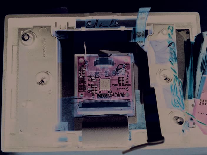
CWU-SAA596807
Sep 17, 2015SAA5968-07
Equipment Class
DXX - Part 15 Low Power Communication Device Transmitter
CWU-HST
Aug 09, 2012Bluetooth Handset
Equipment Class
DSS - Part 15 Spread Spectrum Transmitter
CWU-MVP9I
Jul 26, 2011The MVP-9000i is a touch panel for automation controls
Equipment Class
DTS - Digital Transmission System
CWU-MVP9
Sep 28, 2010WiFi Touch Panel
Equipment Class
NII - Unlicensed National Information Infrastructure TX