DC9IVP-DUDoor Camera Unit
Optex Co Ltd
Click to zoom
Application Details
- Equipment Class
- DSS - Part 15 Spread Spectrum Transmitter
- Date of Grant
- Dec 29, 2013
- Application Purpose
- Original Equipment
- Date of Application
- Dec 29, 2013
- Equipment Note
- Door Camera Unit
- Frequency Range
- 2411.00000000 - 2461.00000000
- Company
- Optex Co Ltd
- Country
- Japan
Documents & Files
Document Text
Text extracted from the exhibit documents filed with the FCC. Open a document above to read the original.
Users Manual
Wireless Video Intercom IVP-DU (Door Camera Unit) Installation Instructions The performance of the system may be affected when mounting the unit in the following environments. - Places that are constantly experiencing vibrations or shocks. - Near a source of hydrosulfuric fumes, phosphorus fumes, ammonia, sulphur, carbon dust and any acidic or noxious materials. - An enclosed space that may cause sounds to echo - Where rain or water may directly hit the unit. Please also note that the video image may be seriously impaired where the camera faces directly into the sun, and also in the following situations. Location where the background is primarily occupied by the sky, such as in the upper floor of an apartment building. Location which has an adjacent white wall that will directly reflect sunlight. Location that receives direct bright sunlight. IVP-DU features Adjustable Camera Angle Battery Operation Capability (for 1 year* 1 ) Auto Day(Color) / Night(IR) Vision Max 2 Units in a System Fluorescent Push Button AC/DC (10~24V) Adaptable Splash Proof for Rain and Outdoor Condition* 2 *1 calculation based on operations for 10sec times 3 activations per a day *2 IPX4 Operating Temparature -20 to 50 degC (-4 F to 122 degF) IMPORTANT NOTICE 1. PARTS IDENTIFICATION 2. constant moisturization Operations under harsh environments such as out of warranted temperature, rapid temperature change, high humidity, constant moisturization may cause the unit to malfunction. Electronic devicesuch as TVs, Radios, PCs, Microwave ovens or any other device with an electric motor may cause the unit to malfunction. Impact or shockscan cause severe damage to the unit. Please handle the unit with care and operate without exerting strong forces. Transmission rangeof communication between units may decrease under the following conditions. - Any unit is installed on a metal surface. - Presence of reinforced concrete, steel doors or other metal construction materials between units. - Places near strong radio sources such as broadcast stations or substations. Location of Installation is critical to optimize image quality captured by the unit. Images will be impaired if the ambient backlight is very strong. Please study the installation environment according to this installation instruction. - The video image is displayed in color during daytime or in well-lit area, but it is displayed in black and white at night or in a dark area. Old and new batteriesmay not be mixed. Do not use lithium batteries for IVP-DU. Leakage or possible explosion can occur. - When Door Camera Unit Low Battery Indicator blinks on HU1, please replace batteries. CHOOSING LOCATION 3. Cable Hole Screws & Anchors Wall Mounting BaseBattery Cover 3-1 Places to Avoid 3-2 Position and Field of View IVP-DU (Door Camera Unit) should be mounted at a position where visitors or potential trespassers can be captured in the camera’s field of view. In a typical setting, IVP-DU is positioned at height between 3.6 -5 feet off the ground. Camera Angle Adjustment Lever can shift the camera’s field of view max +/- 15 degrees to any combination of vertical and horizontal directions. Knock Out Remove the main unit from the mounting base Open a screw cover and loosen the screw Lift the main unit from the mounting base. Fix the mounting base on the wall at the height and location selected. INSTALLATION 4. 4-1 Unit Preparation 4-2 Fixing the Base Push Button Camera Lens Microphone Speaker Door Camera Unit (Front) Camera Angle Adjustment Lever Battery Compartment Pairing Button External Power Input Fixing Screw Door Camera Unit (Back) NOTE: When using an external power source, make a knockout hole on the Mounting Base before fixing to a wall. Place the Mounting Base on a horizontal surface front side down. Point a driver in the center of the knock out and apply gentle impacts to break a hole through. Wall Mounting Base Holes drilled in wall Mounting Screws Insert a driver into a small cavity on a rim to pop up the main unit. ATTENTION: Thank you for purchasing the iVISION+ wireless video intercom. Before installation and usage, please read this instruction manual thoroughly and keep this safe for future reference. Knock Out The Camera Door Unit may also be powered from an external power source. If available, connect the unit directly to the existing AC/DC 10-24V doorbell power supply or, alternatively, an AC/DC 10-24V third party’s external power pack may be used. Pass the bell wire or the wire from a power pack through the mounting plate before fixing the plate to the wall. Connect the wire to the Power input terminal. Power input terminal (1) Fix a Wall Mounting Base to a desired location using four screws and anchors included in a package. (2) On to the secured mounting base, hook upper rim of the main unit and then, press in the entire unit. (3) Tighten a screw at the bottom to secure the unit. NOTE: One Handheld Monitor Unit (IVP-HU) must be configured to have a HOME ID* 1 prior to paring up with other iVISION+ devices. For setting up a new HOME ID, refer to the Installation Instruction of IVP-HU. A Handheld Monitor Unit bundled with Door Camera Unit already has a HOME ID set up and paired up to each other. Proceed to OPERATION CHECK unless additional pairing is required. (1) Enabling Paring Mode of a Door Camera Unit (IVP-DU) Press a PUSH button on the front then push pairing button located at the bottom of battery compartment until the unit makes a beeping sound. The Door Camera Unit will clear its HOME ID assignment and starts looking for a New HOME ID. 5 short beeps will repeat until the unit is paired or power/batteries displacement. (2) Assigning a HOME ID to a Door Camera Unit (IVP-DU) When a Handheld Monitor Unit in a paring mode, choose “SCAN” by pressing Left Function Key. Door Camera Unit will automatically be assigned to a new HOME ID and beeping will stop. Repeat the same procedure for an addition unit. The first paired IVP-DU will be assigned as DU1. The se…
Text truncated - open the document above for the full version.
External Photos
EXHIBIT B - EUT EXTERNAL PHOTOGRAPHS EUT—Top View EUT—Bottom View EUT—Right Side View EUT— Left Side View
ID Label/Location Info
EXHIBIT A - FCC ID LABELING AND LOCATION FCC ID Label Proposed FCC ID Label Location The label shown shall be permanently affixed at a conspicuous location on the device and be readily visible to the user at the time purchase (Labeling requirements per 2.925) Label Here
Internal Photos
EXHIBIT B - EUT EXTERNAL PHOTOGRAPHS EUT- Battery Cover Off View EUT-Uncover View EUT- Main Board Top View EUT- Main Board Bottom View EUT- RF Module View EUT- Antenna View TX&RX antenna EUT- LCD Board Top View EUT- LCD Board Bottom View EUT- Loudspeaker Top View EUT- Loudspeaker Bottom View
Test Report
Note: This test report is prepared for the customer shown above and for the device described herein. It may not be duplicated or used in part without prior written consent from Bay Area Compliance Laboratories Corp. This report must not be used by the customer to claim product certification, approval, or endorsement by NVLAP*, or any agency of the Federal Government. * This report may contain data that are not covered by the NVLAP accreditation and shall be marked with an asterisk “” ★ (Rev.2). This report is valid only with a valid digital signature. The digital signature may be available only under the Adobe software above version 7.0. FCC PART 15.247 TEST REPORT For Optex Co., Ltd. 5-8-12, Ogoto Otsu-Shiga-Ken, Japan FCC ID: DC9IVP-DU Report Type: Original Report Product Type: Door Camera Unit Test Engineer: Allen Qiao Report Number: R2DG1311250 16-00A Report Date: 2013 -12-06 Reviewed By: Ivan Cao EMC Engineer Test Laboratory: Bay Area Compliance Laboratories Corp. (Dongguan) No.69 Pulongcun, Puxinhu Industrial Zone, Tangxia, Dongguan, Guangdong, China Tel: +86-769-86858888 Fax: +86-769-86858891 www.baclcorp.com.cn Bay Area Compliance Laboratories Corp. (Dongguan) Report No.: R2DG131125016-00A FCC Part 15.247 Page 2 of 39 TABLE OF CONTENTS GENERAL INFORMATION ....................................................................................................................................... 4 PRODUCT DESCRIPTION FOR EQUIPMENT UNDER TEST (EUT) ..................................................................................... 4 OBJECTIVE ................................................................................................................................................................... 4 RELATED SUBMITTAL(S)/GRANT(S) ............................................................................................................................. 4 TEST METHODOLOGY .................................................................................................................................................. 4 TEST FACILITY ............................................................................................................................................................. 4 SYSTEM TEST CONFIGURATION .......................................................................................................................... 6 DESCRIPTION OF TEST CONFIGURATION ...................................................................................................................... 6 EUT EXERCISE SOFTWARE .......................................................................................................................................... 6 EQUIPMENT MODIFICATIONS ....................................................................................................................................... 6 SUPPORT EQUIPMENT LIST AND DETAILS .................................................................................................................... 6 EXTERNAL CABLE ........................................................................................................................................................ 6 BLOCK DIAGRAM OF TEST SETUP ................................................................................................................................ 7 SUMMARY OF TEST RESULTS ............................................................................................................................... 8 FCC §15.247 (i) & §1.1310 & §2.1091- MAXIMUM PERMISSIBLE EXPOSURE (MPE) ......................................... 9 APPLICABLE STANDARD .............................................................................................................................................. 9 FCC §15.203 - ANTENNA REQUIREMENT ........................................................................................................... 10 APPLICABLE STANDARD ............................................................................................................................................ 10 ANTENNA CONNECTOR CONSTRUCTION .................................................................................................................... 10 FCC §15.207 (a) – AC LINE CONDUCTED EMISSIONS ..................................................................................... 11 APPLICABLE STANDARD ............................................................................................................................................ 11 MEASUREMENT UNCERTAINTY .................................................................................................................................. 11 EUT SETUP ................................................................................................................................................................ 11 EMI TEST RECEIVER SETUP ....................................................................................................................................... 12 TEST PROCEDURE ...................................................................................................................................................... 12 CORRECTED AMPLITUDE & MARGIN CALCULATION ................................................................................................. 12 TEST EQUIPMENT LIST AND DETAILS ......................................................................................................................... 13 TEST RESULTS SUMMARY .......................................................................................................................................... 13 TEST DATA ................................................................................................................................................................ 13 FCC §15.209, §15.205 & §15.247(d) - SPURIOUS EMISSIONS ............................................................................. 16 APPLICABLE STANDARD .…
Text truncated - open the document above for the full version.
Test Setup Photos
EXHIBIT D - TEST SETUP PHOTOGRAPHS Conducted Emissions - Front View Conducted Emissions – Side View Radiated Emissions Below 1GHz - Front View Radiated Emissions Below 1GHz –Rear View Radiated Emissions Above 1GHz - Front View Radiated Emissions Above 1GHz –Rear View
Contact Information
Applicant
Hiroaki Nakamura(Manager, System Development Sec.)
Test Firm
Bay Area Compliance Laboratories Corp. (Dongguan)John Chan
[email protected]86-769-86858888
Technical Specifications
| # | Rule Parts | Frequency Range | Power Output |
|---|---|---|---|
| 1 | 15C | 2.41 GHz - 2.46 GHz | 17.66 mW |
Other Applications from Optex Co Ltd
DC9IVP-GU
Aug 22, 2014Wireless Gateway
Equipment Class
DSS - Part 15 Spread Spectrum Transmitter
DC9-IVS166
Feb 26, 2014K-Band VCO Transceiver
Equipment Class
FDS - Part 15 Field Disturbance Sensor
DC9-VDS005
Feb 04, 2014Vehicle detection sensor
Equipment Class
DXX - Part 15 Low Power Communication Device Transmitter
DC9IVP-HU
Dec 29, 2013Handheld Monitor Unit
Equipment Class
DSS - Part 15 Spread Spectrum Transmitter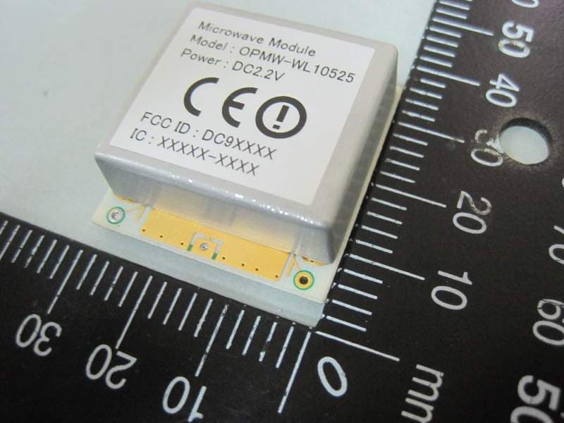
DC9OPMWWL
Feb 28, 2012Microwave Module
Equipment Class
FDS - Part 15 Field Disturbance Sensor