DC9IVP-GUWireless Gateway
Optex Co Ltd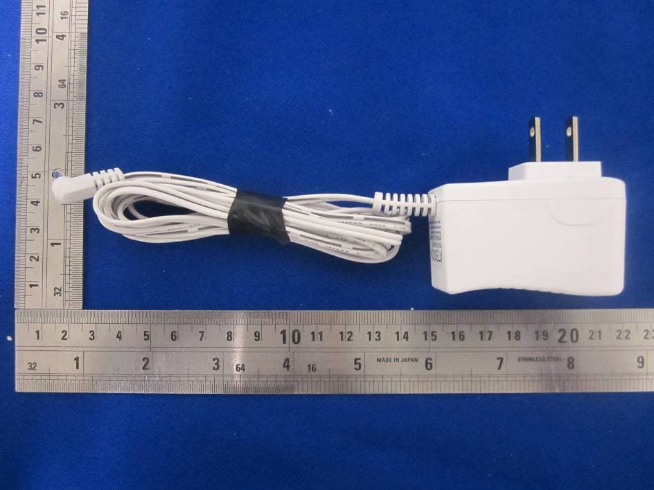
Click to zoom
Application Details
- Equipment Class
- DSS - Part 15 Spread Spectrum Transmitter
- Date of Grant
- Aug 22, 2014
- Application Purpose
- Original Equipment
- Date of Application
- Aug 22, 2014
- Equipment Note
- Wireless Gateway
- Frequency Range
- 2411.00000000 - 2461.00000000
- Company
- Optex Co Ltd
- Country
- Japan
Documents & Files
Document Text
Text extracted from the exhibit documents filed with the FCC. Open a document above to read the original.
Users Manual
INDEX - 1 -- 1 - iVISION+ User Manual 1-1. Basic features of iVISION+ 1-2. Expanding iVISION+ with an optional unit 2-1. Handheld Monitor Unit (IVP-HU) 2-2. Door Camera Unit (IVP-DU) 2-3. Gateway Chime Unit (IVP-GU) 3-2. How to turn ON/OFF 3-1. Getting ready with iVISION+ system 3-3. Date and Time Setting 3-5. Changing Brightness on Handheld Monitor Unit 3-4. Changing Volumes 4-1. Answering to a Door Camera Unit 4-2. Using SNAP function to capture an image 4-4. Ending ANSWER / BROWSING MODE (Returning to IDLE MODE) 4-3. Operating OPEN DOOR function 5-1. How “Auto Recording” works 5-2. Changing number of images to be captured in “Auto Recording” 5-3. Note about timings for capturing images 6-1. Viewing Images 6-3. Viewing Images from Your PC 6-2. Deleting Stored Images 7-1. Talk Switching Mode Setting 1. What you can do with iVISION+ 2. Overview of iVISION+ devices 3. Before Using iVISION+ 4. How to Use Basic Features 5. Auto Recording Images 6. Handling Stored Images 7. Other Settings 9. Trouble Shooting 8. Frequently Asked Questions - 14 - - 2 - 1. What you can do with iVISION+ 1-1. Basic features of iVISION+ 1-2. Expanding iVISION+ with an optional unit iVISION+ is a wireless video intercom system with multi unit expansion capability. When someone comes to your door and presses the button on the Door Camera Unit (Max. 2 units), the Handheld Monitor Unit (Max. 4 units) rings a chime and displays a video image from the camera. The Handheld Monitor Unit will store still images if no one was there to answer the call. Knowing who is/was at your door Replace an old door bell with video If you already have a door bell with 10-24VAC/DC power supplied, enable Door Camera Unit for a browsing feature and actively view from a Handheld Monitor Unit anytime you like. Gateway Chime Unit adds a extra chime to let you know someone is at the door. Operate third party equipment (e.g. Door Lock) Connecting the OPTEX RC-20U to the iVISION+ enables “Open Door” function to operate third party equipment connected to the output relay on RC-20U. - 13 - Subjects show up in black and white or background is a greenish color Is the background dark, such as at night time? • Subjects shows up as black and white due to color-dulling when it becomes dark. Also could appear “greenish” in areas covered by outdoor lights. This is normal at night when lighting is provided by the IR LED in the Door Camera Unit. The visitors face is dark or unclear in the video image. If the Door Camera Unit is mounted in an area with a bright backlight (either from sunlight or outdoor lighting) the visitor’s face may appear as a silhouette. • Check that the camera lens is not dirty or has condensation on the surface. Wipe with a dry cloth. • Adjust the brightness setting (Refer to Sec. 3-5) • Re-locate the camera to a position with no backlight. The video image shows up whitish or white lines or rings show up in images. There are small black spots in the background of the image. The video image flickers. The video image is distorted. The voice is cut off while answering/browsing a Door Camera Unit. It may be difficult to see the image if the camera lens receives strong light such as sunlight. • Avoid direct sunlight by re-positioning or placing a shade. • Adjust the brightness setting (Refer to Sec. 3-5) Does the sun show up in the image? The center of the sun can appears as black spots if the sun is in a view. • Avoid direct sunlight by re-positioning or placing a shade. • Adjust the brightness setting (Refer to Sec. 3-5) Is a microwave oven or a wireless LAN device in operation near to the Handheld Monitor Unit? • Re-locate the Handheld Monitor Unit away from such equipment. Fluorescent lights nearby to the Camera Door Unit can cause the image to flicker. Symptoms Probable causes & solutions 9. Trouble Shooting - 12 - Symptoms A howling noise distorts the sound. The ring tone cannot be heard. The charging does not start when the Handheld Monitor Unit is placed in the charging cradle. Probable causes & solutions • Check battery status on Handheld Monitor Unit and charge if necessary. Change volume setting on the Handheld Monitor Unit. (Refer to Sec. 3-1 “Check 3”) 8. Frequently Asked Questions. Q: Is the iVISION+ compatible to the old iVISION A: No, but the iVISION+ is compatible with OPTEX RC-20U, which allows the iVISION+ additional feature to operate a third-party equipment. Q: If I connect existing door bell wires to the Door Camera Unit, will the bell still ring? A: No. The input terminals on the Door Camera Unit are strictly for power purposes. Please use Gateway Chime Unit to replace the existing doorbell for additional sound. Q: Can I unload the images from the Handheld Monitor Unit to my PC? A: Yes. micro-USB cable is required to unload images. (Refer to Sec. 6-3) Q. What is the RF transmission range for iVISION+? A: Signal reaches a maximum of six hundred ft (clear line of site). RF signal condition may vary depending on surrounding environment and materials. Q: How many Handheld Monitor Units can I have communicating to a Door Camera Unit? A: One at a time. If another Door Camera Unit makes a call while answering, the call will be withheld until the current session ends. A: There is no volume adjustment for the Door Camera Unit. Q: How can I adjust the volume on the Door Camera Unit? If the Handheld Monitor Unit is too close to the Door Camera unit, a howling sound can occur. • Keep the Handheld Monitor Unit away from the Door Camera unit. Is the AC adaptor disconnected from the socket or the charging cradle? • Please check all power connections. • Clean the charging terminals with a dry cloth. The display on a Handheld Monitor Unit is black and does not respond to any key. Is the unit in standby? • Press any button to energize the display. • Make sure the unit is powered on. (Refer to Sec. 3-2) • If the battery has ran out, charge the Handheld Monitor Unit for about 10 minutes before turning ON. - 3 - 2. Overview of iVISION+ de…
Text truncated - open the document above for the full version.
External Photos
EXHIBIT B - EUT EXTERNAL PHOTOGRAPHS EUT– Top View EUT– Bottom View EUT– Side View EUT– Side View EUT– Side View EUT – Side View EUT – Port View EUT – Adapter View EUT – Adapter Label View
ID Label/Location Info
EXHIBIT A - FCC ID LABELING AND LOCATION FCC ID Label Proposed FCC ID Label Location The label shown shall be permanently affixed at a conspicuous location on the device and be readily visible to the user at the time purchase (Labeling requirements per 2.925) Label Here
Internal Photos
EXHIBIT C - EUT INTERNAL PHOTOGRAPHS EUT – Uncover View EUT – Cover Off View EUT – Main Board Top View EUT – Main Board Bottom View EUT – RF Chip View EUT – Antenna View EUT – Speaker View
RF Exposure Info
Bay Area Compliance Laboratories Corp. (Dongguan) Report No.: RDG140721003-00 FCC Part 15.247 Page 8 of 38 FCC §15.247 (i) & §1.1307 (b) (1) & §2.1091- MAXIMUM PERMISSIBLE EXPOSURE (MPE) Applicable Standard According to subpart 15.247(i)and subpart §1.1307(b)(1), systems operating under the provisions of this section shall be operated in a manner that ensures that the public is not exposed to radio frequency energy level in excess of the Commission’s guidelines. Limits for Maximum Permissible Exposure (MPE) (§1.1310, §2.1091) (B) Limits for General Population/Uncontrolled Exposure Frequency Range (MHz) Electric Field Strength (V/m) Magnetic Field Strength (A/m) Power Density (mW/cm 2 ) Averaging Time (minutes) 0.3–1.34 614 1.63 *(100) 30 1.34–30 824/f 2.19/f *(180/f²) 30 30–300 27.5 0.073 0.2 30 300–1500 / / f/1500 30 1500–100,000 / / 1.0 30 f = frequency in MHz; * = Plane-wave equivalent power density; According to §1.1310 and §2.1091 RF exposure is calculated. Calculated Formulary: Predication of MPE limit at a given distance S = PG/4πR² = power density (in appropriate units, e.g. mW/cm 2 ); P = power input to the antenna (in appropriate units, e.g., mW); G = power gain of the antenna in the direction of interest relative to an isotropic radiator, the power gain factor, is normally numeric gain; R = distance to the center of radiation of the antenna (appropriate units, e.g., cm); Calculated Data: Frequency (MHz) Antenna Gain Conducted Power Evaluation Distance (cm) Power Density (mW/cm 2 ) MPE Limit (mW/cm 2 ) (dBi) (numeric) (dBm)(mW) 2461 0 1.0 10.8612.1920 0.0024 1.0 Result: The device meet FCC MPE at 20cm distance.
Test Report
Note: This test report is prepared for the customer shown above and for the device described herein. It may not be duplicated or used in part without prior written consent from Bay Area Compliance Laboratories Corp. (Dongguan). This report is valid only with a valid digital signature. The digital signature may be available only under the Adobe software above version 7.0. FCC PART 15.247 TEST REPORT For OPTEX CO., LTD. 5-8-12, Ogoto Otsu, Shiga, Japan FCC ID: DC9IVP-GU Report Type: Original Report Product Type: Wireless Gateway Test En gineer: Dean Liu Re port Number: RDG140721003-00 Re port Date: 2014-08-12 Reviewed B y: Sula Huang RF En gineer Test Laboratory: Bay Area Compliance Laboratories Corp. (Dongguan) No.69 Pulongcun, Puxinhu Industrial Zone, Tangxia, Dongguan, Guangdong, China Tel: +86-769-86858888 Fax: +86-769-86858891 www.baclcorp.com.cn Bay Area Compliance Laboratories Corp. (Dongguan) Report No.: RDG140721003-00 FCC Part 15.247 Page 2 of 38 TABLE OF CONTENTS GENERAL INFORMATION ....................................................................................................................................... 4 PRODUCT DESCRIPTION FOR EQUIPMENT UNDER TEST (EUT) ..................................................................................... 4 OBJECTIVE ................................................................................................................................................................... 4 RELATED SUBMITTAL(S)/GRANT(S) ............................................................................................................................. 4 TEST METHODOLOGY .................................................................................................................................................. 4 TEST FACILITY ............................................................................................................................................................. 4 SYSTEM TEST CONFIGURATION .......................................................................................................................... 5 DESCRIPTION OF TEST CONFIGURATION ...................................................................................................................... 5 EUT EXERCISE SOFTWARE .......................................................................................................................................... 5 EQUIPMENT MODIFICATIONS ....................................................................................................................................... 5 SUPPORT EQUIPMENT LIST AND DETAILS .................................................................................................................... 5 EXTERNAL CABLE ........................................................................................................................................................ 5 BLOCK DIAGRAM OF TEST SETUP ................................................................................................................................ 6 SUMMARY OF TEST RESULTS ............................................................................................................................... 7 FCC §15.247 (i) & §1.1307 (b) (1) & §2.1091- MAXIMUM PERMISSIBLE EXPOSURE (MPE) .............................. 8 APPLICABLE STANDARD .............................................................................................................................................. 8 FCC §15.203 - ANTENNA REQUIREMENT ............................................................................................................. 9 APPLICABLE STANDARD .............................................................................................................................................. 9 ANTENNA CONNECTOR CONSTRUCTION ...................................................................................................................... 9 FCC §15.207 (a) – AC LINE CONDUCTED EMISSIONS ..................................................................................... 10 APPLICABLE STANDARD ............................................................................................................................................ 10 MEASUREMENT UNCERTAINTY .................................................................................................................................. 10 EUT SETUP ................................................................................................................................................................ 10 EMI TEST RECEIVER SETUP ....................................................................................................................................... 11 TEST PROCEDURE ...................................................................................................................................................... 11 CORRECTED AMPLITUDE & MARGIN CALCULATION ................................................................................................. 11 TEST EQUIPMENT LIST AND DETAILS ......................................................................................................................... 12 TEST RESULTS SUMMARY .......................................................................................................................................... 12 TEST DATA ................................................................................................................................................................ 12 FCC §15.209, §15.205 & §15.247(d) - SPURIOUS EMISSIONS ............................................................................. 17 APPLICABLE STANDARD ............................................................................................................................................ 17 MEASUREMENT UNCERTAINTY ..............................................................................................................…
Text truncated - open the document above for the full version.
Test Setup Photos
EXHIBIT D - TEST SETUP PHOTOGRAPHS Conducted Emission--Front View (AC 12V) Conducted Emission – Side View (AC 12V) Conducted Emission--Front View (DC 12V) Conducted Emission – Side View (DC 12V) Radiated Emission –Front View (Below 1GHz) (AC 12V) Radiated Emission –Rear View (Below 1GHz) (AC 12V) Radiated Emission –Front View (Below 1GHz) (DC 12V) Radiated Emission –Rear View (Below 1GHz) (DC 12V) Radiated Emission- Front View (Above 1GHz) (AC 12V) Radiated Emission- Rear View (Above 1GHz) (AC 12V) Radiated Emission- Front View (Above 1GHz) (DC 12V) Radiated Emission- Rear View (Above 1GHz) (DC 12V)
Contact Information
Applicant
Hiroaki Nakamura(Manager, System Development Sec.)
Test Firm
Bay Area Compliance Laboratories Corp. (Dongguan)John Chan
[email protected]86-769-86858888
Technical Specifications
| # | Rule Parts | Frequency Range | Power Output |
|---|---|---|---|
| 1 | 15C | 2.41 GHz - 2.46 GHz | 12.00 mW |
Other Applications from Optex Co Ltd

DC9-IVS166
Feb 26, 2014K-Band VCO Transceiver
Equipment Class
FDS - Part 15 Field Disturbance Sensor
DC9-VDS005
Feb 04, 2014Vehicle detection sensor
Equipment Class
DXX - Part 15 Low Power Communication Device Transmitter
DC9IVP-DU
Dec 29, 2013Door Camera Unit
Equipment Class
DSS - Part 15 Spread Spectrum Transmitter
DC9IVP-HU
Dec 29, 2013Handheld Monitor Unit
Equipment Class
DSS - Part 15 Spread Spectrum Transmitter
DC9OPMWWL
Feb 28, 2012Microwave Module
Equipment Class
FDS - Part 15 Field Disturbance Sensor