DC9OPMWMicrowave Module
Optex Co Ltd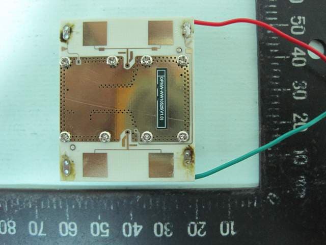
Click to zoom
Application Details
- Equipment Class
- FDS - Part 15 Field Disturbance Sensor
- Date of Grant
- May 20, 2010
- Application Purpose
- Original Equipment
- Date of Application
- May 20, 2010
- Equipment Note
- Microwave Module
- Frequency Range
- 10525.00000000 - 10525.00000000
- Company
- Optex Co Ltd
- Country
- Japan
Documents & Files
Document Text
Text extracted from the exhibit documents filed with the FCC. Open a document above to read the original.
Users Manual
Operation Manual 1. Scope 2. Note and Warning 3. Electrical Specification 4. Pin Assignment 5. FCC Statement & IC Statement 1. Scope This module is designed for motion sensing applications. It consists of Oscillator, Mixer, Filter, detecter and 2element Antennas(T), 2element Antennas(R). In addition, It have Frequency adjustment, Maintenance structure and Shield case. 2. Note and Warning The product is wireless device.It can radiation and receive RF signal. These electric equipments are very sensitive for RF signal in airplane,hospital,and place to life relate. The electric equipments almost interference from RF signal if it not shelter enough and flaw in design. In order to avoid damage for life and property,in compliance with standard of ever place and electric equipment to use the product. If the product collide,operate improper,and maintain by oneself. We are not indemnification. Place responsibility by oneself. The product need solder a By Pass Capacitor in 22~100nF on DC +5V supply point of the main PCB. The value of By Pass Capacitor is for reference. Determination of value must according to require of your system. 3. Electrical Specification Operating Voltage 5.00.2 V dc Operating Current 35mA typ. (CW operation) Center Frequency 10.525GHz typ. Frequency Stability 5 MHz max. (-30 to +65) Output Power 20mw (E.I.R.P.) max. Second Harmonic Emission 1W max. Antenna beamwidth (-3dB) E-Plane H-Plane 70 deg. nom. 40 deg. nom. 4. Pin Assignment 1. +5V 2. GND 3. IF out 5. FCC Statement & IC Statement FCC Statement Federal Communication Commission Interference Statement This equipment has been tested and found to comply with the limits for a Class B digital device,pursuant to Part 15 of the FCC Rules. These limits are designed to provide reasonable protection against harmful interference in a residential installation. This equipment generates, uses and can radiate radio frequency energy and, if not installed and used in accordance with the instructions, may cause harmful interference to radio communications. However, there is no guarantee that interference will not occur in a particular installation. If this equipment does cause harmful interference to radio or television reception, which can be determined by turning the equipment off and on, the user is encouraged to try to correct the interference by one of the following measures: Reorient or relocate the receiving antenna. Increase the separation between the equipment and receiver. Connect the equipment into an outlet on a circuit different from that to which the receiver is connected. Consult the dealer or an experienced radio/TV technician for help. FCC Caution: Any changes or modifications not expressly approved by the party responsible for compliance could void the user’s authority to operate this equipment. This device complies with Part 15 of the FCC Rules. Operation is subject to the following two conditions: (1) This device may not cause harmful interference, and (2) this device must accept any interference received, including interference that may cause undesired operation. For product available in the USA/Canada market, only channel 1~11 can be operated. Selection of other channels is not possible. This device and its antenna(s) must not be co-located or operation in conjunction with any other antenna or transmitter. IMPORTANT NOTE: FCC Radiation Exposure Statement: This equipment complies with FCC radiation exposure limits set forth for an uncontrolled environment. This equipment should be installed and operated with minimum distance 20cm between the radiator & your body. IMPORTANT NOTE: This module is intended for OEM integrator. The OEM integrator is still responsible for the FCC compliance requirement of the end product, which integrates this module. 20cm minimum distance has to be able to be maintained between the antenna and the users for the host this module is integrated into. Under such configuration, the FCC radiation exposure limits set forth for an population/uncontrolled environment can be satisfied. Any changes or modifications not expressly approved by the manufacturer could void the user's authority to operate this equipment. USERS MANUAL OF THE END PRODUCT: In the users manual of the end product, the end user has to be informed to keep at least 20cm separation with the antenna while this end product is installed and operated. The end user has to be informed that the FCC radio-frequency exposure guidelines for an uncontrolled environment can be satisfied. The end user has to also be informed that any changes or modifications not expressly approved by the manufacturer could void the user's authority to operate this equipment. If the size of the end product is smaller than 8x10cm, then additional FCC part 15.19 statement is required to be available in the users manual: This device complies with Part 15 of FCC rules. Operation is subject to the following two conditions: (1) this device may not cause harmful interference and (2) this device must accept any interference received, including interference that may cause undesired operation. LABEL OF THE END PRODUCT: The final end product must be labeled in a visible area with the following " Contains TX FCC ID:DC9OPMW ". If the size of the end product is larger than 8x10cm, then the following FCC part 15.19 statement has to also be available on the label: This device complies with Part 15 of FCC rules. Operation is subject to the following two conditions: (1) this device may not cause harmful interference and (2) this device must accept any interference received, including interference that may cause undesired operation. IC Statement This Class B digital apparatus complies with Canadian ICES-003. Operation is subject to the following two conditions: (1) this device may not cause interference, and (2) this device must accept any interference, including interference that may cause undesired operation of the device. Cet appareil numérique de la classe B est conforme á la …
Text truncated - open the document above for the full version.
External Photos
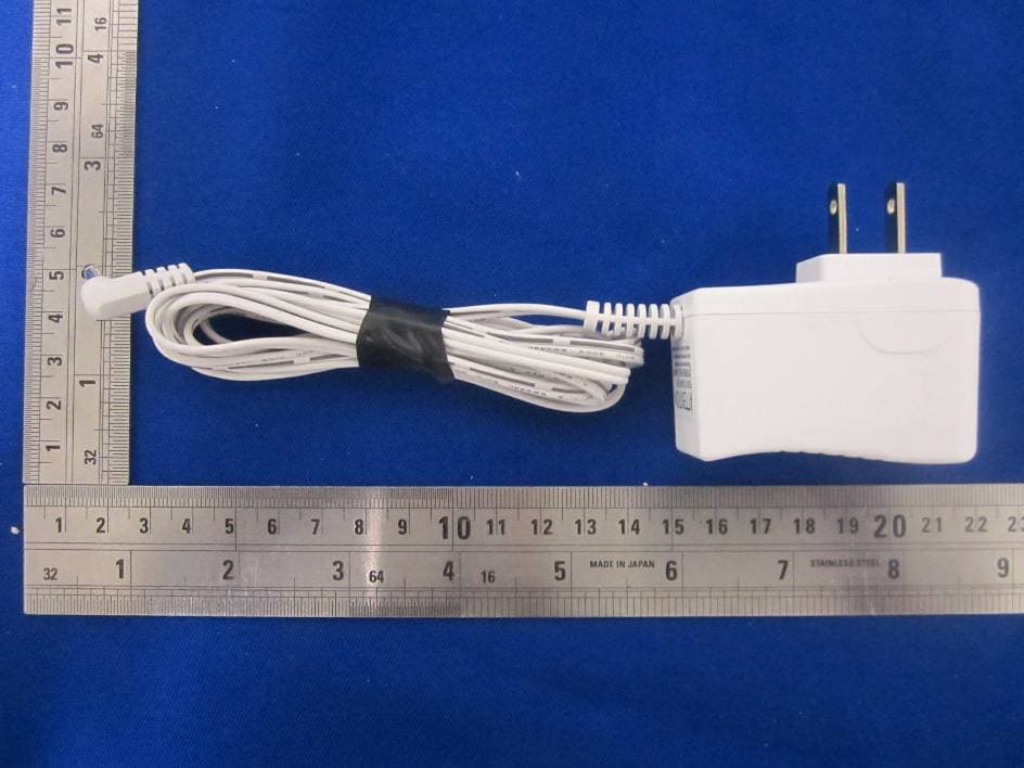
SPORTON International Inc. PAGE NUMBER : A1 OF A1 TEL : 886-2-2696-2468 ISSUED DATE : May 05, 2010 FAX : 886-2-2696-2255 APPENDIX A. Photographs of EUT
ID Label/Location Info
17mm 17mm17mm 17mm 34mm 34mm34mm 34mm
Internal Photos
SPORTON International Inc. PAGE NUMBER : A1 OF A1 TEL : 886-2-2696-2468 ISSUED DATE : May 05, 2010 FAX : 886-2-2696-2255 APPENDIX A. Photographs of EUT
Test Report
FCC Test Report Report No. : FR041334 SPORTON INTERNATIONAL INC. Page No. : 2 of 41 TEL : 886-2-2696-2468 Report Version : Rev. 01 FAX : 886-2-2696-2255 FCC ID DC9OPMW TABLE OF CONTENTS 1 GENERAL DESCRIPTION .................................................................................................................... 5 1.1 Information.............................................................................................................................................. 5 1.2 Additional Information Provided by the Submitter .................................................................................. 8 1.3 Ancillary and/or Support Equipment ....................................................................................................... 9 1.4 EUT Setups ............................................................................................................................................ 9 1.5 Testing Applied Standards ................................................................................................................... 12 1.6 Testing Location ................................................................................................................................... 12 1.7 Abbreviations Used for the Test Report ............................................................................................... 12 2 TEST CONFIGURATION OF EQUIPMENT UNDER TEST ................................................................ 13 2.1 Test Channel Frequencies ................................................................................................................... 13 2.2 Conformance Tests and Related Test Frequencies ............................................................................ 13 3 TRANSMITTER TEST RESULT .......................................................................................................... 14 3.1 AC Power Conducted Emissions ......................................................................................................... 14 3.2 Occupied Bandwidth ............................................................................................................................ 18 3.3 Field Strength of Fundamental ............................................................................................................. 21 3.4 Transmitter Spurious Emissions........................................................................................................... 26 3.5 Antenna Requirements ......................................................................................................................... 37 3.6 Maximum Permissible Exposure .......................................................................................................... 38 4 LIST OF MEASURING EQUIPMENTS ................................................................................................ 40 5 CERTIFICATION OF TAF ACCREDITATION ..................................................................................... 41 APPENDIX A. PHOTOGRAPHS OF EUT........................................................................................2 APPENDIX B. TEST PHOTOS.....................................................................................................9 FCC Test Report Report No. : FR041334 SPORTON INTERNATIONAL INC. Page No. : 3 of 41 TEL : 886-2-2696-2468 Report Version : Rev. 01 FAX : 886-2-2696-2255 FCC ID DC9OPMW SUMMARY OF TEST RESULT FCC Standard Requirements and Conformance Test Specifications Report Clause Ref. Std. Clause Description Result Remark 3.1 15.207 AC Power Conducted Emissions Complied - 3.2 15.215(c) Occupied Bandwidth Complied - 3.3 15.245(b) Field Strength of Fundamental Complied - 3.4 15.245(b) Transmitter Spurious Emissions Complied - 3.5 15.203 Antenna Requirements Complied - 3.6 2.1091 Maximum Permissible Exposure Complied - FCC Test Report Report No. : FR041334 SPORTON INTERNATIONAL INC. Page No. : 4 of 41 TEL : 886-2-2696-2468 Report Version : Rev. 01 FAX : 886-2-2696-2255 FCC ID DC9OPMW Certificate No. : CB9905011 REVISION HISTORY REPORT NO. VERSION DESCRIPTION ISSUED DATE FR041334 Rev. 01 Initial issue of report May 05, 2010 FCC Test Report Report No. : FR041334 SPORTON INTERNATIONAL INC. Page No. : 5 of 41 TEL : 886-2-2696-2468 Report Version : Rev. 01 FAX : 886-2-2696-2255 FCC ID DC9OPMW 1 General Description 1.1 Information 1.1.1 Operating Frequency Range(s) Operating Frequency Range(s) Range 1: 902 – 928 MHz Range 2: 2435 – 2465 MHz Range 3: 5785 – 5815 MHz Range 4: 10.5 – 10.55 GHz Range 5: 24.075 – 24.175 GHz 1.1.2 The Channel Plan(s) The Channel Plan(s) Channel Plan 1: 10.5 – 10.55 GHz Band Nominal Channel Bandwidth 1: 5 MHz, 10.525 GHz Channel Plan 2: N/A Nominal Channel Bandwidth 2: N/A 1.1.3 Transmit Operating Modes The Different Transmit Operating Modes Operating mode 1: Single Antenna Equipment Operating mode 2: Smart Antenna Systems - without beam forming Operating mode 3: Smart Antenna Systems - with beam forming 1.1.4 Smart Antenna Systems In Case of Smart Antenna Systems Smart Antenna Systems: N/A The number of Receive chains: N/A The number of Transmit chains: N/A Equal power distribution among the transmit chains:Ye s No In case of beam forming, the maximum beam forming gain: - dB FCC Test Report Report No. : FR041334 SPORTON INTERNATIONAL INC. Page No. : 6 of 41 TEL : 886-2-2696-2468 Report Version : Rev. 01 FAX : 886-2-2696-2255 FCC ID DC9OPMW 1.1.5 Antenna Information Antenna Information Equipment placed on the market without antennas Integral antenna (Antenna permanently attached) Integral antenna gain: 7.36 dBi Temporary RF connector provided No temporary RF connector provided External antenna (dedicated antennas) Single power level with corresponding antenna(s) Multiple power settings and corresponding antenna(s) Professional Install Unique antenna connector BIOS lock. NOTE: EUT antenna complied with FCC 15.203, antenna requirements. 1.1.6 Type of Equipment Type …
Text truncated - open the document above for the full version.
Test Setup Photos
Report No.: FR041334 FCC ID: DC9OPMW Page No. : 1 of 9 Appendix B. Test Photos Report No.: FR041334 FCC ID: DC9OPMW Page No. : 2 of 9 1. Photographs of Conducted Emissions Test Configuration FRONT VIEW REAR VIEW Report No.: FR041334 FCC ID: DC9OPMW Page No. : 3 of 9 2. Photographs of Radiated Emissions Test Configuration Test Configuration: 9kHz ~30MHz FRONT VIEW REAR VIEW Report No.: FR041334 FCC ID: DC9OPMW Page No. : 4 of 9 Test Configuration: 30MHz~1GHz FRONT VIEW REAR VIEW Report No.: FR041334 FCC ID: DC9OPMW Page No. : 5 of 9 SIDE VIEW Report No.: FR041334 FCC ID: DC9OPMW Page No. : 6 of 9 Test Configuration: 18GHz~26.5GHz FRONT VIEW REAR VIEW Report No.: FR041334 FCC ID: DC9OPMW Page No. : 7 of 9 Test Configuration: 26.5GHz~40GHz FRONT VIEW REAR VIEW Report No.: FR041334 FCC ID: DC9OPMW Page No. : 8 of 9 Test Configuration: 40GHz~60GHz FRONT VIEW REAR VIEW Report No.: FR041334 FCC ID: DC9OPMW Page No. : 9 of 9 Test Configuration: 10.525GHz FRONT VIEW REAR VIEW
Contact Information
Applicant
Hiroaki Nakamura(Manager, System Development Sec.)
Test Firm
Sporton International Inc.Alex Chen
Technical Specifications
| # | Rule Parts | Frequency Range | Power Output |
|---|---|---|---|
| 1 | 15.245 | 10.53 GHz - 10.53 GHz | - |
Other Applications from Optex Co Ltd
DC9IVP-GU
Aug 22, 2014Wireless Gateway
Equipment Class
DSS - Part 15 Spread Spectrum Transmitter
DC9-IVS166
Feb 26, 2014K-Band VCO Transceiver
Equipment Class
FDS - Part 15 Field Disturbance Sensor
DC9-VDS005
Feb 04, 2014Vehicle detection sensor
Equipment Class
DXX - Part 15 Low Power Communication Device Transmitter
DC9IVP-DU
Dec 29, 2013Door Camera Unit
Equipment Class
DSS - Part 15 Spread Spectrum Transmitter
DC9IVP-HU
Dec 29, 2013Handheld Monitor Unit
Equipment Class
DSS - Part 15 Spread Spectrum Transmitter