DC9RC-20UCHIME BOX WITH RELAY RECEIVER
Optex Co Ltd
Click to zoom
Application Details
- Equipment Class
- CYY - Communications Receiver used w/Pt 15 Transmitter
- Date of Grant
- Apr 05, 2010
- Application Purpose
- Original Equipment
- Date of Application
- Apr 05, 2010
- Equipment Note
- CHIME BOX WITH RELAY RECEIVER
- Frequency Range
- 418.00000000 - 418.00000000
- Company
- Optex Co Ltd
- Country
- Japan
Documents & Files
Document Text
Text extracted from the exhibit documents filed with the FCC. Open a document above to read the original.
Users Manual
2000 Transmission range must be changed according to environment. Please check if system works properly for the site. In the case of insufficient transmission range, use TR-20U (Repeater unit) to extend its range. Receiver/ Repeater RC-20U/ TR-20U Sensor unit TD-20U Repeater TR-20U Contact unit TC-10U Button unit TS-10U RC-20U INSTALLATION INSTRUCTIONS CHIME BOX W/RELAY RECEIVER Please read this manual carefully before installation. 2 PARTS IDENTIFICATION 1 CAUTION AND WARNING 4 INSTALLATION 5 POWER CONNECTION 6 TEACH TRANSMITTER CODES TO RC-20U “LEARN MODE” 3 TRANSMISSION RANGE (REFERENCE) 2000ft (Open field, line of sight) 150ft (Stucco/Plaster construction) 100ft (Concrete construction) 1400ft (Open field, line of sight) 150ft (Stucco/Plaster construction) 100ft (Concrete construction) Wall Mounting Use the mounting screw on a wall. Leave some length of the screw out for mounting hole of the RC-20U. Desktop Pull out the stand on the back of the RC-20U and place it on any flat surface. Remove the connection terminal cover . Use the terminal marked “COM-N.O.” for N.O. devices and “COM-N.C.” for N.C. devices. Remove knockouts according to wiring needs. Close the connection terminal cover. Each transmitter has a unique transmitter code which can be automatically learned by RC-20U. The RC-20U’s zones must be taught to respond to the appropriate transmitter. (No transmitter is taught on default setting.) Note: Verify that each transmitter has been successfully learned by RC-20U by triggering them. Each zone can learn max. 3 transmitters. Zone indicator shows the activated transmitter by the number of flash. (e.g. If learned second transmitter in zone 1 is activated, zone 1 indicator flashes twice.) Single transmitter cannot be learned by multiple zones RC-20U learned code will keep memorized even if turning OFF the power. A) The RC-20U automatically starts in “LEARN MODE” if no transmitter code has been programmed. OR B) Press and hold switch 1 until the power indicator starts to flash. Use only the power adaptor supplied with the product. Terminal connection Any device with a zero voltage input terminal can be connected to this terminal. This may include electronic locks, emergency sounding devices, and automatic reporting equipment. CAUTION 1. Impact/Shock Impact or Shock can cause severe damage or break the RC-20U. 2. Electric Devices Use RC-20U at least 3ft (1m) away from electronic devices such as TVs, Radios, PCs, Microwave ovens, or any other devices with an electric motors. This may cause the unit to malfunction. 3. Transmission range Transmission range may decrease under the following conditions: - Either transmission units or RC-20U installed on a metal surface. - Presence of a steel door, reinforced concrete or other metal obstructions between transmission units and RC-20U. - Places near strong radio sources such as broadcast stations or substation. 4. Cleaning Harsh cleaners such as paint removers or benzene may ruin the surface. Use a soft wet cloth and mild soap to clean. WARNING 1. Harsh environments Do not use the RC-20U outdoors, severe conditions as out of warranted temperature, rapid temperature change, high humidity, or steam. This may cause the unit to malfunction. 2. Tampering Any changes or modifications not expressly approved by OPTEX could void the user’s authority to operate the equipment. 3. Adaptor Do not use any other AC adaptor except what is included. Mounting hole Stand Connection terminal cover Output connection terminal (Inside of the cover) FRONT Note: When you recycle this product, please disassemble product and recycle according to state law. BACK Zone indicator 1 Zone indicator 2 Zone indicator 3 Switch 1 Switch 2 Adaptor Jack Power Switch Power indicator Speaker Function AC Adaptor Mounting screw Switch 1 Activating “LEARN MODE” and “TERMINAL OUTPUT DURATION MODE”. Activating “VOLUME ADJUSTMENT MODE” and making selection. Switch 2 Activate “LEARN MODE” Teach the transmitter code to RC-20U Zone 1Zone 2Zone 3 Zone 4 (Special/ refer 8 ) Normal Operation Status The corresponding zone indicator flash rapidly at interval’s of 1 sec according to the related transmitter. Activate the transmitter you wish to teach the receiver. ( ( Receiver starts in Zone 1. Press switch 2 to advance to the next zone and chime sound. Press switch 2 to return to normal operation status. Blink Light FEATURES Compatible with TD-20U (Indoor/Outdoor Sensor Transmitter),TS-10U (Hand-Held Transmitter), TR-20U(Repeater), TC-10U(Door/Window Transmitter) and any transmission units of WIRELESS1000 series. Identifies 4 zones by 3 different tones and LED lights (3 normal zones + 1 continuous zone). Able to learn 12 transmission codes (Each zone can learn 3 transmitters maximum). Automatic “Learning” function facilitates to preset transmission codes to RC-20U. Over 8 million codes possible, eliminates interference from neighbors. Latches into alarm with “Continuous mode” function. Programmed ”Utility Output Mode” to inactivate chime tone (applicable for zone 3). Adjustable duration for terminal output. Adjustable volume. Low battery indicator to recognize transmission units’ battery status. Powered by a 9VDC adaptor(Included). Erasing codes from RC-20U’s memory. 1) Hold down switch 1 until the power indicator starts to flash. 2) Press switch 2 until the appropriate zone indicator is lit. 3) Press switch 1 to erase. The zone indicator will start to flash. (Note: All programming in that particular zone will be erased.) 4) Press switch 2 a few times until the power indicator stops flashing and remains lit. Erasing all codes from RC-20U. (Return to the factory default) To erase all programming, turn on power while holding switch 1. Unit: inches (mm) 1. The system is not operating Check the transmitter. Does the status indicator light up when you trigger the transmitter? Check to see whether the battery is inserted correctly. If the battery is old, replace it with a new one. Is the status indicat…
Text truncated - open the document above for the full version.
Cover Letter(s)
(( ( 保密要求樣本保密要求樣本 保密要求樣本 :: : 請用公司信紙請用公司信紙 請用公司信紙 ,, , 若無公司信紙則要打上公司名稱及地址若無公司信紙則要打上公司名稱及地址 若無公司信紙則要打上公司名稱及地址 )) ) 公 司 名 稱 及 公 司 地 址公 司 名 稱 及 公 司 地 址 公 司 名 稱 及 公 司 地 址 FCC ID: DC9RC-20U Device Name: CHIME BOX WITH RELAY RECEIVER Model No.: RC-20U Date: 3/24/2010 Federal Communications Commission Dear Sir: Pursuant to Section 0.457 and 0.459 of the Commission’s Rules, the Applicant hereby requests confidential treatment of information accompanying this Application as outlined below: Schematics Block Diagram Operational Descriptions The above materials contain trade secrets and proprietary information not customarily released to the public. The public disclosure of these matters might be harmful to the Applicant and provide unjustified benefits to its competitors. The Applicant understands that pursuant to Rule 0.457, disclosure of this Application and all accompanying documentation will not be made before the date of the Grant for this application. By: By: Takumi Sano (Signature) (Printed) Title : Engineer Applicant : OPTEX CO., LTD. Address : 5-8-12, Ogoto Otsu Shiga 520-0101, Japan Tel : +81-77-579-8111 Fax: +81-77-579-8137
Cover Letter(s)
((授權書樣本 授權書樣本: ::請用公司信紙 請用公司信紙, ,,司名稱及地址若無公司信紙則要打上公 若無公司信紙則要打上公司名稱及地址 )) ) 公 司 名 稱 及 公 司 地 址 公 司 名 稱 及 公 司 地 址 FCC ID: DC9RC-20U Device Name: CHIME BOX WITH RELAY RECEIVER Model No.: RC-20U Date: 3/24/2010 Federal Communications Commission To whom it may concern: I, the undersigned, hereby authorize Mr . Joe Hsieh / Application Examiner of ELECTRONICS TESTING CENTER, TAIWAN and hereafter referred to as ETC, to act on our behalf in all manners relating to application for equipment authorization, including signing of all documents relating to these matters. Any and all acts carried out by Mr . Joe Hsieh of ETC on our behalf shall have the same effect as acts of our own. We, the undersigned, hereby certify that we are not subject to a denial of federal benefits, that includes FCC benefits, pursuant to Section 5301 of the Anti-Drug Abuse Act of 1988, 21 U.S.C. 853(a). In authorizing ELECTRONICS TESTING CENTER, TAIWAN as our agent, we still recognize that we are responsible to: a) comply with the relevant provisions of the certification program; b) make all necessary arrangements for the conduct of the evaluation, including provision for examining documentation and access to all areas, records (including internal audit reports) and personnel for the purposes of evaluation (e.g. testing, inspection, assessment, surveillance, reassessment) and resolution of complaints; c) make claims regarding certification only in respect of the scope for which certification has been granted; d) do not use our product certification in such a manner as to bring the Certification Division into disrepute and not make any statement regarding our product certification which the Certification Division may consider misleading or unauthorized; e) upon suspension or cancellation of certification, discontinue use of all advertising matter that contains any reference thereto and return any certification documents as required by the Certification Division; f) use certification only to indicate the products are certified as being in conformity with specified standards; g) endeavor to ensure that no certificate or report nor any part thereof is used in a misleading manner; h) ensure that any reference to our product certification in communication media such as documents, brochures or advertising, complies with the requirements of the Certification Division; i) keep a record of all complaints made known to the us relating to the product compliance with requirements of the relevant standard and to make these records available to the Certification Division when requested; j) take appropriate action with respect to such complaints and any deficiencies found in products or services that affect compliance with the requirements for certification; k) document the actions taken. This authorization is valid until further written notice from the applicant. Sincerely Yours, By: By: Takumi Sano (Signature) (Printed) Title : Engineer Applicant : OPTEX CO., LTD. Address : 5-8-12, Ogoto Otsu Shiga 520-0101, Japan Tel : +81-77-579-8111 Fax: +81-77-579-8137
External Photos
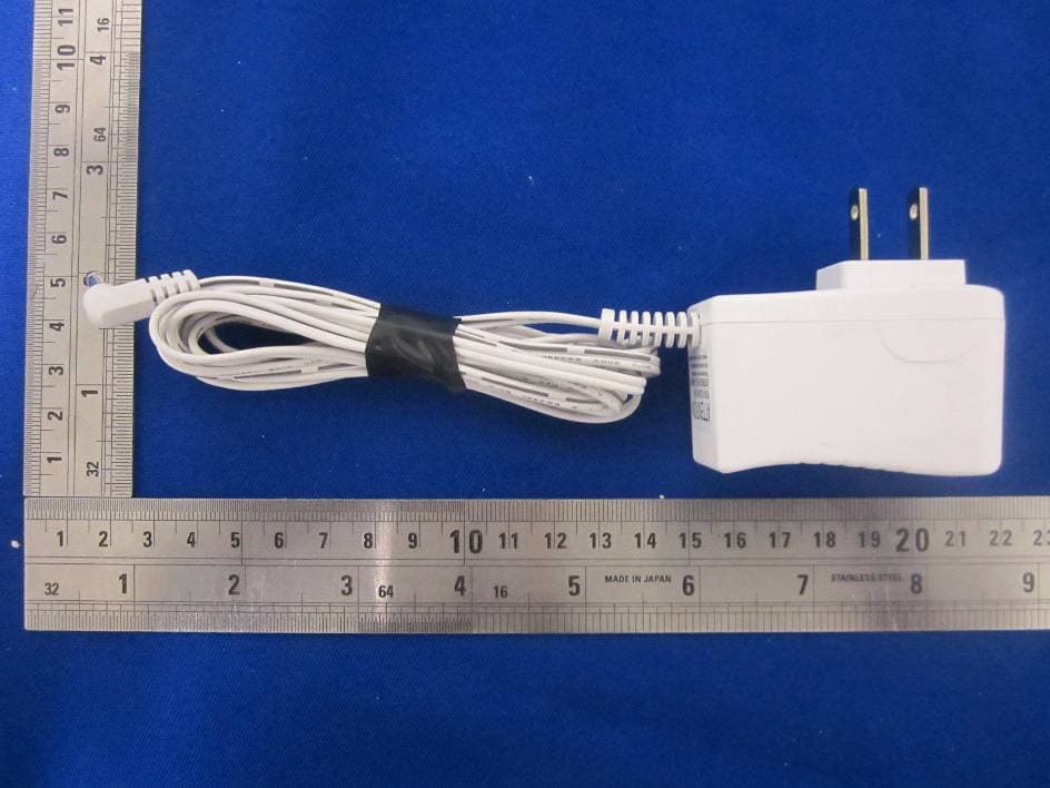
FCC ID.: DC9RC-20U Page A1 of A2 IC ID: 4012A-000000TD20U ETC Report No.: 10-01-MAS-173(R) ANNEX A: EXTERNAL CONSTRUCTION PHOTOS OF EUT 1. Outside view 1 of EUT 2. Outside view 2 of EUT FCC ID.: DC9RC-20U Page A2 of A2 IC ID: 4012A-000000TD20U ETC Report No.: 10-01-MAS-173(R) 3. Adapter 4. Adapter
Internal Photos
FCC ID.: DC9RC-20U Page B1 of B2 IC ID: 4012A-000000TD20U ETC Report No.: 10-01-MAS-173(R) ANNEX B: INTERNAL CONSTRUCTION PHOTOS OF EUT 1. Inside View 1 of EUT 2. Inside View 2 of EUT FCC ID.: DC9RC-20U Page B2 of B2 IC ID: 4012A-000000TD20U ETC Report No.: 10-01-MAS-173(R) 3. Front view of PCB 4. Rear view of PCB
Test Report
FCC ID.: DC9RC-20U Sheet 1 of 17 Sheets IC ID: 4012A-000000TD20U ETC Report No. : 10-01-MAS-173(R) Rev. No 1.0 CONFORMANCE TEST REPORT FOR FCC 47 CFR, Part 15 Subpart B and Canada RSS-210 Report No.: 10-01-MAS-173(R) Client: OPTEX CO, LTD. Product: CHIME BOX WITH RELAY RECEIVER Model: RC-20U FCC ID: DC9RC-20U IC ID: 4012A-000000TD20U Manufacturer/supplier: IQ Group Sdn. Bhd. Issue date of the origin report 09-11-MAS-081-02: 2009/11/16 Issue date of the revision report : 2010/03/24 The test result only corresponds to the tested sample. It is not permitted to copy this report, in part or in full, without the permission of the test laboratory. Total number of pages of this test report: 17 pages Total number of pages of photos: External photos 2 pages Internal photos 2 pages Setup photos 2 pages Test Engineer Checked By Approved By Perry Lin James Cheng Joe Hsieh ELECTRONICS TESTING CENTER, TAIWAN NO.8, LANE 29, WENMING RD., LESHAN TSUEN, GUISHAN SHIANG, TAOYUAN COUNTY, TAIWAN 33383, R.O.C. TEL: (03) 3276170~4 INT: +886-3-3276170~4 FAX: (03) 3276188 INT: +886-3-3276188 FCC ID.: DC9RC-20U Sheet 2 of 17 Sheets IC ID: 4012A-000000TD20U ETC Report No. : 10-01-MAS-173(R) Rev. No 1.0 Client : OPTEX CO, LTD. Address : 5-8-12, Ogoto Otsu Shiga 520-0101, Japan Manufacturer : IQ Group Sdn. Bhd. Address : 149, Jalan Sultan Azlan Shah, Taman Perindustrian Bayan Lepas, Fasa 1 (FTZ), Bayan Lepas, 11900 Pulau Pinang, Malaysia EUT : CHIME BOX WITH RELAY RECEIVER Trade name : OPTEX Model No. : RC-20U Power Source : Adapter (D41W090500-24/1) Input: 120VAC,60Hz,15W Output: 9V dc,500mA Regulations applied : FCC 47 CFR, Part 15 Subpart B (2008) Canada RSS-210 Issue 7 (2007) / RSS-Gen Issue 2 (2007) Test Specifications : Class B The testing described in this report has been carried out to the best of our knowledge and ability, and our responsibility is limited to the exercise of reasonable care. This certification is not intended to believe the sellers from their legal and/or contractual obligations. The compliance test is only certified for the test equipment and the results of the testing report relate only to the item tested. The compliance test of this report was conducted in accordance with the appropriate standards. It’s not intention to assure the quality and performance of the product. This report shall not be reproduced except in full, without the approval of ETC. This report must not be used by the client to claim product endorsement by NVLAP or any agency of the U.S. Government. Laboratory Introduction: Electronics Testing Center, Taiwan is recognized, filed and mutual recognition arrangement as following: 1 ISO9001: TüV Product Service 2 ISO/IEC 17025: BSMI, CNLA, NCC, NVLAP, CCIBLAC, UL, Compliance 3 Filing: FCC, Industry Canada, VCCI 4 MRA: Australia, Hong Kong, New Zealand, Singapore, USA, Japan, Korea, China, APLAC through TAF 5 FCC Registration Number: 90588, 91094, 91095 h Industry Canada Site Regisitation number: IC 2949A-1 NVLAP Lab Code 200133-0 FCC ID.: DC9RC-20U Sheet 3 of 17 Sheets IC ID: 4012A-000000TD20U ETC Report No. : 10-01-MAS-173(R) Rev. No 1.0 Table of Contents Page TABLE OF CONTENTS................................................................................................................... 3 1. GENERAL INFORMATION.............................................................................................. 4 1.1 Product Description .............................................................................................................. 4 1.2 Test Methodology ................................................................................................................. 4 1.3 Test Facility .......................................................................................................................... 4 1.4 Test Summary ...................................................................................................................... 4 2. PROVISIONS APPLICABLE ............................................................................................ 5 2.1 Definition .............................................................................................................................. 5 2.2 Requirement for Compliance ................................................................................................ 5 2.3 Labelling Requirement ......................................................................................................... 7 2.4 User Information................................................................................................................... 7 3. SYSTEM TEST CONFIGURATION................................................................................. 8 3.1 EUT configuration and operating ......................................................................................... 8 3.2 Devices for Tested System ...................................................................................................8 3.3 Deviation Statement.............................................................................................................. 8 3.4 Modification Record ............................................................................................................. 8 4. RADIATED EMISSION MEASUREMENT ..................................................................... 9 4.1 Applicable Standard.............................................................................................................. 9 4.2 Measurement Procedure .......................................................................................................9 4.3 Radiated Emission Data...................................................................................................... 11 4.4 Field Strength Calculation .................................................................................................. 12 4.5 Radiated Measuring Instrument...................................................................................…
Text truncated - open the document above for the full version.
Test Setup Photos
FCC ID.: DC9RC-20U Page 1 of 2 IC ID: 4012A-000000TD20U ETC Report No.: 10-01-MAS-173(R) Photos of Radiation Measuring Setup FCC ID.: DC9RC-20U Page 2 of 2 IC ID: 4012A-000000TD20U ETC Report No.: 10-01-MAS-173(R) Photos of Conduction Measuring Setup
Contact Information
Applicant
Hiroaki Nakamura(Manager, System Development Sec.)
Test Firm
Electronics Testing Center, TaiwanWinpo Tsai
Technical Specifications
| # | Rule Parts | Frequency Range | Power Output |
|---|---|---|---|
| 1 | 15B | 418 MHz - 418 MHz | - |
Other Applications from Optex Co Ltd
DC9IVP-GU
Aug 22, 2014Wireless Gateway
Equipment Class
DSS - Part 15 Spread Spectrum Transmitter
DC9-IVS166
Feb 26, 2014K-Band VCO Transceiver
Equipment Class
FDS - Part 15 Field Disturbance Sensor
DC9-VDS005
Feb 04, 2014Vehicle detection sensor
Equipment Class
DXX - Part 15 Low Power Communication Device Transmitter
DC9IVP-DU
Dec 29, 2013Door Camera Unit
Equipment Class
DSS - Part 15 Spread Spectrum Transmitter
DC9IVP-HU
Dec 29, 2013Handheld Monitor Unit
Equipment Class
DSS - Part 15 Spread Spectrum Transmitter