DGZCA3000Single Pole & Multi-Way Relay Type Wall Switch
Intermatic Inc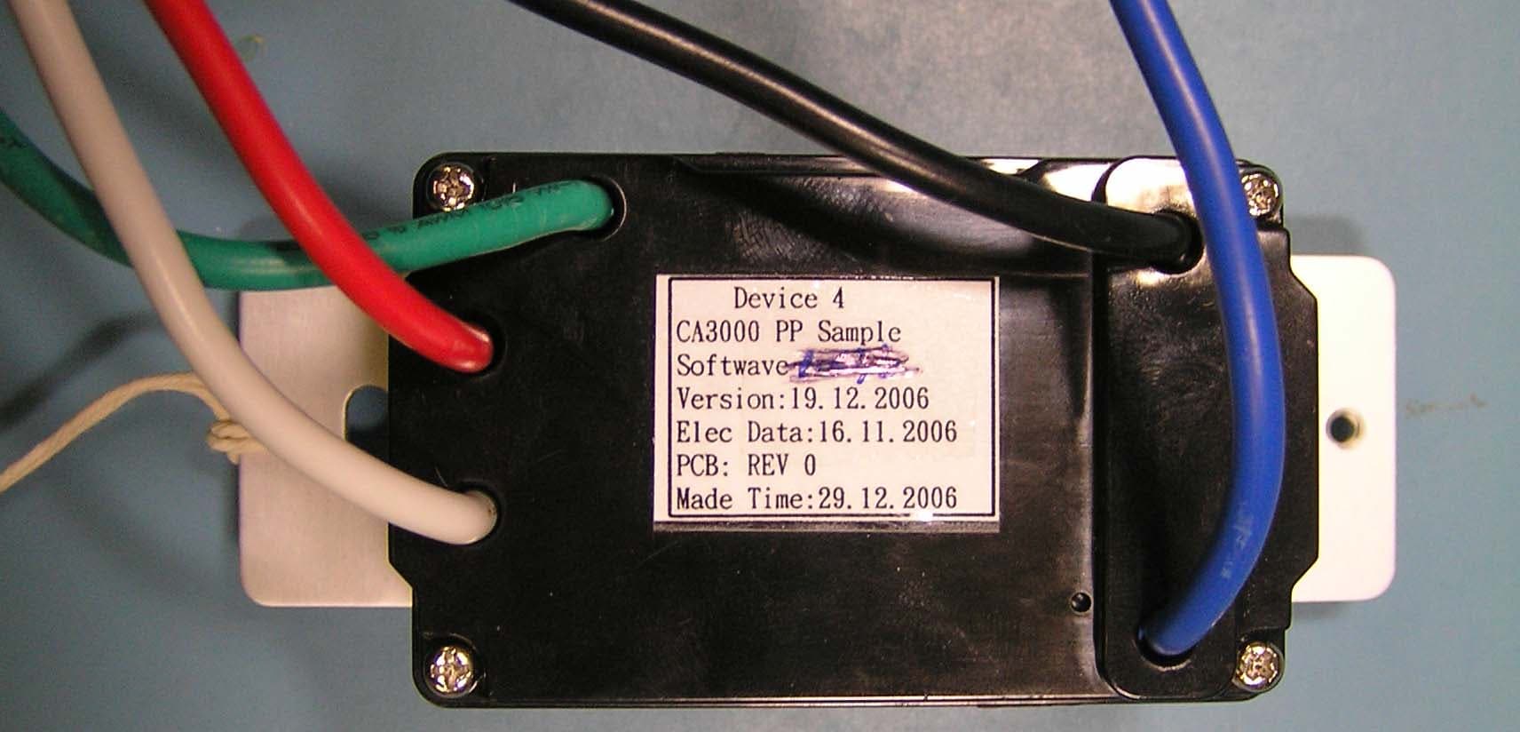
Click to zoom
Application Details
- Equipment Class
- DXX - Part 15 Low Power Communication Device Transmitter
- Date of Grant
- Mar 01, 2007
- Application Purpose
- Original Equipment
- Date of Application
- Mar 01, 2007
- Equipment Note
- Single Pole & Multi-Way Relay Type Wall Switch
- Frequency Range
- 908.40000000 - 908.44000000
- Company
- Intermatic Inc
- Country
- United States
Documents & Files
Document Text
Text extracted from the exhibit documents filed with the FCC. Open a document above to read the original.
Users Manual
Providing a Brighter Solution™ WARNING:Read instructions completely before installation and retain for future reference. WARNING: WARNING: OTHER CAUTIONS: For installation and/or use in accordance with appropriate electrical codes and regulations. Consult a qualified electrician for installation and operation. 1. Use only one (1) switch per load. For remote operation, use standard 3-way or 4-way electrical devices for ON/OFF operation or use with Z-Wave compatible control for wireless control from any location. 2. Disconnect power when servicing or changing load. 3. Use this device only with copper or copper clad wire. Model CA3000 Single Pole & Multi-Way Relay Type Wall Switch Specifications: Ratings: Colors: Connections: RF Information: Network Information: Single-Pole (One Location) or 3-Way (Multi-Location) or Wireless RF Control 120VAC, 50/60Hz 1800 Watts 15A Tungsten; 1800 Watts 15A Resistive/Inductive; 1800VA 15A Ballast; 1/2HP Motor Includes white, ivory, and light almond snap-on rocker plates. Black-Line, Blue-Load, Red-Traveler, White-Neutral, Green-Ground Minimum Range: 50ft indoor; 100ft outdoor Frequency: 908.42 MHz Mesh Network - Each line powered node acts as a repeater to route distant signals. Data Rate: 9600 bits/second Size: 232 Z-Wave™ Nodes Operating Temperature Range: 32°F (0°C) to 104°F (40°C) Power Consumption: 2.0W Max INSTALLATION: 1. WARNING: TO AVOID FIRE, SHOCK, OR DEATH, TURN OFF POWER AT CIRCUIT BREAKER AND TEST THAT POWER IS OFF BEFORE WIRING. Operation: 2. For retrofit applications, remove wall plate and disconnect switch. 3. Refer to wiring diagrams for proper connection of switch for intended application. 4. Check that all wire connections are secure. 5. Place all wires inside junction box. Install switch using (2) mounting screws furnished. Complete installation with a decorator style wall-plate. 6. Reconnect your electrical power. 7.Tap top of rocker to turn load on; tap bottom of rocker to turn load off. 8. For programming instructions refer to the(158CA12789).InTouch Installer & Users Guide The CA3000 Wall Switch is a Z-wave™ enabled device which is fully compatible with any Z-wave enabled network. Z-wave enabled devices display the Z-wave logo and guarantee connectivity and interoperability between devices. Each line powered node in a Z-wave network is designed to act as a repeater forming a mesh network eliminating radio “dead spots” and providing the highest level of reliability. - Mini-scenes allows local control of connected load plus up to 5 additional Z-wave enabled devices. - Switch always operates local load, and does not require central control system. Features - Multiple location On/Off when used with wireless accessory controls. - Multiple location On/Off control using conventional 3-way or 4-way wiring and devices. - Full 230 device scene control when used with Intermatic InTouch™ server (CA5500B). Rocker Color Conversion The frame and rocker color of this device can be converted to match interior design requirements. Simply use one of the included color plates (white, ivory, or light almond) and proceed as follows (please note that the device must be removed from the junction box to change the rocker, follow the installation instructions and warnings). 1. Select the color of the face you desire. 2. The frame has snaps on its sides. Using a small screwdriver or thumbnail, gently remove the frame and rocker from the housing body. 3. Take the new frame and position it properly to the housing body. Notice that the locking snaps will align in only the proper direction. Line up the plastic snaps with the slots in the housing body and snap into place. 4. The frame snaps in with an audible click. Ensure that both snaps are secure. Replace the device in the junction box following installation instructions. The color conversion is complete. Rocker Frame Snap This product is compatible with other Z-Waveenabled products™ FCC STATEMENT OF COMPLIANCE WARNING! Changes or modifications not expressly approved by Intermatic Inc. could void the user’s authority to operate the equipment. This device complies with part 15 of the FCC rules. Operation of this device is subject to the following two conditions: (1) This device may not cause harmful interference, and (2) This device must accept any interference, including interference that may cause undesired operation. NOTE: This equipment has been tested and found to comply with the limits for a Class B digital device, pursuant to Part 15 of the FCC Rules. These limits are designed to provide reasonable protection against harmful interference in a residential installation. This equipment generates, uses and can radiate radio frequency energy and, if not installed and used in accordance with the instructions, may cause harmful interference to radio communications. However, there is no guarantee that interference will not occur in a particular installation. If this equipment does cause harmful interference to radio or television reception, which can be determined by turning the equipment off and on, the user is encouraged to try to correct the interference by one or more of the following measures: -- Reorient or relocate the receiving antenna or device. -- Increase the separation between the equipment and receiver. -- Connect the equipment into an outlet on a circuit different from that to which the receiver is connected. -- Consult the dealer or an experienced radio/TV technician for help. 158CA12470REF WIRELESS CONTROLS TM White Single Pole Application HotBlack Neutral Blue Load Red Wire Connector Ground Green 120VAC 50/60 Hz 3-Way Application HotBlack Neutral Blue Red Wire Connector Ground Green 120VAC 50/60 Hz Jumper CA3000CA3000CA-3PS / Standard 3-Way Switch Multi-Way Application HotBlack Neutral Blue Load Red Wire Connector Ground Green 120VAC 50/60 Hz CA3000CA-3PS / Standard 3-Way SwitchCA-4PS / Standard 4-Way SwitchCA-3PS / Standard 3-Way SwitchCA-4PS / Standard 4-Way Switch LIMITED TEN YEAR WARRANTY If…
Text truncated - open the document above for the full version.
ID Label/Location Info
MODEL: CA3000 15A IN - WALL SWITCH 120Vac 50/60 Hz, 1800 W 15 A Tungsten, 15 A Resistive/Inductive, HP Motor FCC ID: DGZCA3000 IC: 4898A-CA3000 Refer to owners manual for complete instructions USE 75 ̊C COPPER WIRE ONLY SUITABLE FOR INDOOR USE ONLY. INTERMATIC INC., Spring Grove, IL 60081-9698 www.intermatic.com MADE IN CHINA PATENT(S) PENDING 1 2 CA3000 was154CA24917.qxp 4/10/06 1:21 PM Page 1
Test Report
Engineering Test Report No. 37624-02 Measurement of RF Interference from a Model CA3000 WALL SWITCH Transceiver For : Intermatic Spring Grove, IL P.O. No. : 925460 Date Received : January 15, 2007 Date Tested : January 15 through 17, 2007 Test Personnel : Richard E. King Specification : FCC "Code of Federal Regulations” Title 47 Part 15, Subpart B and Subpart C, Section 15.249 for Intentional Radiators Operating within the 902MHz to 928MHz band Test Report By : Richard E. King Approved By : Raymond J. Klouda Registered Professional Engineer of Illinois - 44894 Elite Electronic Engineering Inc. 1516 Centre Circle Downers Grove, IL 60515 Tel : (630) 495-9770 Fax: (630) 495-9785 www.elitetest.com Engineering Test Report No. 37624-02 THIS REPORT SHALL NOT BE REPRODUCED, EXCEPT IN FULL, WITHOUT THE WRITTEN APPROVAL OF ELITE ELECTRONIC ENGINEERING INC. Page 2 of 29 TABLE OF CONTENTS PARAGRAPH DESCRIPTION OF CONTENTS PAGE NO. 1.0 INTRODUCTION................................................................................................................................3 1.1 Description of Test Item................................................................................................................................3 1.2 Purpose.......................................................................................................................................................... 3 1.3 Deviations, Additions and Exclusions.......................................................................................................... 3 1.4 Applicable Documents.................................................................................................................................. 3 1.5 Subcontractor Identification.......................................................................................................................... 3 1.6 Laboratory Conditions................................................................................................................................. 3 2.0 TEST ITEM SETUP AND OPERATION.......................................................................................... 3 2.1 Power Input.................................................................................................................................................... 3 2.2 Grounding....................................................................................................................................................... 4 2.3 Peripheral Equipment.................................................................................................................................... 4 2.4 Interconnect Cables...................................................................................................................................... 4 2.5 Operational Mode.......................................................................................................................................... 4 2.6 Test Item Modifications...............................................................................................................................4 3.0 TEST EQUIPMENT............................................................................................................................ 4 3.1 Test Equipment List....................................................................................................................................... 4 3.2 Calibration Traceability................................................................................................................................4 3.3 Measurement Uncertainty........................................................................................................................... 4 4.0 REQUIREMENTS, PROCEDURES AND RESULTS..................................................................... 5 4.1 Powerline Conducted Emissions............................................................................................................... 5 4.1.1.1 Requirements................................................................................................................................5 4.2 Radiated Measurements............................................................................................................................. 6 4.2.1 Receiver................................................................................................................................................. 6 4.2.1.1 Requirements................................................................................................................................6 4.2.1.2 Procedures..................................................................................................................................... 6 4.2.1.3 Results............................................................................................................................................ 7 4.2.2 Transmitters........................................................................................................................................... 7 4.2.2.1 Requirements................................................................................................................................7 4.2.2.2 Procedures..................................................................................................................................... 8 4.2.2.3 Results............................................................................................................................................ 8 4.3 Occupied Bandwidth Measurements........................................................................................................ 9 4.3.1 Requirement.......................................................................................................................................... 9 4.3.2 Procedures...........................................................................................................................................…
Text truncated - open the document above for the full version.
Test Setup Photos
Engineering Test Report No. 37624-02 Page 13 of 29 Figure 2a - Receive at 908.4MHz Test Set-up for Conducted Emissions Figure 2b - Transmit at 908.4MHz Test Set-up for Conducted Emissions Engineering Test Report No. 37624-02 Page 14 of 29 Figure 3 - Transmit at 908.4MHz Test Set-up for Radiated Emissions 908.4MHz – Horizontal Polarization Test Set-up for Radiated Emissions 908.4MHz – Vertical Polarization
Contact Information
Applicant
Kimberly Boland(Director of Engineering)
Technical Contact
Intermatic, Inc.Bryan E Povish
[email protected]815-675-7751
7777 Winn Road · Spring Grove, Illinois · United States
Non-Technical Contact
Intermatic, Inc.Donna Marcil
[email protected]815-675-7777
Test Firm
Elite Electronic Engineering Inc.Kevin Halpin
Technical Specifications
| # | Rule Parts | Frequency Range | Power Output |
|---|---|---|---|
| 1 | 15C | 908.4 MHz - 908.44 MHz | - |
Other Applications from Intermatic Inc
DGZALC24B
Mar 17, 2024Programmable Switches
Equipment Class
DTS - Digital Transmission System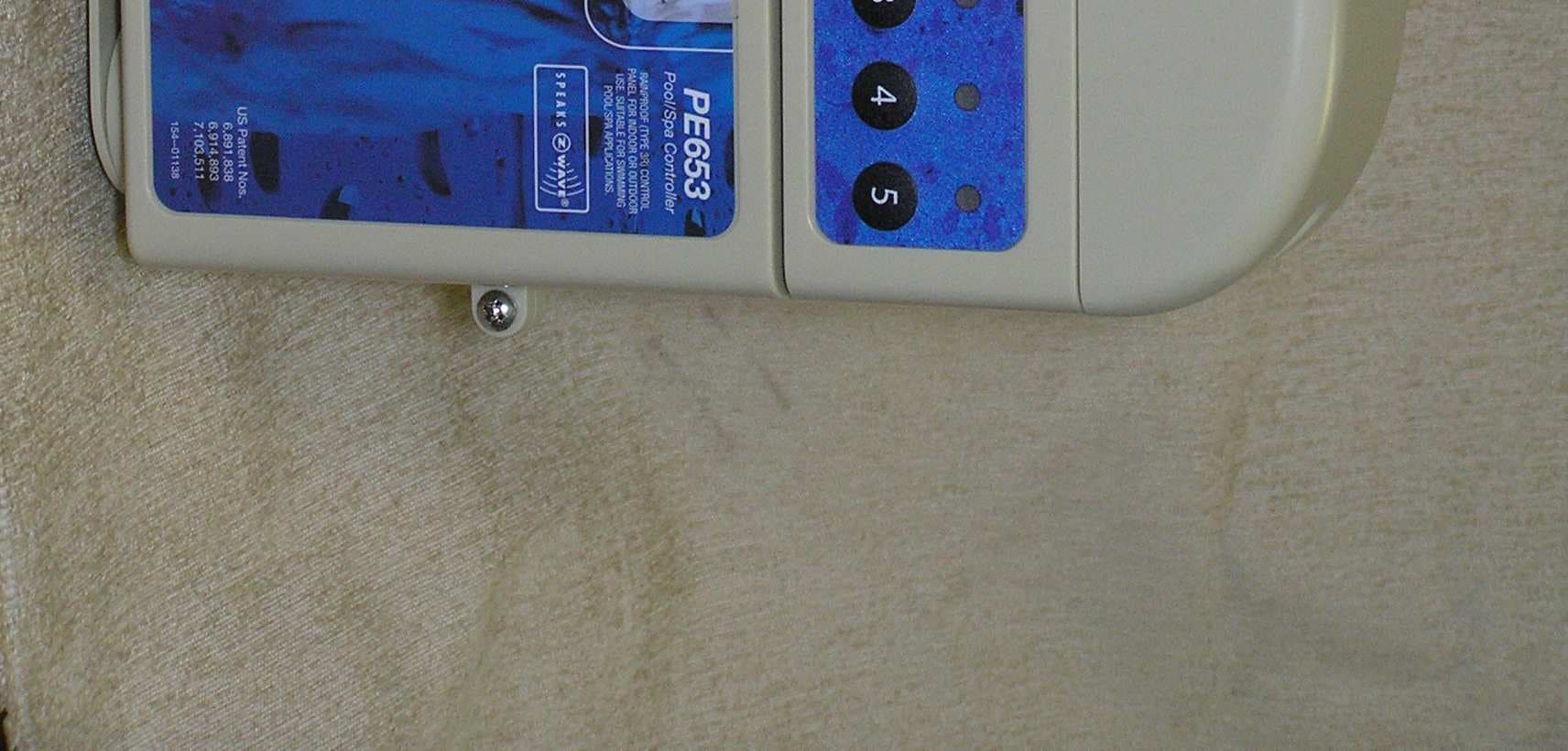
DGZPE000653
Apr 13, 20105 Circuit Digital Control
Equipment Class
DXT - Part 15 Low Power Transceiver, Rx Verified
DGZPE000953
Apr 13, 2010Hand Held Transceiver
Equipment Class
DXT - Part 15 Low Power Transceiver, Rx Verified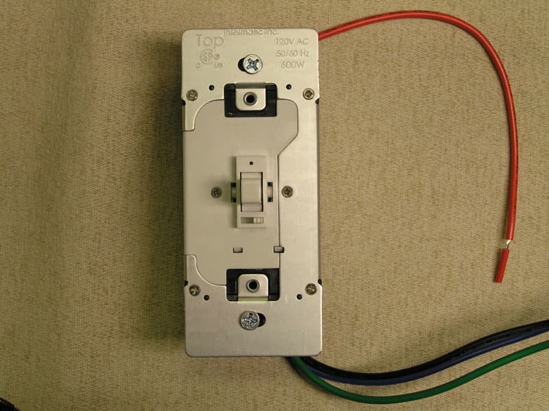
DGZHA000020P2
Mar 30, 2008In-Wall Toggle-Style Dimmer Switch
Equipment Class
DXX - Part 15 Low Power Communication Device Transmitter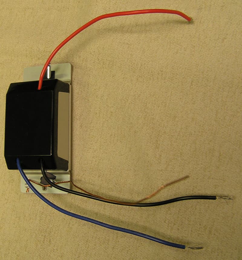
DGZHA000014P2
Mar 30, 2008In-Wall Dimmer Switch
Equipment Class
DXX - Part 15 Low Power Communication Device Transmitter