DGZCA3750Multi-Voltage High Current Contactor Module
Intermatic Inc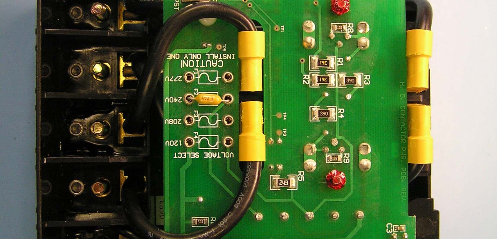
Click to zoom
Application Details
- Equipment Class
- DXX - Part 15 Low Power Communication Device Transmitter
- Date of Grant
- Oct 15, 2006
- Application Purpose
- Original Equipment
- Date of Application
- Oct 15, 2006
- Equipment Note
- Multi-Voltage High Current Contactor Module
- Frequency Range
- 908.40000000 - 908.40000000
- Company
- Intermatic Inc
- Country
- United States
Documents & Files
Document Text
Text extracted from the exhibit documents filed with the FCC. Open a document above to read the original.
Users Manual
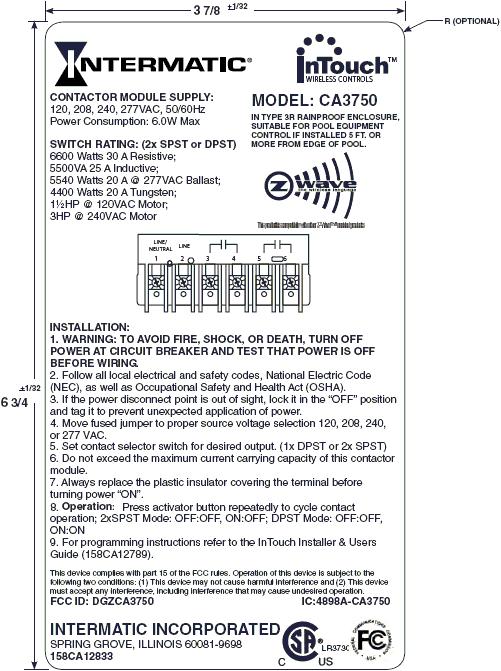
WARNING: WARNING: Read instructions completely before installation and retain for future reference. This device is not a motor disconnect. with 75°C rated copper or copper clad wire. WARNING: WARNING: OTHER CAUTIONS: For installation and/or use in accordance with appropriate electrical codes and regulations. Consult a qualified electrician for installation and operation. 1. For remote operation, use with Z-Wave compatible control for wireless control from any location. 2. Disconnect power when servicing or changing load. 3. Use this device only Note: For independent channel control requires presence of InTouch™ Server (CA5500B or other). Model CA3750 Multi-Voltage High Current Contactor Module Specifications: Ratings: Enclosure: Connections: RF Information: Network Information: Local control via Activator Button or Wireless RF Control 120, 208, 240, 277VAC, 50/60Hz 6600 Watts 30 A Resistive; 5500VA 25 A Inductive; 5540 Watts 20 A @ 277VAC Ballast; 4400 Watts 20 A Tungsten; 3HP @ 220VAC Motor NEMA 3R Indoor-Outdoor Polycarbonate Case. 1-Neutral/Line 2, 2-Line 1,3&4 Contact 1,5&6Contact 2 Minimum Range: 50ft indoor; 100ft outdoor Frequency: 908.42 MHz Mesh Network - Each line powered node acts as a repeater to route distant signals. Data Rate: 9600 bits/second Size: 232 Z-Wave™ Nodes Operating Temperature Range: 14°F (-10°C) to 140°F (60°C) Power Consumption: 6.0W Max INSTALLATION: 1. WARNING: TO AVOID FIRE, SHOCK, OR DEATH, TURN OFF POWER AT CIRCUIT BREAKER AND TEST THAT POWER IS OFF BEFORE WIRING. Operation: 2. Follow all local electrical and safety codes, National Electric Code (NEC), as well as Occupational Safety and Health Act (OSHA). 3. If the power disconnect point is out of sight, lock it in the “OFF” position and tag it to prevent unexpected application of power. 4. Move fused jumper to proper source voltage selection 120, 208, 240, or 277 VAC. 5. Set contact selector switch for desired output. (1x DPST or 2x SPST) 6. Do not exceed the maximum current carrying capacity of this contactor module. 7. Always replace the plastic insulator covering the terminal before turning power “ON”. 8.Press activator button repeatedly to cycle contact operation; 2xSPST Mode: OFF:OFF, ON:OFF; DPST Mode: OFF:OFF, ON:ON 7. For programming instructions refer to the(158CA12789).InTouch Installer & Users Guide The CA3750 Multi-Voltage High Current Contactor Module is a Z-wave™ enabled device which is fully compatible with any Z-wave enabled network. Z-wave enabled devices display the Z-wave logo and guarantee connectivity and interoperability between devices. Each node in a Z-wave network is designed to act as a repeater forming a mesh network eliminating radio “dead spots” and providing the highest level of reliability. - Multiple location ON/OFF control of contactor when used with wireless controls. - Multi-Voltage power supply 120, 208, 240, or 277 VAC - Field configurable outputs 2 independently controllable SPST contacts or simultaneous DPST contact operation. - Up-front activator switch always operates load, does not require central control system. Features 123456 LINE LINE/ NEUTRAL Program Button Input / Output Terminals Status LED Supply Terminals This product is compatible with other Z-Waveenabled products™ Providing a Brighter Solution™ 158CA12473 WIRELESS CONTROLS TM Standard Installation FCC STATEMENT OF COMPLIANCE WARNING! Changes or modifications not expressly approved by Intermatic Inc. could void the user’s authority to operate the equipment. This device complies with part 15 of the FCC rules. Operation of this device is subject to the following two conditions: (1) This device may not cause harmful interference, and (2) This device must accept any interference, including interference that may cause undesired operation. NOTE: This equipment has been tested and found to comply with the limits for a Class B digital device, pursuant to Part 15 of the FCC Rules. These limits are designed to provide reasonable protection against harmful interference in a residential installation. This equipment generates, uses and can radiate radio frequency energy and, if not installed and used in accordance with the instructions, may cause harmful interference to radio communications. However, there is no guarantee that interference will not occur in a particular installation. If this equipment does cause harmful interference to radio or televisionreception, which can be determined by turning the equipment off and on, the user is encouraged to try to correct the interference by one or more of the following measures: -- Reorient or relocate the receiving antenna or device. -- Increase the separation between the equipment and receiver. -- Connect the equipment into an outlet on a circuit different from that to which the receiver is connected. -- Consult the dealer or an experienced radio/TV technician for help. 123456 Line 1 Line 2 / Neutral LOADLOAD 123456 Line 1 Line 2 / Neutral Use jumpers only if device voltage and output voltage are the same. LOADLOAD 123456 Line 1 Line 2 / Neutral Use jumpers only if device voltage and output voltage are the same. LOAD 123456 Line 1 Line 2 / Neutral LOAD This product is compatible with other Z-Waveenabled products™ LIMITED TEN YEAR WARRANTY If within ten (10) years from date of purchase, this product fails due to a defect in material or workmanship, Intermatic Incorporated will repair or replace, at its sole option. This warranty applies only to the original purchaser and is not transferable. This warranty excludes and this is disclaimed liability for labor for removal of this product or reinstallation. The warranty does not apply to: (a) damage caused by accident, abuse, mishandling, dropping, acts of God, or any negligent use; (b) units which have been subject to unauthorized repair, opened, taken apart, or otherwise modified; (c) units not used in accordancewith directions; (d) damages exceeding the cost of the product. Some states do not allow a limitation of damages…
Text truncated - open the document above for the full version.
Test Report
Engineering Test Report No. 35770-01 Measurement of RF Interference from a Model CA3750 Transceiver For : Intermatic Spring Grove, IL P.O. No. : 912511 Date Received : October 13, 2005 Date Tested : October 13, 2005 through October 14, 2005 Test Personnel : Mark E. Longinotti, NARTE® Certified EMC Test Engineer, ATL-0154-E Specification : FCC "Code of Federal Regulations” Title 47 Part 15, Subpart B and Subpart C, Section 15.249 for Intentional Radiators Operating within the 902MHz to 928MHz band Test Report By : Mark E. Longinotti NARTE® Certified EMC Test Engineer, ATL-0154-E Approved By : Raymond J. Klouda Registered Professional Engineer of Illinois - 44894 Elite Electronic Engineering Inc. 1516 Centre Circle Downers Grove, IL 60515 Tel : (630) 495-9770 Fax: (630) 495-9785 www.elitetest.com Engineering Test Report No. 35770-01 THIS REPORT SHALL NOT BE REPRODUCED, EXCEPT IN FULL, WITHOUT THE WRITTEN APPROVAL OF ELITE ELECTRONIC ENGINEERING INC. Page 2 of 32 TABLE OF CONTENTS PARAGRAPH DESCRIPTION OF CONTENTS PAGE NO. 1.0 INTRODUCTION................................................................................................................................. 3 1.1 Description of Test Item.................................................................................................................................... 3 1.2 Purpose............................................................................................................................................................. 3 1.3 Deviations, Additions and Exclusions ............................................................................................................... 3 1.4 Applicable Documents ...................................................................................................................................... 3 1.5 Subcontractor Identification .............................................................................................................................. 3 1.6 Laboratory Conditions..................................................................................................................................... 3 2.0 TEST ITEM SET-UP AND OPERATION............................................................................................3 2.1 Power Input...................................................................................................................................................... 4 2.2 Grounding......................................................................................................................................................... 4 2.3 Peripheral Equipment........................................................................................................................................ 4 2.4 Interconnect Cables........................................................................................................................................... 4 2.5 Operational Mode ............................................................................................................................................. 4 2.6 Test Item Modifications................................................................................................................................... 4 3.0 TEST EQUIPMENT.............................................................................................................................. 4 3.1 Test Equipment List .......................................................................................................................................... 4 3.2 Calibration Traceability ...................................................................................................................................4 3.3 Measurement Uncertainty................................................................................................................................4 4.0 REQUIREMENTS, PROCEDURES AND RESULTS.......................................................................... 5 4.1 Powerline Conducted Emissions ..................................................................................................................... 5 4.1.1 Receiver.................................................................................................................................................... 5 4.1.1.1 Requirements .................................................................................................................................... 5 4.1.1.2 Procedures.........................................................................................................................................5 4.1.1.3 Results...............................................................................................................................................5 4.1.2 Transmitter ............................................................................................................................................... 6 4.1.2.1 Requirements .................................................................................................................................... 6 4.1.2.2 Procedures.........................................................................................................................................6 4.1.2.3 Results...............................................................................................................................................6 4.2 Radiated Measurements................................................................................................................................... 7 4.2.1 Receiver.................................................................................................................................................... 7 4.2.1.1 Requirements .................................................................................................................................... 7 4.2.1.2 Procedures................................................…
Text truncated - open the document above for the full version.
Test Setup Photos
Engineering Test Report No. 35770-01 Page 13 of 32 Figure 2 Test Set-up for Conducted Emissions – Receive at 908.3MHz Test Set-up for Conducted Emissions – Transmit at 908.4MHz Engineering Test Report No. 35770-01 Page 14 of 32 Figure 3a - Receive at 908.3MHz Test Set-up for Radiated Emissions, 908.3MHz – Horizontal Polarization Test Set-up for Radiated Emissions, 908.3MHz – Vertical Polarization Engineering Test Report No. 35770-01 Page 15 of 32 Figure 3b - Receive at 908.3MHz Test Set-up for Radiated Emissions, 1GHz to 5GHz – Horizontal Polarization Test Set-up for Radiated Emissions, 908.3MHz – Vertical Polarization Engineering Test Report No. 35770-01 Page 16 of 32 Figure 3c - Transmit at 908.4MHz Test Set-up for Radiated Emissions 908.4MHz – Horizontal Polarization Test Set-up for Radiated Emissions 908.4MHz – Vertical Polarization Engineering Test Report No. 35770-01 Page 17 of 32 Figure 3d - Transmit at 908.4MHz Test Set-up for Radiated Emissions, 1GHz to 9.1GHz – Horizontal Polarization Test Set-up for Radiated Emissions, 1GHz to 9.1GHz – Vertical Polarization
Contact Information
Applicant
Kimberly Boland(Director of Engineering)
Technical Contact
Intermatic, Inc.Bryan E. Povish
[email protected]815-675-7751
7777 Winn Road · Spring Grove, Illinois · United States
Non-Technical Contact
Intermatic, Inc.Donna Marcil
[email protected]815-675-7777
Test Firm
Elite Electronic Engineering Inc.Kevin Halpin
Technical Specifications
| # | Rule Parts | Frequency Range | Power Output |
|---|---|---|---|
| 1 | 15C | 908.4 MHz - 908.4 MHz | - |
Other Applications from Intermatic Inc
DGZALC24B
Mar 17, 2024Programmable Switches
Equipment Class
DTS - Digital Transmission System
DGZPE000653
Apr 13, 20105 Circuit Digital Control
Equipment Class
DXT - Part 15 Low Power Transceiver, Rx Verified
DGZPE000953
Apr 13, 2010Hand Held Transceiver
Equipment Class
DXT - Part 15 Low Power Transceiver, Rx Verified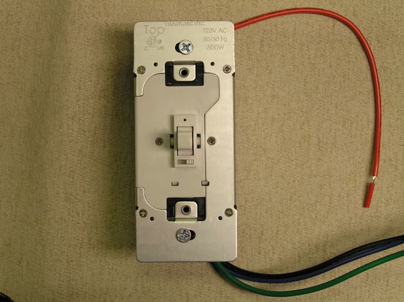
DGZHA000020P2
Mar 30, 2008In-Wall Toggle-Style Dimmer Switch
Equipment Class
DXX - Part 15 Low Power Communication Device Transmitter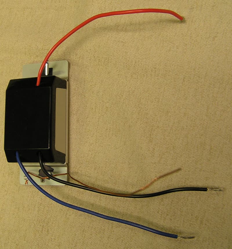
DGZHA000014P2
Mar 30, 2008In-Wall Dimmer Switch
Equipment Class
DXX - Part 15 Low Power Communication Device Transmitter