DGZH0006In-Wall Dimmer
Intermatic Inc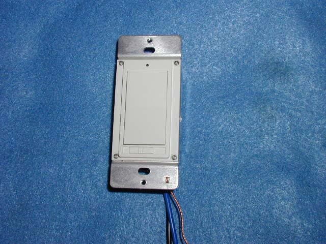
Click to zoom
Application Details
- Equipment Class
- DXT - Part 15 Low Power Transceiver, Rx Verified
- Date of Grant
- Aug 03, 2004
- Application Purpose
- Original Equipment
- Date of Application
- Aug 03, 2004
- Equipment Note
- In-Wall Dimmer
- Frequency Range
- 908.42000000 - 908.42000000
- Company
- Intermatic Inc
- Country
- United States
Documents & Files
Document Text
Text extracted from the exhibit documents filed with the FCC. Open a document above to read the original.
Users Manual
-------------------------------------- DRAFT COPY -------------------------------------- Instructions for Model HA06 – In-wall Dimmable Switch – using the HA07 Controller <Front cover> User’s Manual *Illustration of HA06 In-wall Dimmable Switch* <Inside cover> General Description Federal Communications Commission Statement This device complies with part 15 of the FCC rules. Operation of this device is subject to the following two conditions: (1) This device may not cause harmful interference, and (2) This device must accept any interference, including interference that may cause undesired operation. NOTE: This equipment has been tested and found to comply with the limits for a Class B digital device, pursuant to Part 15 of the FCC Rules. These limits are designed to provide reasonable protection against harmful interference in a residential installation. This equipment generates, uses and can radiate radio frequency energy and, if not installed and used in accordance with the instructions, may cause harmful interference to radio communications. However, there is no guarantee that interference will not occur in a particular installation. If this equipment does cause harmful interference to radio or television reception, which can be determined by turning the equipment off and on, the user is encouraged to try to correct the interference by one or more of the following measures: -- Reorient or relocate the receiving antenna or device. -- Increase the separation between the equipment and receiver. -- Connect the equipment into an outlet on a circuit different from that to which the receiver is connected. -- Consult the dealer or an experienced radio/TV technician for help. WARNING! Changes or modifications not expressly approved by the party responsible for compliance could void the user’s authority to operate the equipment. Enclosed you will find: 1 Indoor In-wall Dimmer (for use with HA07, HA09, or any Z-wave enabled remote controller) Installation Instructions In-wall Dimmer Switch: 1. Hard-wire the In-wall switch to a 125VAC supply using the black wire lead. 2.Hard-wire the In-wall switch to a load you wish to control using the blue wire lead. Maximum rating of the load branch should not exceed 300 Watts. Remote Controller 1. Open the battery compartment located on the back of the remote controller by pressing down on the battery compartment tab and pulling the door outward. 2. Insert 4 “AA” alkaline batteries (not included) with polarities as shown. 3. Replace the battery compartment by first inserting the 2 tabs at the bottom of the door, then pressing the door in until the door ‘clicks’ shut. Operating Instructions Creating a Network 1. On the remote controller, the include button is located behind a protective lid. Raise the lid to gain access to the Include and Exclude buttons. 2. Press and release the include button. The INCLude icon in the LCD display will begin to flash indicating that the controller is ready to register modules. 3. On the In-wall switch, press and release the top half of the rocker switch (the ON switch). If successful, the “INCL” icon on the controller will stop flashing and the word “SUCCESSFUL” will turn on steady in the LCD display for 2 seconds. If not successful, the words “NOT SUCCESSFUL” will turn on steady in the LCD display for 2 seconds. 4. Repeat steps 2 & 3 for each module you wish to add to the network. Assigning Modules to Channels 1. On the remote controller, press and hold the ON and OFF buttons for the channel to which you want to assign a module at the same time. After about 3 seconds, the word, “LEARN” will be displayed in the LCD display. This indicates that the controller is ready to assign a module to that channel. You may now release the ON and OFF buttons. 2. Press and hold the Include button. The INCLude icon will turn on. 3. While still holding the Include button in step 3, press and release the top half of the rocker switch (the ON switch). Do not release the Include button on the controller yet. 4. Choose a light level by pressing and holding, or pressing and releasing the ON or OFF switch on the In-wall switch. Possible settings are FULL ON, FULL OFF, and DIMMED. 5. After reaching your desired light level, release the Include button on the remote controller. The remote controller will automatically store the light level that you have just set. The word “SUCCESSFUL” will turn on for 2 seconds and the module is now associated to that channel with a default light level assigned. Remotely turning ON and OFF or dimming a module 1. To turn ON a module, press and release the ON button for that module’s given channel. 2. To turn OFF a module, press and release the OFF button on for that module’s given channel. 3. To dim a module up, press and hold the ON button. To dim a module down, press and hold the OFF button. Model HA06 – In-wall Dimmable Switch – Specifications Range:>50 feet Ratings:120VAC @ 60Hz, 300W tungsten max., 2.5 Amps Tungsten Suitable for indoor use only. This device complies with part 15 of the FCC rules. Operation of this device is subject to the following two conditions: (1) This device may not cause harmful interference, and (2) This device must accept any interference, including interference that may cause undesired operation. For control of incandescent luminaries only. Pour commande de luminaries a incandescence seulement.
Cover Letter(s)
Letter of Agency Date: July 28, 2004 American Telecommunications Certification Body, Inc. 6731 Whittier Avenue Suite C110 McLean, VA 22101 To Whom It May Concern: Please be advised that Intermatic, Inc. authorizes D.L.S. Electronic Systems, Inc. to act on our behalf, until otherwise notified, for applications submitted to American Telecommunications Certification Body, Inc. (ATCB). We certify that we are not subject to denial of federal benefits, that includes FCC benefits, pursuant to Section 5301 of the Anti-Drug Abuse ACT of 1988, U.S.C. 862. Further, no party, as defined in 47 CFR 1.2002(b), to the application is subject to denial of federal benefits, that includes FCC benefits. Thank you for your attention to this matter. Signatory, Arnom C. Rowe EMC ENGINEER EMC-001375-NE D.L.S. Electronic Systems, Inc. FCC Labeling Requirements and Information Date: July 28, 2004 American Telecommunications Certification Body, Inc. 6731 Whittier Avenue Suite C110 McLean, VA 22101 RE: FCC Labeling Requirements FCC ID: DGZH0006 The following label information is required by the FCC Rules and Regulations for certified devices. Also attached, please find marketing information required by the FCC Rules and Regulations. Thank you for your attention to these matters. Sincerely, Arnom C. Rowe EMC ENGINEER EMC-001375-NE D.L.S. Electronic Systems, Inc. Request for Confidentiality Date: July 28, 2004 American Telecommunications Certification Body, Inc. 6731 Whittier Avenue Suite C110 McLean, VA 22101 RE: Certification Application FCC ID: DGZH0006 Please be advised that the following information is to be held confidential and behalf of APPLICANT NAME: • Block Diagram • Schematics The application contains technical information which Intermatic, Inc. deems to be trade secrets and proprietary. If made public, the information might be used to the disadvantage of the applicant in the market place. Thank you for your attention to this matter. Signatory Arnom C. Rowe EMC ENGINEER EMC-001375-NE D.L.S. Electronic Systems, Inc. Modification Letter Date: July 28, 2004 American Telecommunications Certification Body, Inc. 6731 Whittier Avenue Suite C110 McLean, VA 22101 RE: Certification Application FCC ID: DGZH0006 Please be advised that the following information is a list of modifications that will be included in the production process for the above-referenced equipment. Change 1: There were no modifications made during testing. Change 2: Change 3: Change 4: Change 5: Change 6: Change 7: Change 8: Change 9 Change 10: Thank you for your attention to this matter. Signatory Arnom C. Rowe EMC ENGINEER EMC-001375-NE D.L.S. Electronic Systems, Inc. Manufacturer’s Letter Date: July 28, 2004 American Telecommunications Certification Body, Inc. 6731 Whittier Avenue Suite C110 McLean, VA 22101 RE: Certification Application FCC ID: DGZH0006 To Whom It May Concern: Please be advised that the manufacturer will ensure that the above-referenced model will be manufactured in accordance with the FCC Rules and Regulations. Thank you for your attention to this matter. Signatory Arnom C. Rowe EMC ENGINEER EMC-001375-NE D.L.S. Electronic Systems, Inc.
Cover Letter(s)
FCC ID: DGZH0006 D.L.S. ELECTRONIC SYSTEMS, INC. 1250 Peterson Drive Wheeling, Illinois 60090 FCC Authorization & Evaluation Division 7435 Oakland Mills Road Columbia, Maryland 21045-0429 Gentlemen: We are submitting for Intermatic, Inc., Inc., a In-Wall DimmerTransmitter, Model Number HA06, with a FCC ID: DGZH0006 for Certification. This unit has been tested and complies to Part 15, Subpart C. If there are any questions in regards to this application, please call D.L.S. Electronic Systems, Inc. at (847) 537 6400. Enclosed you will find a copy of our test report with the information and results of tests that is required under Part 15, Section 15.249. Thank you for your assistance in this matter. Sincerely, Arnom C. Rowe EMC-001375-NE DLS/mm
ID Label/Location Info
MODEL: HA06In-Wall Dimmer 120Vac at 60 Hz, 300 Watts Tungsten FCC ID DGZH0006 IC: 4898A-H0006 This device complies with part 15 of the FCC rules. Operation of this device is subject to the following two conditions: (1) This device may not cause harmful interference, and (2) This device must accept any interference, including interference FOR CONTROL OF PERMANENTLY INSTALLED INCANDESCENT LAMP FIXTURES ONLY SUITABLE FOR UP TO 2 GANG INSTALLATIONS Patent(s) Pending INTERMATIC INC., Spring Grove, IL 60081-9698 www.intermatic.com MADE IN CHINA 154HA23823 154HA23823 7/20/04 2:55 PM Page 1
Internal Photos
RF Shielding Removed RF Shielding Removed
Test Report
1250 Peterson Dr., Wheeling, IL 60090 Company: Intermatic Inc. Model Tested: HA06 Report Number: 10549 FCC Rules and Regulations / Intentional Radiators Operational in the 902-928 MHz, 2400-2483.5 MHz, 5725-5875 MHz, and 24.0-24.25 GHz Bands Part 15, Subpart C, Section 15.249 THE FOLLOWING ''MEETS'' THE ABOVE TEST SPECIFICATION Formal Name: In-Wall Dimmer Kind of Equipment: Wall Switch Test Configuration: Hard-wired installation (Tested at 120 vac, 60 Hz) Model Number(s): HA06 Model(s) Tested: HA06 Serial Number(s): NA Date of Tests: January 26, 27 & 28, 2004 Test Conducted For: Intermatic Inc. 7777 Winn Road Spring Grove, IL 60081 NOTICE: “This report must not be used by the client to claim product endorsement by NVLAP or any agency of the U.S. Government”. Please see the "Additional Description of Equipment Under Test" page listed inside of this report. This report must not be reproduced (except in full), without the approval of D.L.S. Electronic Systems. Page - 1 - 1250 Peterson Dr., Wheeling, IL 60090 Company: Intermatic Inc. Model Tested: HA06 Report Number: 10549 SIGNATURE PAGE Report By: Arnom C. Rowe Test Engineer EMC-001375-NE Reviewed By: William Stumpf OATS Manager Approved By: Brian Mattson General Manager Company Official: Intermatic Inc. Page - 2 - 1250 Peterson Dr., Wheeling, IL 6009 Company: Intermatic Inc. Model Tested: HA06 Report Number: 10549 Page -3- 1250 Peterson Dr., Wheeling, IL 6009 Company: Intermatic Inc. Model Tested: HA06 Report Number: 10549 Page -4- 1250 Peterson Dr., Wheeling, IL 6009 Page -4- Company: Intermatic Inc. Model Tested: HA06 Report Number: 10549 1250 Peterson Dr., Wheeling, IL 6009 Page -5- Company: Intermatic Inc. Model Tested: HA06 Report Number: 10549 1250 Peterson Dr., Wheeling, IL 6009 Company: Intermatic Inc. Model Tested: HA06 Report Number: 10549 Page -6- 1250 Peterson Dr., Wheeling, IL 6009 Company: Intermatic Inc. Model Tested: HA06 Report Number: 10549 Page -7- 1250 Peterson Dr., Wheeling, IL 6009 Company: Intermatic Inc. Model Tested: HA06 Report Number: 10549 Page -8- 1250 Peterson Dr., Wheeling, IL 6009 Company: Intermatic Inc. Model Tested: HA06 Report Number: 10549 Page -9- 1250 Peterson Dr., Wheeling, IL 6009 Company: Intermatic Inc. Model Tested: HA06 Report Number: 10549 Page -10- 1250 Peterson Dr., Wheeling, IL 6009 Company: Intermatic Inc. Model Tested: HA06 Report Number: 10549 Page -11- 1250 Peterson Dr., Wheeling, IL 6009 Company: Intermatic Inc. Model Tested: HA06 Report Number: 10549 Page -12- 1250 Peterson Dr., Wheeling, IL 6009 Company: Intermatic Inc. Model Tested: HA06 Report Number: 10549 TABLE OF CONTENTS i. Cover Page..........................................................................................................................................1 ii. Signature Page....................................................................................................................................2 iii. NVLAP Certificate of Accreditation..............................................................................................3 iv. NVLAP Scope of Accreditation.....................................................................................................4 v. Table of Contents..............................................................................................................................13 1.0 Summary of Test Report...............................................................................................................14 2.0 Introduction...................................................................................................................................14 3.0 Object............................................................................................................................................14 4.0 Test Set-Up...................................................................................................................................15 5.0 Test Equipment.............................................................................................................................16 6.0 Ambient Measurements................................................................................................................17 7.0 Description of Test Sample...........................................................................................................18 8.0 Additional Description of Test Sample......................................................................................... 21 9.0 Photo Information and Test Set-Up..............................................................................................22 10.0 Radiated Photos Taken During Testing........................................................................................ 23 10.0 Conducted Photos Taken During Testing.....................................................................................24 11.0 Results of Tests.............................................................................................................................25 12.0 Conclusion....................................................................................................................................25 TABLE 1 – EQUIPMENT LIST..............................................................................................................26 Appendix A – Electric Field Radiated Emissions Test............................................................................. 28 1.0 Conducted Emission Measurements............................................................................................. 29 1.0 Conducted Data and Graph(s) taken during testing......................................................................30 2.0 Band Edge and Restrict Band Compliance...................................................................................37 3.0 Field Strength of Spurious Emission Measurements....................................................................38 3.0 Radiated Data and Gra…
Text truncated - open the document above for the full version.
Contact Information
Applicant
Kimberly Boland(Director of Engineering)
Technical Contact
D. L. S. Electronic Systems, Inc.Arnom Rowe
[email protected]847-537-6400
1250 Peterson Drive · Wheeling, Illinois · United States
Test Firm
D.L.S. Electronic Systems, Inc.Brian Mattson
Technical Specifications
| # | Rule Parts | Frequency Range | Power Output |
|---|---|---|---|
| 1 | 15C | 908.42 MHz - 908.42 MHz | - |
Other Applications from Intermatic Inc
DGZALC24B
Mar 17, 2024Programmable Switches
Equipment Class
DTS - Digital Transmission System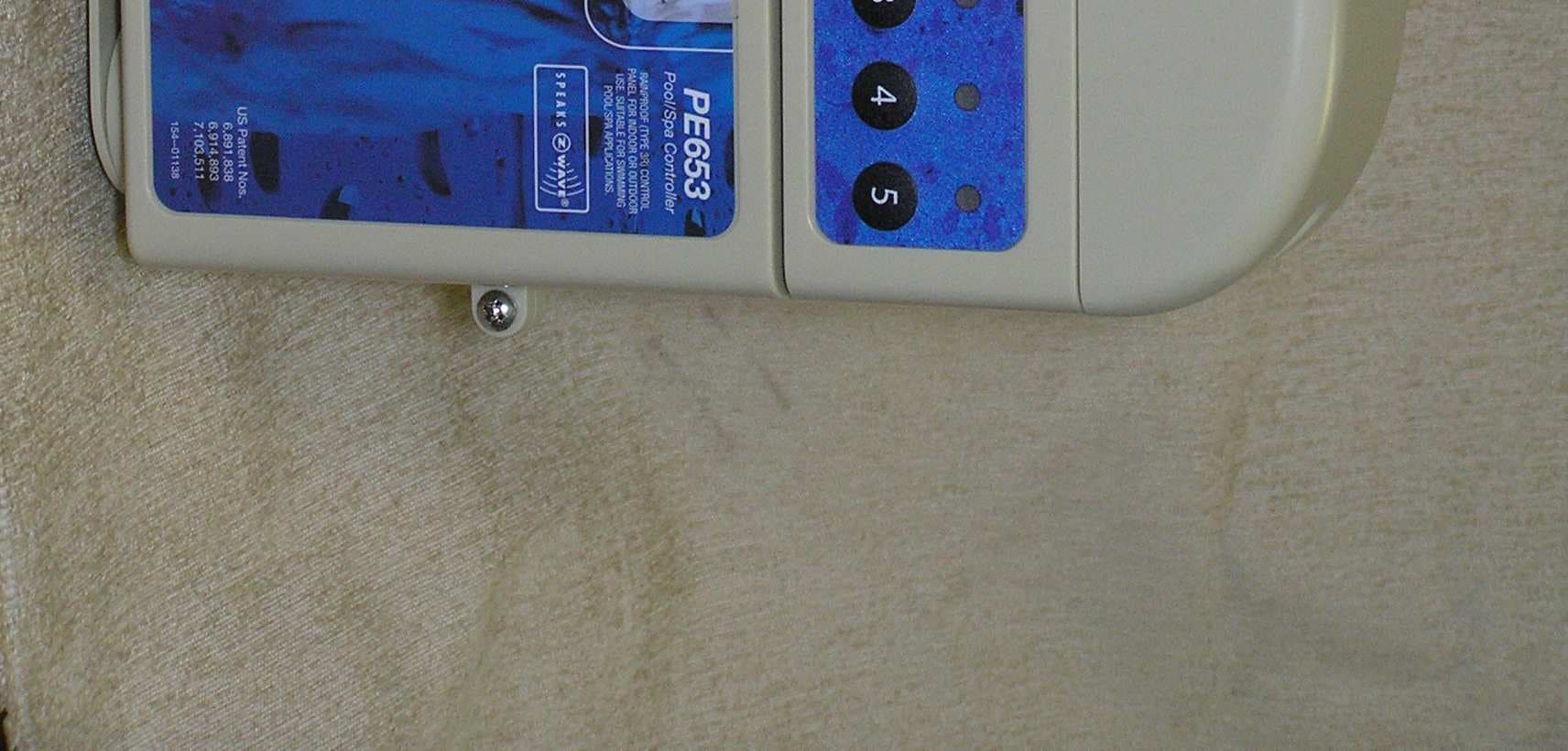
DGZPE000653
Apr 13, 20105 Circuit Digital Control
Equipment Class
DXT - Part 15 Low Power Transceiver, Rx Verified
DGZPE000953
Apr 13, 2010Hand Held Transceiver
Equipment Class
DXT - Part 15 Low Power Transceiver, Rx Verified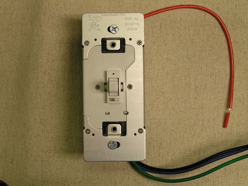
DGZHA000020P2
Mar 30, 2008In-Wall Toggle-Style Dimmer Switch
Equipment Class
DXX - Part 15 Low Power Communication Device Transmitter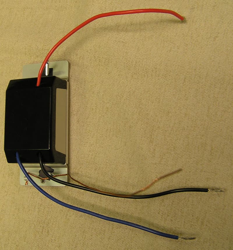
DGZHA000014P2
Mar 30, 2008In-Wall Dimmer Switch
Equipment Class
DXX - Part 15 Low Power Communication Device Transmitter