DGZH0009Handy Remote Controller
Intermatic Inc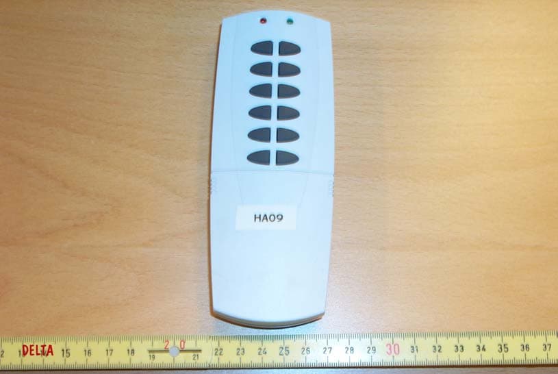
Click to zoom
Application Details
- Equipment Class
- DXT - Part 15 Low Power Transceiver, Rx Verified
- Date of Grant
- Mar 16, 2004
- Application Purpose
- Original Equipment
- Date of Application
- Mar 16, 2004
- Equipment Note
- Handy Remote Controller
- Frequency Range
- 908.42000000 - 908.42000000
- Company
- Intermatic Inc
- Country
- United States
Documents & Files
Document Text
Text extracted from the exhibit documents filed with the FCC. Open a document above to read the original.
Users Manual
-------------------------------------- DRAFT COPY -------------------------------------- Instructions for Model HA09 – Handy Remote Controller <Front cover> User’s Manual *Illustration of HA09 controller* <Inside cover> General Description Federal Communications Commission Statement This device complies with part 15 of the FCC rules. Operation of this device is subject to the following two conditions: (1) This device may not cause harmful interference, and (2) This device must accept any interference, including interference that may cause undesired operation. NOTE: This equipment has been tested and found to comply with the limits for a Class B digital device, pursuant to Part 15 of the FCC Rules. These limits are designed to provide reasonable protection against harmful interference in a residential installation. This equipment generates, uses and can radiate radio frequency energy and, if not installed and used in accordance with the instructions, may cause harmful interference to radio communications. However, there is no guarantee that interference will not occur in a particular installation. If this equipment does cause harmful interference to radio or television reception, which can be determined by turning the equipment off and on, the user is encouraged to try to correct the interference by one or more of the following measures: -- Reorient or relocate the receiving antenna or device. -- Increase the separation between the equipment and receiver. -- Connect the equipment into an outlet on a circuit different from that to which the receiver is connected. -- Consult the dealer or an experienced radio/TV technician for help. WARNING! Changes or modifications not expressly approved by the party responsible for compliance could void the user’s authority to operate the equipment. Enclosed you will find: 1 Handy Remote Controller Installation Instructions Remote Controller 1. Open the battery compartment located on the back of the remote controller by pressing down on the battery compartment tab and pulling the door outward. 2. Insert 4 “AAA” alkaline batteries (not included) with polarities as shown. 3. Replace the battery compartment by first inserting the 2 tabs at the bottom of the door, then pressing the door in until the door ‘clicks’ shut. Z-wave Compatible Module: 1. Install a Z-wave compatible module as described by its instruction manual. 2. Do not exceed the maximum ratings of the module. Operating Instructions Creating a Network 1. On the remote controller, the include button is located behind a protective sliding door. Slide the door down to gain access to the Include and Exclude buttons. 2. Press and release the include button. The green LED will begin to flash indicating that the controller is ready to register modules. 3. On the Z-wave compatible module, press and release the black button. If successful, the green LED on the controller will stop flashing and turn on steady for 2 seconds. If not successful, the green LED will stop flashing and the red LED will begin flashing rapidly for 2 seconds. 4. Repeat steps 2 & 3 for each module you wish to add to the network. Assigning Modules to Channels 1. On the remote controller, press and hold the ON and OFF buttons for the channel to which you want to assign a module at the same time. After about 3 seconds, both red and green LED’s will begin to flash at the same time. This indicates that the controller is ready to assign a module to that channel. You may now release the ON and OFF buttons. 2. Press and hold the Include button. The green LED will turn on solid green. 3. While still holding the Include button in step 3, press and release the black button on the Z-wave compatible module. The green LED will turn OFF and the module is now associated to that channel. Do not release the Include button on the controller yet. 4. Choose a light level by pressing and holding, or pressing and releasing the black button on the module. Possible settings are FULL ON or FULL OFF, (or DIM LEVEL for dimmable modules). 5. After selecting your desired light level, release the Include button on the remote controller. The remote controller will automatically store the light level that you have just set. Remotely turning ON and OFF and Dimming a module 1. To turn ON a module, press and release the ON button for that module’s given channel. 2. To turn OFF a module, press and release the OFF button on for that module’s given channel. 3. To dim a module up, press and hold the ON button. To dim a module down, press and hold the OFF button. Model HA09 – Handy Remote Controller – Specifications Range:>50 feet Uses 4 size “AAA” alkaline batteries. 1.5VDC ea. Suitable for use in dry locations. This device complies with part 15 of the FCC rules. Operation of this device is subject to the following two conditions: (1) This device may not cause harmful interference, and (2) This device must accept any interference, including interference that may cause undesired operation.
Block Diagram
BLOCK DIAGRAMS FOR HA09 BLOCK DIAGRAM FOR HA09 ANTENNA RF Module Block Diagram RF Transceiver Block Diagram RF MODULE w/ ZENSYS ASIC POWER PCB & PUSHBUTTON INTERFACE BATTERY INTERFACE RF Matching / Filtering 908.42MHz Antenna RF_IN RF_OUT RF Transceiver Crystal 7.376974MHz MCU 7.376974 MHz Flash Memory CRYSTAL 7.376974MHz /N LNA MIXER IF STAGE (150kHz) DEMODULATOR PA VCO (908.27MHz) CONTROL including - MANCHESTER ENCODING / DECODING - PREAMPLE DETECTION - SERIALIZATION / DESERIALIZATION OSC CHARGE PUMP /RPD CPU Interface XOSC_Q1XOSC_Q2 L1 L2 RF_IN RF_OUT BIAS RBIAS VCO INDUCTOR CONNECTIONS BIAS RESISTOR CONNECTION RF (908.42MHz)
External Photos
Intermatic Inc. HA09 External photos FCC ID DGZH0009 CANADA 4898A-H0009 Page 1 of 1 Photo 1 HA09 Front view Photo 2 HA09 Rear view
ID Label/Location Info
11 March 2004 A0091/2004 VS/BLJ DELTA Danish Electronics, Light & Acoustics Venlighedsvej 4 2970 Hørsholm Denmark Tel. (+45) 72 19 40 00 Fax (+45) 72 19 40 01 www.delta.dk VAT No. DK 12275110 We help ideas meet the real world MET Laboratories, Inc. 914W Patapsco Ave. Baltimore, MD 21230 USA To Reviewing Engineer This letter supplements exhibits uploaded for DGZH0009. Subject 15.19 Labelling requirements. Because the device identified by FCC ID DGZH0009 is small and it is not practicable to place the statement specified under 47CFR15.19(a)(3) on it, it is hereby requested, based on paragraph 15.19(a)(5), that the statement only be placed in a prominent location in the in- struction manual supplied to the user. Yours sincerely DELTA Vagn Sylvest Project Manager - EMC
Internal Photos
Intermatic Inc. HA09 Internal photos FCC ID DGZH0009 CANADA 4898A-H0009 Page 1 of 3 Photo 1 Base print with RF Module. Component side Photo 2 Base print. Component side down. Antenna RF Module To batteries Intermatic Inc. HA09 Internal photos FCC ID DGZH0009 CANADA 4898A-H0009 2 of 3 Page 2 of 3 Photo 3 Base print. RF Module removed Photo 4 RF Module. Screens removed. ASIC side of module Intermatic Inc. HA09 Internal photos FCC ID DGZH0009 CANADA 4898A-H0009 3 of 3 Page 3 of 3 Photo 5 RF Module. Screens removed. ASIC side down.
Operational Description
Operational Description: HA09 – Handy Controller The HA09 controller has a main PCB with pushbutton traces printed on the front side. The microprocessor located on the Z-wave ASIC governs the processes that involve low- battery detection, button scanning, and the EEPROM. DC power is supplied by 4 size AAA alkaline batteries, whose voltage is passed through a voltage regulator to supply a constant 3.3VDC. The RF module PCB is a separate PCB that houses the Z-wave ASIC, crystals, EEPROM, various supporting components, and the RF front end. This entire PCB is completely enclosed by a metal shield connected directly to circuit ground. The RF module PCB is attached directly to the main HA09 PCB via headers. The 908.42MHz antenna measuring approximately 3.25” in length, exits the metal shield via a small hole near the bottom of the shield. This controller can operate either manually via pushbutton controls. Pressing various buttons or combinations of buttons allows the user to use the controller’s functions such as turn ON, turn OFF, dim-up, or dim-down various loads. Types of button presses allowed are momentary press and release, and press and hold.
Test Report
20dan-uk-k DELTA Danish Electronics, Light & Acoustics Venlighedsvej 4 2970 Hørsholm Denmark Tel. (+45) 72 19 40 00 Fax (+45) 72 19 40 01 www.delta.dk This report is issued under the rules of DANAK (Danish Accreditation). Further information about DANAK can be found at www.danak.dk. The report must not be reproduced, except in full, without the written approval of DELTA. Test Report DANAK Reg. no. 19 We help ideas meet the real world Emission tests to FCC and IC requirements of HA09 Performed for Intermatic Inc. DANAK-197372 Project no.: E501839-4 Page 1 of 12 4 annexes 5 March 2004 DANAK-197372 DELTA-E501839-4 Page 2 of 12 VS/BLJ Title Emission tests to FCC and IC requirements of HA09 Test object HA09 FCC ID DGZH0009 IC ID 4898A-H0009 Report no. DANAK-197372 Project no. E501839-4 Test period 13 February 2004 to 1 March 2004 Client Intermatic Inc. Intermatic Plaza Spring Grove, IL 60081 Tel. 815.675.7786 Fax 815.675.7785 Contact person Mr. Patrick J. Alog Manufacturer Intermatic Inc. Specifications FCC: 47 CFR Part 15, Subpart C - Intentional Radiators 47 CFR Part 15, Subpart B class B verification IC: RSS-210 LPD Category I equipment ICES-003 class B verification Results The equipment under test was in compliance with the requirements. Test personnel Henrik Nielsen Karsten Kruse Jensen Date 5 March 2004 Responsible Vagn Sylvest Project Manager - EMC DELTA DANAK-197372 DELTA-E501839-4 Page 3 of 12 VS/BLJ Table of contents Page 1. Summaries 4 1.1 Technical report summary 4 1.1.1 Applicable FCC rules for test 4 1.1.2 Applicable Industry Canada rules for test 5 1.2 Summary of tests 6 2. Test specimen 7 2.1 Test object – HA09 7 3. General test conditions 8 3.1 Test set-up 8 4. Test and results 9 4.1 Radiated electromagnetic field (FCC Part 15, Subpart C) 9 4.2 Peak output field strength 11 4.3 Occupied bandwidth 11 Annex 1 List of instruments (1 page) Annex 2 Photos (3 pages) Annex 3 Test record sheets regarding radiated emission (5 pages) Annex 4 Peak output power / Occupied bandwidth (2 pages) DANAK-197372 DELTA-E501839-4 Page 4 of 12 VS/BLJ 1. Summaries 1.1 Technical report summary This report contains measurement data from tests performed at DELTA, Hørsholm, Denmark, authorized as DANAK accredited test laboratory. The laboratory is listed at FCC under registration number 90529 and by Industry Canada under file IC 41875-5. USA The tests reported in this document have been performed to demonstrate compliance with the requirements of FCC Part 15C, Section 15.249 "Rules for transmitters in band 902 - 928 MHz (and more bands)". Furthermore, during the tests it was verified that the receiver, and control logic of the unit, was in compliance with the requirements of FCC Part 15B, Section 15.109 Class B. Canada Also, the tests reported in this document have been performed to demonstrate compli- ance with the requirements of RSS-210 covering LPD Class I equipment. Furthermore, during the tests it was verified that the control logic of the unit, was in compliance with the requirements of ICES-003, Section 5.5, Class B. 1.1.1 Applicable FCC rules for test 47 CFR Part 15, Subpart C - Intentional Radiators §15.207 Conducted limits §15.209 Radiated emission limits, general requirements §15.215 Additional provisions to the general radiated emission limitations §15.249 Operation within the bands 902 - 928 MHz, (and more bands). The methods and procedures have been applied as specified in: §15.31 Measurements standards. This point to the following procedure, used during the measurements in this report: ANSI C63.4:2001 Methods of Measurement of Radio-Noise Emissions from Low- Voltage Electrical and Electronic Equipment in the range of 9 kHz to 40 GHz. Furthermore, the requirements of the following have been applied: § 15.33 Frequency range of radiated measurements § 15.35 Measurement detector functions and bandwidths. DANAK-197372 DELTA-E501839-4 Page 5 of 12 VS/BLJ 1.1.2 Applicable Industry Canada rules for test RSS-210 LPD Class I equipment. The methods and procedures have been applied as specified in: 5.3 Testing methods 6.2.1 General field strength limits 6.2.2 (m2) 902 - 928 MHz, (and more bands) 5.17 Digital circuits. RSS-212 Test Facilities and Test Methods for Radio Equipment This point to the following procedure, used during the measurements in this report: ANSI C63.4:1992 Methods of Measurement of Radio-Noise Emissions from Low- Voltage Electrical and Electronic Equipment in the range of 9 kHz to 40 GHz. DANAK-197372 DELTA-E501839-4 Page 6 of 12 VS/BLJ 1.2 Summary of tests The results of the emission tests can be summarised as follows: Tests of Intentional Radiator FCC Part 15 Subpart C IC RSS-210 Conducted emission, AC mains N/A N/A Radiated electromagnetic field emission Passed Passed Radiated emission limits, additional provisions Passed N/A Emission in restricted bands Passed Passed Abbreviations Passed : The requirements are met. Failed : The requirements are not met. Not done : No test was performed. N/A : Not applicable. Not relevant : The test was not relevant for the test object. The test results relate only to the object tested. DANAK-197372 DELTA-E501839-4 Page 7 of 12 VS/BLJ 2. Test specimen The EUT is part of a control system. HA09 Handy 6 Channel Controller A hand-held, 14 button remote control unit capable of controlling 6 groups of modules with up to 16 modules per group for a total capacity of 96 modules. The controller util- izes RF signals to communicate control and status information to and from various slave-modules. The controller functions include ON & OFF switching and dimming of various loads. The buttons include six ON/DIM-UP and six OFF/DIM-DOWN buttons, one "include" button, one "delete" button. 2.1 Test object – HA09 Category SRD Manufacturer Intermatic Inc. Model / type HA09 Part no. Tx – Rx - TxMod Serial no. - FCC ID DGZH0009 IC ID 4898A-H0009 Supply voltage 4 AAA Alkaline batteries Operational mode TX/RX Load commanded OFF. Photo of EUT: DANAK-197372 DELTA-E50183…
Text truncated - open the document above for the full version.
Test Setup Photos
20fotorap-uk-k DELTA Danish Electronics, Light & Acoustics Venlighedsvej 4 2970 Hørsholm Denmark Tel. (+45) 72 19 40 00 Fax (+45) 72 19 40 01 www.delta.dk Photos We help ideas meet the real world Emission tests to FCC and IC requirements of HA09 Performed for Intermatic Inc. Page 1 of 4 This exhibit is an extract of DELTA Test Report E501839-4 DANAK-197372 5 March 2004 containing only the photos of the test set-ups DANAK-197372 DELTA-E501839-4 Page 2 of 4 VS/BLJ Photo 1 Set-up for measurements 30 - 1000 MHz. Date is correctly 2004-02-13. Photo 2 Set-up for measurements of carrier on 2004-02-18. DANAK-197372 DELTA-E501839-4 Page 3 of 4 VS/BLJ Photo 3 Test set-up for measurements 2.75 – 10 GHz. Photo 4 Test set-up for measurement of HA09 receiver. A similar product, HA03, is lined up in the background. DANAK-197372 DELTA-E501839-4 Page 4 of 4 VS/BLJ Photo 5 HA09 shown in hand. Photo 6 The antenna of HA09 is shown. Antenna
Contact Information
Applicant
Kimberly Boland(Director of Engineering)
Test Firm
DELTA Electronic TestingJorgen Christensen
Technical Specifications
| # | Rule Parts | Frequency Range | Power Output |
|---|---|---|---|
| 1 | 15C | 908.42 MHz - 908.42 MHz | - |
Other Applications from Intermatic Inc
DGZALC24B
Mar 17, 2024Programmable Switches
Equipment Class
DTS - Digital Transmission System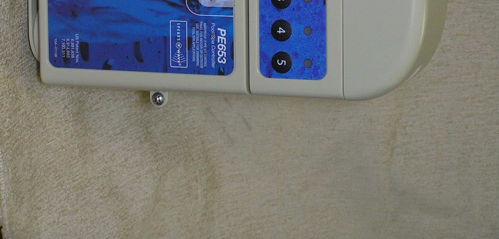
DGZPE000653
Apr 13, 20105 Circuit Digital Control
Equipment Class
DXT - Part 15 Low Power Transceiver, Rx Verified
DGZPE000953
Apr 13, 2010Hand Held Transceiver
Equipment Class
DXT - Part 15 Low Power Transceiver, Rx Verified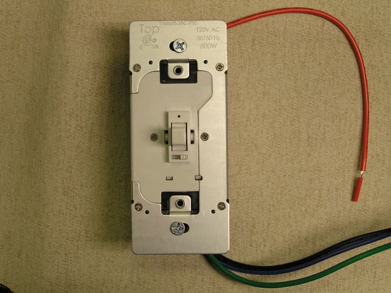
DGZHA000020P2
Mar 30, 2008In-Wall Toggle-Style Dimmer Switch
Equipment Class
DXX - Part 15 Low Power Communication Device Transmitter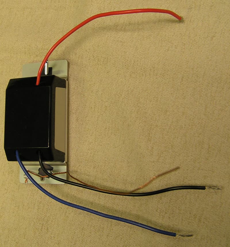
DGZHA000014P2
Mar 30, 2008In-Wall Dimmer Switch
Equipment Class
DXX - Part 15 Low Power Communication Device Transmitter