DGZH0022Remote Control
Intermatic Inc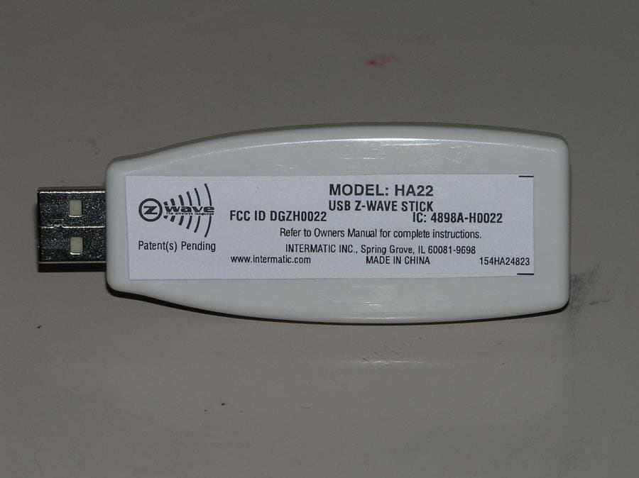
Click to zoom
Application Details
- Equipment Class
- DXT - Part 15 Low Power Transceiver, Rx Verified
- Date of Grant
- Jan 30, 2006
- Application Purpose
- Original Equipment
- Date of Application
- Jan 29, 2006
- Equipment Note
- Remote Control
- Frequency Range
- 908.42000000 - 908.42000000
- Company
- Intermatic Inc
- Country
- United States
Documents & Files
Document Text
Text extracted from the exhibit documents filed with the FCC. Open a document above to read the original.
Users Manual
Intermatic, Inc. Spring Grove, IL 60081-9698 www.intermatic.com Thank you for purchasing Intermatic’s Home Settings devices. With the HomeSettings program, you can reliably and remotely control lighting and appliances. The outstanding features of the Home Settings HA02 Appliance Module includes: • Feedback that will allow you to see whether your device has received the ON/OFF (you cannot DIM with this module) signal. • RF signal reliability – each HomeSettings product has a special feature that virtually guarantees that RF signals are received • Ease of installation • Manual override • Heavy-duty plug and receptacle • Controls compact fluorescent lights up to 42 Watts • Compatible with other Z-Wave™ enabled devices The HA02 Appliance Module is a Z-Wave™ enabled device and is fully compatible with any Home Settings network and any Z-Wave™ enabled network. Z-Wave™ enabled devices displaying the Z- Wave™ logo can also be used with Home Settings modules and controllers regardless of the manufacturer, and Home Settings modules and controllers can also be used in other manufacturer’s Z-Wave™ enabled networks. Each module in a Home Settings network is designed to act as a repeater. Repeaters will re-transmit the RF signal to ensure that the signal is received by its intended destination by routing the signal around obstacles and radio dead spots. INSTALLATION _ Enclosed you will find: 1 USB Z-Wave TM Stick 1 CD-rom containing a USB stick software driver Instruction sheets Customer response card Install USB driver. Plug USB stick into an available USB Type A Female port on your personal computer. ...Additional instructions to be inserted here... PROGRAMMING _ See the instructions for HomeSettings ThinkEssentials by Intermatic. FEDERAL COMMUNICATIONS COMMISSION STATEMENT_____________ This device complies with part 15 of the FCC rules. Operation of this device is subject to the following two conditions: (1) This device may not cause harmful interference, and (2) This device must accept any interference, including interference that may cause undesired operation. NOTE: This equipment has been tested and found to comply with the limits for a Class B digital device, pursuant to Part 15 of the FCC Rules. These limits are designed to provide reasonable protection against harmful interference in a residential installation. This equipment generates, uses and can radiate radio frequency energy and, if not installed and used in For Indoor Use Only MODEL HA22 USB Z-Wave TM Stick Intermatic, Inc. Spring Grove, IL 60081-9698 www.intermatic.com 158HAXXXXX accordance with the instructions, may cause harmful interference to radio communications. However, there is no guarantee that interference will not occur in a particular installation. If this equipment does cause harmful interference to radio or television reception, which can be determined by turning the equipment off and on, the user is encouraged to try to correct the interference by one or more of the following measures: -- Reorient or relocate the receiving antenna or device. -- Increase the separation between the equipment and receiver. -- Connect the equipment into an outlet on a circuit different from that to which the receiver is connected. -- Consult the dealer or an experienced radio/TV technician for help. WARNING! Changes or modifications not expressly approved by Intermatic Inc. could void the user’s authority to operate the equipment. The term “IC:” before the radio certification number only signifies that Industry Canada technical specifications were met. TECHNICAL INFORMATION Specificatios_ Plug: USB Type A Male USB Power Input: ~4.40 to 5.25VDC Range: >50 feet Suitable for use in dry locations Operating Temperature Range: 0°C to 40°C Made in China. _WARRANTY INFORMATION Specificios_ LIMITED 6-YEAR WARRANTY If within six (6) years from the date of purchase, this product fails due to a defect in material or workmanship, Intermatic Incorporated will repair or replace it, as its sole option, free of charge. This warranty is extended to the original household purchaser only and is not transferable. This warranty does not apply to: (a) damage to units caused by accident, dropping or abuse in handling, acts of God or any negligent use; (b) units which have been subject to unauthorized repair, opened, taken apart or otherwise modified; (c) units not used in accordance with instructions; (d) damages exceeding the cost of the product; (e) sealed lamps and/or lamp bulbs, LED’s and batteries; (f) the finish on any portion of the product, such as surface and/or weathering, as this is considered normal wear and tear; (g) transit damage, initial installation costs, removal costs, or reinstallation costs. INTERMATIC INCORPORATED WILL NOT BE LIABLE FOR INCIDENTAL OR CONSEQUENTIAL DAMAGES. SOME STATES DO NOT ALLOW THE EXCLUSION OR LIMITATION OF INCIDENTAL OR CONSEQUENTIAL DAMAGES, SO THE ABOVE LIMITATION OR EXCLUSION MAY NOT APPLY TO YOU. THIS WARRANTY IS IN LIEU OF ALL OTHER EXPRESS OR IMPLIED WARRANTIES. ALL IMPLIED WARRANTIES, INCLUDING THE WARRANTY OF MERCHANTABILITY AND THE WARRANTY OF FITNESS FOR A PARTICULAR PURPOSE, ARE HEREBY MODIFIED TO EXIST ONLY AS CONTAINED IN THIE LIMITED WARRANTY, AND SHALL BE OF THE SAME DURATION AS THE WARRANTY PERIOD STATED ABOVE. SOME STATES DO NOT ALLOW LIMITATIONS ON THE DURATIONS OF AN IMPLIED WARRANTY, SO THE ABOVE LIMITATION MAY NOT APPLY TO YOU. This warranty service is available by either (a) returning the product to the dealer from whom the unit was purchased, or (b) mailing the product, along with proof of purchase, postage prepaid to the authorized service center listed below. This warranty is made by: Intermatic Incorporated/After Sales Service/7777 Winn Rd., Spring Grove, Illinois 60081-9698/815-675-7000 http://www.intermatic.com Please be sure to wrap the product securely to avoid shipping damages.
Cover Letter(s)
FCC ID: DGZH0022 D.L.S. ELECTRONIC SYSTEMS, INC. 1250 Peterson Drive Wheeling, Illinois 60090 FCC Authorization & Evaluation Division 7435 Oakland Mills Road Columbia, Maryland 21045-0429 Gentlemen: We are submitting for Intermatic, Inc., Inc., a USB Z-Wave Stick Transmitter, Model Number: HA02, with a FCC ID: DGZH0022 for Certification. This unit has been tested and complies to Part 15, Subpart C. If there are any questions in regards to this application, please call D.L.S. Electronic Systems, Inc. at (847) 537 6400. Enclosed you will find a copy of our test report with the information and results of tests that is required under Part 15, Section 15.249. Thank you for your assistance in this matter. Sincerely, Arnom C. Rowe EMC-001375-NE DLS/sr
Cover Letter(s)
Letter of Agency Date: January 20, 2006 American Telecommunications Certification Body, Inc. 6731 Whittier Avenue Suite C110 McLean, VA 22101 To Whom It May Concern: Please be advised that Intermatic, Inc. authorizes D.L.S. Electronic Systems, Inc. to act on our behalf, until otherwise notified, for applications submitted to American Telecommunications Certification Body, Inc. (ATCB). We certify that we are not subject to denial of federal benefits, that includes FCC benefits, pursuant to Section 5301 of the Anti-Drug Abuse ACT of 1988, U.S.C. 862. Further, no party, as defined in 47 CFR 1.2002(b), to the application is subject to denial of federal benefits, that includes FCC benefits. Thank you for your attention to this matter. Signatory, Arnom C. Rowe EMC ENGINEER EMC-001375-NE D.L.S. Electronic Systems, Inc. FCC Labeling Requirements and Information Date: January 20, 2006 American Telecommunications Certification Body, Inc. 6731 Whittier Avenue Suite C110 McLean, VA 22101 RE: FCC Labeling Requirements FCC ID: DGZH0022 The following label information is required by the FCC Rules and Regulations for certified devices. Also attached, please find marketing information required by the FCC Rules and Regulations. Thank you for your attention to these matters. Sincerely, Arnom C. Rowe EMC ENGINEER EMC-001375-NE D.L.S. Electronic Systems, Inc. Modification Letter Date: January 20, 2006 American Telecommunications Certification Body, Inc. 6731 Whittier Avenue Suite C110 McLean, VA 22101 RE: Certification Application FCC ID: DGZH0022 Please be advised that the following information is a list of modifications that will be included in the production process for the above-referenced equipment. Change 1: Rerouted antenna wire from top of circuit board to bottom of circuit board. Change 2: Set power level to F0 Change 3: Change 4: Change 5: Change 6: Change 7: Change 8: Change 9 Change 10: Thank you for your attention to this matter. Signatory Arnom C. Rowe EMC ENGINEER EMC-001375-NE D.L.S. Electronic Systems, Inc. Manufacturer’s Letter Date: January 20, 2006 American Telecommunications Certification Body, Inc. 6731 Whittier Avenue Suite C110 McLean, VA 22101 RE: Certification Application FCC ID: DGZH0022 To Whom It May Concern: Please be advised that the manufacturer will ensure that the above-referenced model will be manufactured in accordance with the FCC Rules and Regulations. Thank you for your attention to this matter. Signatory Arnom C. Rowe EMC ENGINEER EMC-001375-NE D.L.S. Electronic Systems, Inc. Request for Confidentiality Date: January 20, 2006 American Telecommunications Certification Body, Inc. 6731 Whittier Avenue Suite C110 McLean, VA 22101 RE: Certification Application FCC ID: DGZH0022 Pursuant to 47 CFR Section 0.459 Intermatic, Inc. understands that requests for non disclosure and confidential treatment is being made for the following information as stated under the Code of Federal Regulations Chapter 47, Part 0.459 and behalf of APPLICANT NAME: • Block Diagram • Schematics • Parts Lists The above materials contain trade secrets, proprietary and technical information that would customarily be guarded from competitors under 47 CFR section 0.457(d)(2). Disclosure or publication of any portion of this company confidential material to other parties could cause substantial competitive harm and provide unjustified benefits for competitors. Intermatic, Inc. understands that pursuant to 47 CFR section 0.457(d)(1)(ii) disclosure of the applicant and all accompanying documentation will not be made before the date of the grant. Thank you for your attention to this matter. Signatory Arnom C. Rowe EMC ENGINEER EMC-001375-NE D.L.S. Electronic Systems, Inc.
Cover Letter(s)
Confidential, Page 1 of 2 Intermatic Radio Frequency Home Automation System Z-Wave TM -enabled Universal Serial Bus Device MODEL: HA22 DESCRIPTION: USB Z-Wave TM Stick Preliminary Product Specifications - Revision 0.1, 1/17/2006 Written by: Patrick J. Alog – Design Engineer, Intermatic Incorporated Copyright ©2006 by Intermatic Incorporated, Spring Grove, IL 60081. All rights reserved. This document contains trade secrets of Intermatic Incorporated and its affiliated partners. Any reproduction or disclosure of this document or the information contained therein without specific written authorization of Intermatic is a violation of Intermatic’s trade secrets rights and is strictly prohibited. Z-Wave TM is a registered trademark of Zensys A/S. Confidential, Page 2 of 2 0.0 Description: Intermatic has developed a new line of lighting control products based on a mesh-networking protocol called Z-Wave TM and an ASIC chip referred to as the ZW0102. Z-Wave TM is a Wireless Control Technology developed by Zensys located in Copenhagen, Denmark. This wireless system operates in the 908.42MHz public band in the United States. For more information regarding Zensys and Z-Wave TM , please visit the Zensys website at http://www.zen-sys.com The Intermatic Home Automation lighting control system consists of the following lighting control devices: • HA01 – Duplex Receptacle • HA02 – Grounded Plug-in Appliance Module • HA03 – Plug-in Dimmable Module • HA04 – Outdoor Appliance Module • HA05 – Screw-in Lamp Module • HA06 – In-Wall Dimmer Switch Module • HA07 – 12 Channel Master Controller • HA09 – 6 Channel Handy Remote Controller Each model shares a common RF-front end transceiver design that allows simple and reliable 2- way communication between devices. A Universal Serial Bus (USB) device would allow a connected personal computer to control and manage a Z-wave TM enabled home network containing a number of the above devices, with the use of software developed specifically for that network. 1.0 Agency Requirements 1.1 FCC Part 15 – Intentional Radiator 1.2 Industry Canada (IC) 1.3 EMC – IEC 1000 4.4 Electromagnetic Compatibility Electrical Fast Transient/Burst immunity test 2.0 Technical Specifications: 2.1 Operating Frequency: 908.42MHz 2.2 Operating temperature range: 0°C to 40°C. Storage temperature: -35°C to 70°C 2.3 Operating Range: 100 feet 2.4 Environmental: 10% to 95% Non-condensing relative humidity. Indoor use only. 2.5 Power supplied by USB port, 4.40V to 5.25V DC. 2.6 Electronic design of the RF module shall be based on the US Enhanced Small Form Factor Z-Wave Module, ZW0102. See attached BOM for components required. 370100431.00.02.pdf 2.7 Design shall utilize a USB to UART microcontroller with supporting components to interface the Z-wave module with a personal computer via USB input port. 2.8 Housing design shall be as small as possible and manufactured in gloss white ABS plastic subject to approval by Intermatic. 2.9 Unit shall have a power/communications indicator LED in Green. 2.10 Package shall include a USB v2.0 extension cord 6ft. in length. END
External Photos
Company: Intermatic, Inc. Model: HA22 FCC ID: DGZH0022 IC: 4898A-H0022 Date: 01-10-2006 Photo Description: Unit with cover Company: Intermatic, Inc. Model: HA22 FCC ID: DGZH0022 IC: 4898A-H0022 Date: 01-10-2006 Photo Description: Inside Covers Company: Intermatic, Inc. Model: HA22 FCC ID: DGZH0022 IC: 4898A-H0022 Date: 01-10-2006 Photo Description: FCC and Canada ID Label & Location
ID Label/Location Info
MODEL: HA22 USB Z-WAVE STICK FCC ID DGZH0022 IC: 4898A-H0022 Refer to Owners Manual for complete instructions. INTERMATIC INC., Spring Grove, IL 60081-9698 www.intermatic.com MADE IN CHINA 154HA24823 Patent(s) Pending 154HA24823.qxp 12/20/05 2:44 PM Page 1
Internal Photos
Company: Intermatic, Inc. Model: HA22 FCC ID: DGZH0022 IC: 4898A-H0022 Date: 01-10-2006 Photo Description: Main PCB top side - RF module mounted Company: Intermatic, Inc. Model: HA22 FCC ID: DGZH0022 IC: 4898A-H0022 Date: 01-10-2006 Photo Description: Main PCB bottom side - RF module mounted Company: Intermatic, Inc. Model: HA22 FCC ID: DGZH0022 IC: 4898A-H0022 Date: 01-10-20065 Photo Description: Main PCB top side - RF module not mounted Company: Intermatic, Inc. Model: HA22 FCC ID: DGZH0022 IC: 4898A-H0022 Date: 01-10-2006 Photo Description: Main PCB bottom side - RF module not mounted Company: Intermatic, Inc. Model: HA22 FCC ID: DGZH0022 IC: 4898A-H0022 Date: 01-10-2006 Photo Description: RF Module Top Side Company: Intermatic, Inc. Model: HA22 FCC ID: DGZH0022 IC: 4898A-H0022 Date: 01-10-2006 Photo Description: RF Module Bottom Side
Operational Description
Operational Descriptions: HA22 – USB Z-Wave Stick The HA22 USB Z-Wave Stick is a Z-Wave TM interface device, similar to existing Bluetooth and Wi-Fi USB interface devices. The USB Z-Wave Stick plugs into any USB port up to USB 2.0 compliant via a Type-A male USB connector. An optional USB extension cord may be used to position the USB Stick for better reception and performance. A USB controller chip, governs the processes that involve communications between the RF module and the Personal Computer (PC). 4.4V to 5.25 VDC power is supplied by the PC’s USB port, whose voltage is passed through a voltage regulator to supply a constant 3.3VDC to the Z-Wave ASIC. The Z-wave ASIC, governs the RF module functions, including the RF transmission and reception at the front-end, and the operations of the Z-wave protocol. When lit, a single green LED indicates a communications link between the USB controller chip and the RF module. The RF module PCB is a separate PCB mounted on the main PCB that houses the Z- wave ASIC, crystals, EEPROM, various supporting components, and the RF front end. This entire PCB is completely enclosed by a metal shield connected directly to circuit ground. The RF module PCB is attached directly to the main HA22 PCB via headers. The 908.42MHz antenna measuring approximately 3.25” in length, exits the metal shield via a small hole in the bottom of the shield, and passes through the main PCB through a hole located directly underneath the hole in the bottom of the RF shield. When combined with the appropriate PC software, the USB Z-Wave Stick has the ability to send commands and receive acknowledgement and other feedback to other Z-Wave enabled devices.
Test Report
Company: Intermatic Incorporated Model Tested: HA22 Report Number: 11905 1250 Peterson Dr., Wheeling, IL 60090 FCC Rules and Regulations / Intentional Radiators Operational in the 902-928 MHz, 2400-2483.5 MHz, 5725-5875 MHz, and 24.0-24.25 GHz Bands Part 15, Subpart C, Section 15.249 THE FOLLOWING ''MEETS'' THE ABOVE TEST SPECIFICATION Formal Name: USB Z-Wave Stick Kind of Equipment: USB Device Test Configuration: USB Type A (Male) connector (Tested at 120 vac, 60 Hz) Model Number(s): HA22 Model(s) Tested: HA22 Serial Number(s): N/A Date of Tests: January 6 & 9, 2006 Test Conducted For: Intermatic Incorporated 7777 Winn Road Spring Grove, Illinois 60081 NOTICE: “This report must not be used by the client to claim product endorsement by NVLAP or any agency of the U.S. Government”. Please see the "Additional Description of Equipment Under Test" page listed inside of this report. This report must not be reproduced (except in full), without the approval of D.L.S. Electronic Systems. Page - 1 - Company: Intermatic Incorporated Model Tested: HA22 Report Number: 11905 1250 Peterson Dr., Wheeling, IL 60090 SIGNATURE PAGE Report By: Arnom C. Rowe Test Engineer EMC-001375-NE Reviewed By: William Stumpf OATS Manager Approved By: Brian Mattson General Manager Company Official: Intermatic Incorporated Page - 2 - Company: Intermatic Incorporated Model Tested: HA22 Report Number: 11905 1250 Peterson Dr., Wheeling, IL 6009 TABLE OF CONTENTS i. Cover Page................................................................................................................................................1 ii. Signature Page..........................................................................................................................................2 iii. Table of Contents..................................................................................................................................3 iv. NVLAP Certificate of Accreditation....................................................................................................4 v. NVLAP Scope of Accreditation...............................................................................................................5 1.0 Summary of Test Report.....................................................................................................................13 2.0 Introduction.........................................................................................................................................13 3.0 Object..................................................................................................................................................13 4.0 Test Set-Up.........................................................................................................................................14 5.0 Test Equipment...................................................................................................................................15 6.0 Ambient Measurements......................................................................................................................16 7.0 Description of Test Sample.................................................................................................................17 8.0 Additional Description of Test Sample...............................................................................................18 9.0 Photo Information and Test Set-Up....................................................................................................19 10.0 Radiated Photos Taken During Testing..............................................................................................20 10.0 Conducted Photos Taken During Testing...........................................................................................24 11.0 Results of Tests...................................................................................................................................25 12.0 Conclusion..........................................................................................................................................25 TABLE 1 – EQUIPMENT LIST....................................................................................................................26 Appendix A – Electric Field Radiated Emissions Test...................................................................................28 1.0 Conducted Emission Measurements...................................................................................................29 1.0 Conducted Data and Graph(s) taken during testing............................................................................ 30 2.0 Band Edge and Restrict Band Compliance.........................................................................................35 2.0 Data and Graph(s) taken showing the Band Edge and Restrict Band Compliance............................36 3.0 Field Strength of Spurious Emission Measurements..........................................................................38 3.0 Radiated Data and Graph(s) taken for Fundamental Emission Measurements..................................40 3.0 Radiated Data and Graph(s) taken for Field Strength Spurious Emission Measurements.................47 Page -3- Company: Intermatic Incorporated Model Tested: HA22 Report Number: 11905 1250 Peterson Dr., Wheeling, IL 6009 Page -4- Company: Intermatic Incorporated Model Tested: HA22 Report Number: 11905 1250 Peterson Dr., Wheeling, IL 6009 Page -5- Company: Intermatic Incorporated Model Tested: HA22 Report Number: 11905 1250 Peterson Dr., Wheeling, IL 6009 Page -6- Company: Intermatic Incorporated Model Tested: HA22 Report Number: 11905 1250 Peterson Dr., Wheeling, IL 6009 Page -7- Company: Intermatic Incorporated Model Tested: HA22 Report Number: 11905 1250 Peterson Dr., Wheeling, IL 6009 Page -8- Company: Intermatic Incorporated Model Tested: HA22 Report Number: 11905 1250 Peterson Dr., Wheeling, IL 6009 Page -9- Company: Int…
Text truncated - open the document above for the full version.
Test Setup Photos
Company: Intermatic, Inc. Model: HA22 FCC ID: DGZH0022 IC: 4898A-H0022 Date: 01-10-2006 Photo Description: URadiated Test - Front Company: Intermatic, Inc. Model: HA22 FCC ID: DGZH0022 IC: 4898A-H0022 Date: 01-10-2006 Photo Description: URadiated Test – Front, close up Company: Intermatic, Inc. Model: HA22 FCC ID: DGZH0022 IC: 4898A-H0022 Date: 01-10-2006 Photo Description: URadiated Test – Front, close up Company: Intermatic, Inc. Model: HA22 FCC ID: DGZH0022 IC: 4898A-H0022 Date: 01-10-2006 Photo Description: URadiated Test – Back Company: Intermatic, Inc. Model: HA22 FCC ID: DGZH0022 IC: 4898A-H0022 Date: 01-10-2006 Photo Description: UConducted Test
Contact Information
Applicant
Kimberly Boland(Director of Engineering)
Technical Contact
DLS Electronic SystemsArnom Rowe
847-537-6400
1250 Peterson Drive · Wheeling, Illinois · United States
Test Firm
DLS Electronic Systems, Inc.William Stumpf
Technical Specifications
| # | Rule Parts | Frequency Range | Power Output |
|---|---|---|---|
| 1 | 15C | 908.42 MHz - 908.42 MHz | - |
Other Applications from Intermatic Inc
DGZALC24B
Mar 17, 2024Programmable Switches
Equipment Class
DTS - Digital Transmission System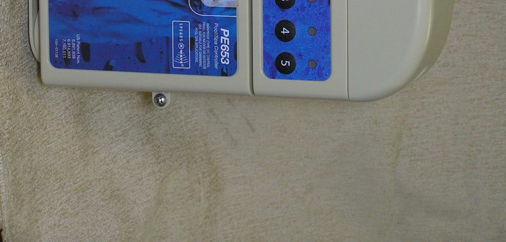
DGZPE000653
Apr 13, 20105 Circuit Digital Control
Equipment Class
DXT - Part 15 Low Power Transceiver, Rx Verified
DGZPE000953
Apr 13, 2010Hand Held Transceiver
Equipment Class
DXT - Part 15 Low Power Transceiver, Rx Verified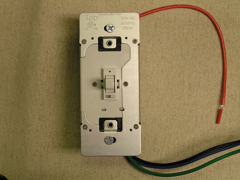
DGZHA000020P2
Mar 30, 2008In-Wall Toggle-Style Dimmer Switch
Equipment Class
DXX - Part 15 Low Power Communication Device Transmitter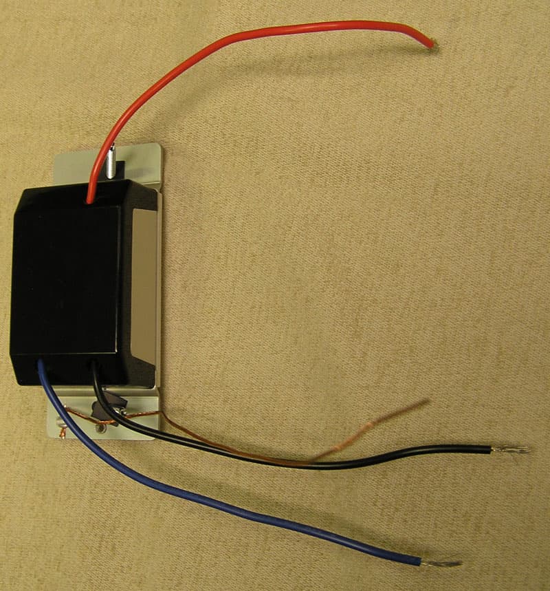
DGZHA000014P2
Mar 30, 2008In-Wall Dimmer Switch
Equipment Class
DXX - Part 15 Low Power Communication Device Transmitter