DWNDECOFLEXDECOFLEX RTS Switch
Somfy Systems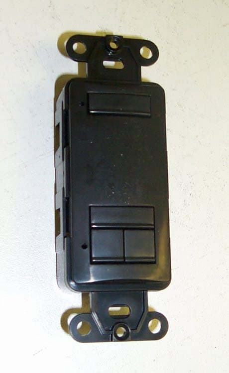
Click to zoom
Application Details
- Equipment Class
- DSC - Part 15 Security/Remote Control Transmitter
- Date of Grant
- Mar 12, 2008
- Application Purpose
- Original Equipment
- Date of Application
- Mar 12, 2008
- Equipment Note
- DECOFLEX RTS Switch
- Frequency Range
- 433.42000000 - 433.42000000
- Company
- Somfy Systems
- Country
- United States
Documents & Files
Document Text
Text extracted from the exhibit documents filed with the FCC. Open a document above to read the original.
Users Manual
2 1 - - Power: 3V lithium battery, CR 2450 type oooo - Operating temperature: +5C/41F to +40C/104F - Range: Up to 65 Ft. - Fits into standard Decora Wall Plates Commands are transmitted by radio waves at 433.42 MHz. Operating Instructions DECOFLEX RTS SWITCH DESCRIPTION PROGRAMMING The DecoFlex RTS Switch is a wireless radio transmitter compatible with all Somfy RTS Motors and externally mounted RTS receivers. This is a low voltage device which does not need to be mounted inside an electrical box. It can be mounted adjacent to an existing Decora style light switch or as a stand alone device using the specific SOMFY low voltage bracket (included). White: 1810813 Ivory: 1810814 Black: 1810830 A. ADDING A DECOFLEX RTS WALL SWITCH - INITIAL INSTALLATION IMPORTANT: for initial programming provide power only to the motor or receiver being programmed 1. Set the RTS Receiver or Motor into its Programming Mode (Refer to the installation instructions of the relevant RTS receiver or motor for this procedure). 2. Select the Channel to be memorized by pressing the appropriate button. The button will light. Refer to Figure 1. 3. Using a paperclip or similar device, briefly press the programming button (1 sec max) located on the DecoFlex Switch 4. The receiver/motor will confirm the addition of the new DecoFlex Switch in their respective manners. FIGURE 1 C. REMOVING A DECOFLEX RTS SWITCH FROM THE MOTOR OR RECEIVER’S MEMORY 1. Place the receiver or motor into programming mode by pressing and holding the programming button (for 3 sec.) of a DecoFlex RTS Switch or Telis Transmitter that has been previously memorized. It should NOT be the one to be removed from memory. 2. The receiver/motor will confirm PROGRAMMING MODE in their respective manners. 3. Select the RTS Switch or Channel to be removed from memory. Press the programming button (1 sec. max.) on the RTS switch. 4. The receiver/motor will confirm the removal of the RTS Switch or Channel in their respective manners. Ref. No. 2501819 SOMFY SYSTEMS, INC. 3/08 C SOMFY SYSTEMS, INC. 47 Commerce Drive Cranbury, NJ 08512 SOMFY CANADA 6315 Shawson Drive, Unit #1 Mississauga, Ontario L5T1J2 SOMFY SYSTEMS, INC. reserves the right to change, update or improve this document without prior notice. B. ADDING MULTIPLE DECOFLEX WALL SWITCHES 1. Place the receiver or motor into programming mode by pressing and holding the programming button (for 3 sec.) of a DecoFlex switch or Telis Transmitter that has been previously memorized. There is no need to access the external receiver for this operation. 2. The receiver/motor will confirm PROGRAMMING MODE in their respective manners. 3. Select the NEW channel or RTS Switch to be memorized. Press the programming button (1 sec. max.) on the DecoFlex RTS switch. 4. The receiver/motor will confirm the addition of the new RTS Switch or Channel in their respective manners. Programming Button Select the Channel 3 OPERATION 1. Select the channel of the window treatment to be operated by pressing the appropriate button. The button will light. Refer to Figure 2. 2. To raise the window treatment, press the UP button. Similarly, to lower the window treatment, press the DOWN button. 3. To stop the window treatment at any time, simply press the STOP button. FIGURE 2 Select the Channel STOP Button UP Button DOWN Button BATTERY LIFE The DecoFlex RTS Switches are powered by a 3V battery (type 2450) which provides about 25 years operation assuming 4 operations per day. When the battery becomes discharged, the control LED no longer lights up when a command is sent, and the command is not carried out. HOW TO REPLACE THE BATTERY 1. Remove the screws on the back cover of the RTS Switch. 2. Slide the battery out of its holder by pushing it with a screwdriver. 3. Insert the new battery, maintaining its correct polarity. NOTE: Do not throw the battery in the trash, but dispose of it properly. INSTALLATION PROCEDURE MOUNTING METHOD 1. Orient the brackets flat side against the wall keeping the thin side closest to and centered with the existing electrical switch box. drywall 6. Mount low voltage switch into bracket, with its edge flush against electrical switch box. 7. Finish the installation by mounting a standard double gang Decora switch cover plate, over both switches. 5. To keep the bracket in o place, bend tabs 90around drywall, as tightly as possible. 4. Insert bracket (as shown) into hole, keeping the thin side closest to the existing switch box, and laying flat on drywall. 2. Align the inside edge of the thin side of the bracket with the outside edge of the switch box. Then trace the inside shape (as shown by the dashed line in the diagram) of the bracket. (sheetrock not shown for clarity) 3. Cut traced opening into drywall. Be careful not to make the opening larger than necessary, to ensure a tight fit. Use dimensions in diagram below. Do not exceed these dimensions to ensure a proper fit of the bracket thin side of bracket 7 3 / 16 7 3 / 16 5 1 / 8 5 1 / 8 1.30 Inside Edge Existing Electrical Box w o o d 2 x 4 NOTE: This bracket is designed for an existing electrical box already behind the sheetrock. If a retrofit electrical box was used, it is recommended to remove the single gang and replace it with a double gang retrofit box. The special SOMFY low voltage bracket is specifically designed to mount the DecoFlex RTS wall switch next to an existing Decora light switch with an electrical box already behind the drywall. This bracket differs from other off-the-shelf low voltage brackets because it is offset on one side. This allows a double gang Decora style cover plate to fit over both switches without installing a double gang electrical box behind the drywall. It is also possible to mount this bracket as a stand alone low voltage device. 4 5 2 . 6 1 This device complies with part 15 of the FCC Rules. Operation is subject to the following two conditions: (i). This device may not cause harmful interference, and (ii). This device must accept…
Text truncated - open the document above for the full version.
Cover Letter(s)
November 16, 2007 Compliance Certification Services Certification Division 561F Monterey Road Morgan Hill, CA 95037 To whom it may concern: We, the undersigned, hereby authorize Advanced Compliance Lab, to act on our behalf in all manners relating to application for equipment authorization, including signing of all documents relating to these matters. Any and all acts carried out by Advanced Compliance Lab on our behalf shall have the same effect as acts of our own. We, the undersigned, hereby certify that we are not subject to a denial of federal benefits, that includes FCC benefits, pursuant to Section 5301 of the Anti-Drug Abuse Act of 1988, 21 U.S.C. 853(a). In authorizing Advanced Compliance as our agent, we still recognize that we are responsible to: a) comply with the relevant provisions of the certification program; b) make all necessary arrangements for the conduct of the evaluation, including provision for examining documentation and access to all areas, records (including internal audit reports) and personnel for the purposes of evaluation (e.g. testing, inspection, assessment, surveillance, reassessment) and resolution of complaints; c) make claims regarding certification only in respect of the scope for which certification has been granted; d) do not use our product certification in such a manner as to bring the Certification Division into disrepute and not make any statement regarding our product certification which the Certification Division may consider misleading or unauthorized; e) upon suspension or cancellation of certification, discontinue use of all advertising matter that contains any reference thereto and return any certification documents as required by the Certification Division; f) use certification only to indicate the products are certified as being in conformity with specified standards; g) endeavor to ensure that no certificate or report nor any part thereof is used in a misleading manner; h) ensure that any reference to our product certification in communication media such as documents, brochures or advertising, complies with the requirements of the Certification Division; i) keep a record of all complaints made known to the us relating to the product’s compliance with requirements of the relevant standard and to make these records available to the Certification Division when requested; j) take appropriate action with respect to such complaints and any deficiencies found in products or services that affect compliance with the requirements for certification; k) document the actions taken. This authorization is valid until further written notice from the applicant. Sincerely Yours, Jim Hellander Industrial Operations Mgr. Somfy Systems, Inc.
Cover Letter(s)
March 3, 2008 FCC and IC Confidentiality Request In accordance with 0.459 & 0.457 of CFR 47, please, accept this letter as an official request to have the schematics, block diagram of the EUT treated as confidential. The information contained within is a result of extensive investment and development effort by Somfy Systems, Inc. and its disclosure will compromise Somfy’s Intellectual Property and competitive edge. We thus ask the FCC and IC NOT to publish the information mentioned above, in order to protect Somfy’s Intellectual Property. Regards, Jim Hellander Somfy Systems, Inc. Jim Hellander Industrial Operations Mgr.
External Photos
FCC ID: DWNDECOFLEX ——————————————————————————————————————————————— Advanced Compliance Lab, 6 Randolph Way, Hillsborough, NJ 08844 Tel: (908) 927-9288 Fax: (908) 927-0728 23 Figure 7.1 Front View FCC ID: DWNDECOFLEX ——————————————————————————————————————————————— Advanced Compliance Lab, 6 Randolph Way, Hillsborough, NJ 08844 Tel: (908) 927-9288 Fax: (908) 927-0728 24 Figure 7.2 Rear View
External Photos
DecoFlex external photo with platic cover FCC ID: DWNDECOFLEX
ID Label/Location Info
FCC ID: DWNDECOFLEX ——————————————————————————————————————————————— Advanced Compliance Lab, 6 Randolph Way, Hillsborough, NJ 08844 Tel: (908) 927-9288 Fax: (908) 927-0728 8 2. PRODUCT LABELING Figure 2.1 FCC ID Label Figure 2.2 Location of Label on the Side of EUT Figure 2.2 FCC ID Label Location FCC ID: DWNDECOFLEX This device complies with part 15 of the FCC Rules. Operating is subject to the following two conditions: (1) This device may not cause harmful interference, and (2) this device must accept any interference received, including interference that may cause undesired operation. Figure 2.1 FCC ID Label ( statement in the manual) FCC Label
Internal Photos
FCC ID: DWNDECOFLEX ——————————————————————————————————————————————— Advanced Compliance Lab, 6 Randolph Way, Hillsborough, NJ 08844 Tel: (908) 927-9288 Fax: (908) 927-0728 25 Figure 7.3 Component FCC ID: DWNDECOFLEX ——————————————————————————————————————————————— Advanced Compliance Lab, 6 Randolph Way, Hillsborough, NJ 08844 Tel: (908) 927-9288 Fax: (908) 927-0728 26 Figure 7.4 Foil Side
Operational Description
Somfy DecoFlex Switch (#1810813, 1810814, 1810830) Operational Description Power Supply Battery powered device. Additional electronics resets micro when battery is discharged. Clock Generator Generates the 433.42 MHz clock for the transmitter amplifier. Modulator, Transmitter Amplifier Modulates the carrier with a digital signal from the microcontroller for data transmission. The transmitter amplifier amplifies the modulated carrier. Microcontroller Processes the input signals from the push-button switches and “decides” which RF signal to send.
Parts List/Tune Up Info
BILL OF MATERIALS - SOMFY NEW DECORA 3/8/2008 ITEM DESCRIPTION MANUFACTURER PART NUMBER B1 BATTERY HOLDER FOR 2450 BATTERY KEYSTONE 3008 BATT BATTERY SANYO CR2450 C2 CERAMIC CHIP CAPACITOR 0603 10% 0.1UF MURATA GRM188R71H104KA93D C5 CERAMIC CHIP CAPACITOR 0603 +/-0.1P 1 P MURATA GRM1885C1H1R0BZ01D C6 CERAMIC CHIP CAPACITOR 0603 +/-5% 12 P MURATA GRM1885C1H120JA01D C7 CERAMIC CHIP CAPACITOR 0603 +/-0.5P 5.6 P MURATA GRM1885C1H5R6DZ01D C8 CERAMIC CHIP CAPACITOR 0603 10% 1000P MURATA GRM188R71H102KA01D C9 CERAMIC CHIP CAPACITOR 0603 +/-0.25P 2.2 P MURATA GRM1885C1H2R2CZ01D C10 CERAMIC CHIP CAPACITOR 0603 10% 1000P MURATA GRM188R71H102KA01D C11 CERAMIC CHIP CAPACITOR 0603 10% 1000P MURATA GRM188R71H102KA01D C12 CERAMIC CHIP CAPACITOR 0603 5% 100 P MURATA GRM1885C1H101JA01D D2 DUAL DIODE COMMON ANODE SOT323 N XP BAT54AW D3 DUAL DIODE COMMON ANODE SOT323 N XP BAT54AW D4 DUAL DIODE COMMON ANODE SOT323 N XP BAT54AW D5 DUAL DIODE COMMON ANODE SOT323 N XP BAT54AW IC1 MICROCONTROLLER MICROCHIP PIC16F882I/SS IC2 RESET CIRCUIT MICROCHIP MCP103T-195I/TT J1 PROGRAMMING CONNECTOR SAMTEC CLP-103-2-G-D L1 CHIP INDUCTOR 0603 5% 15 NH PANASONIC ELJ-RE15NJF2 L2 CHIP INDUCTOR 0603 5% 15 NH PANASONIC ELJ-RE15NJF2 L3 CHIP INDUCTOR 0603 5% 33 NH PANASONIC ELJ-RE33NJF2 LED1 SMD YELLOW LED 0603 LITEON LTST-C190KSKT LED2 SMD YELLOW LED 0603 LITEON LTST-C190KSKT LED3 SMD YELLOW LED 0603 LITEON LTST-C190KSKT LED4 SMD YELLOW LED 0603 LITEON LTST-C190KSKT LED5 SMD YELLOW LED 0603 LITEON LTST-C190KSKT PCB PRINTED CIRCUIT BOARD FR4 0.031 TBD Q2 RF TRANSISTOR VISHEY BFQ67 1 BILL OF MATERIALS - SOMFY NEW DECORA 3/8/2008 Q3 RF TRANSISTOR VISHEY BFQ67 R1 CHIP RESISTOR 0603 5% 470 DALE CRCW-0603-471JT1 R2 QUAD RESISTOR 470 5% PANASONIC EXB-38V471JV R3 CHIP RESISTOR 0603 5% 10K DALE CRCW-0603-103JT1 R4 QUAD RESISTOR 10K 5% PANASONIC EXB-38V103JV R5 DAUL RESISTOR 10K 5% PANASONIC EXB-34V103JV R6 DAUL RESISTOR 10K 5% PANASONIC EXB-34V103JV R7 CHIP RESISTOR 0603 5% 10K DALE CRCW-0603-103JT1 R8 CHIP RESISTOR 0603 5% 10K DALE CRCW-0603-103JT1 R16 CHIP RESISTOR 0603 5% 10K DALE CRCW-0603-103JT1 S1 SWTICH SMD OMRON B3FS-1002P S2 SWTICH SMD OMRON B3FS-1002P S3 SWTICH SMD OMRON B3FS-1002P S4 SWTICH SMD OMRON B3FS-1002P S5 SWTICH SMD OMRON B3FS-1002P S6 SWTICH SMD OMRON B3FS-1002P S7 SWTICH SMD OMRON B3FS-1002P S8 SWTICH SMD OMRON B3FS-1002P S9 SWITCH SMD FOR PROGRAMMING TYCO/ ALCOSWITCH FSMSM X1 SAW RESONATOR RFM RO2112A X2 NOT USED NOTE- INDUCTORS, CAPACITORS AND SEMIS CANNOT BE SUBSTITUTED 2
Test Report
ELECTROMAGNETIC EMISSION COMPLIANCE REPORT of RTS SWITCH MODEL: DECOFLEX FCC ID: DWNDECOFLEX March 6, 2008 This report concerns (check one): Original grant x Class II change Equipment type: Low Power Intentional Radiator Deferred grant requested per 47 CF 0.457(d)(1)(ii)? yes no x If yes, defer until: (date) Company agrees to notify the Commission by (date) of the intended date of announcement of the product so that the grant can be issued on that date. Transition Rules Request per 15.37? yes no x If no, assumed Part 15, Subpart B for unintentional radiators - the new 47 CFR [10-1-90 Edition] provision. Report prepared for: Somfy System, Inc. Report prepared by: Advanced Compliance Lab Report number: 0048-080214-01 The test result in this report IS supported and covered by the NVLAP accreditation 6 Randolph Way Hillsborough, NJ 08844 Tel: (908) 927 9288 Fax: (908) 927 0728 Advanced Compliance Laboratory FCC ID: DWNDECOFLEX ——————————————————————————————————————————————— Advanced Compliance Lab, 6 Randolph Way, Hillsborough, NJ 08844 Tel: (908) 927-9288 Fax: (908) 927-0728 2 Table of Contents Report Cover Page .........................................................................................................1 Table of Contents ...........................................................................................................2 Figures.............................................................................................................................3 1. GENERAL INFORMATION ...................................................................................4 1.1 Verification of Compliance .........................................................................4 1.2 Equipment Modifications............................................................................5 1.3 Product Information....................................................................................6 1.4 Test Methodology.........................................................................................6 1.5 Test Facility ..................................................................................................6 1.6 Test Equipment ............................................................................................6 1.7 Statement of the Document Use..................................................................7 2. PRODUCT LABELING............................................................................................8 3. SYSTEM TEST CONFIGURATION ......................................................................9 3.1 Justification ..................................................................................................9 3.2 Special Accessories.......................................................................................9 3.3 Configuration of Tested System .................................................................9 4. SYSTEM SCHEMATICS .........................................................................................13 5. CONDUCTED EMISSION DATA ..........................................................................14 5.1 Test Methods and Conditions .....................................................................14 5.2 Test Data .......................................................................................................14 6. RADIATED EMISSION DATA ...............................................................................17 6.1 Field Strength Calculation ..........................................................................17 6.2 Test Methods and Conditions .....................................................................17 6.2 Test Data .......................................................................................................17 6.4. Occupied Bandwidth ..................................................................................19 7. PHOTOS OF TESTED EUT ....................................................................................22 FCC ID: DWNDECOFLEX ——————————————————————————————————————————————— Advanced Compliance Lab, 6 Randolph Way, Hillsborough, NJ 08844 Tel: (908) 927-9288 Fax: (908) 927-0728 3 Figures Figure 2.1 FCC ID Label...............................................................................................8 Figure 2.2 Location of Label on Back of the EUT ......................................................8 Figure 3.1 Radiated Test Setup, Position 1..................................................................10 Figure 3.2 Radiated Test Setup, Position 2..................................................................10 Figure 3.3 Radiated Test Setup, Position 3..................................................................11 Figure 3.4 Conducted Test Setup, Front......................................................................12 Figure 3.5 Conducted Test Setup, Rear .......................................................................12 Figure 4.1 EUT Schematics ...........................................................................................13 Figure 5.1 Line Conducted............................................................................................15 Figure 5.2 Neutral Conducted .....................................................................................16 Figure 6.1 Bandwidth Plot ............................................................................................19 Figure 6.2 Pulse Train Timing......................................................................................20 Figure 7.1 Front View....................................................................................................23 Figure 7.2 Rear View .....................................................................................................24 Figure 7.3 Component Side ...........................................................................................25 Figure 7.4 Foil Side .......................................…
Text truncated - open the document above for the full version.
Test Setup Photos
FCC ID: DWNDECOFLEX ——————————————————————————————————————————————— Advanced Compliance Lab, 6 Randolph Way, Hillsborough, NJ 08844 Tel: (908) 927-9288 Fax: (908) 927-0728 11 Figure 3.3 Radiated Test Setup, position 3-Z
Contact Information
Applicant
James P Hellander(Industrial Operations Manager)
Test Firm
Advanced Compliance LaboratoryWei Li
Technical Specifications
| # | Rule Parts | Frequency Range | Power Output |
|---|---|---|---|
| 1 | 15.231 | 433.42 MHz - 433.42 MHz | - |
Other Applications from Somfy Systems
DWNV2TDBUBL
Aug 19, 2026Ysia 1, Ysia 5, Ysia 5 TDBU HP Zigbee II, 5175210B, 5175211B, 5175066B
Equipment Class
DTS - Digital Transmission System
DWNVARBL
Aug 18, 2026Ysia 5 Variation HP Zigbee II, 5171079B
Equipment Class
DTS - Digital Transmission System
DWNTDBU25ZB
Jun 23, 2026TDBU 25 WF Zigbee HP 5183668
Equipment Class
DTS - Digital Transmission System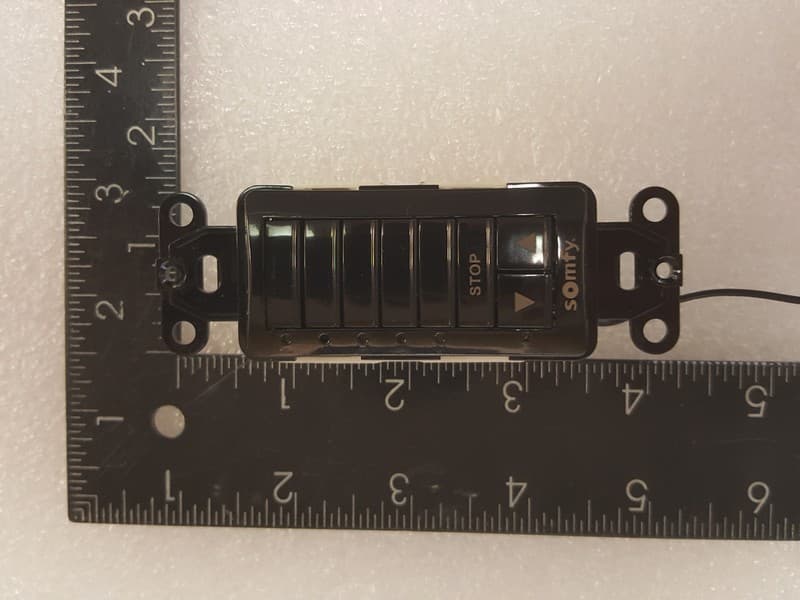
DWNDECOFLEX2
Feb 25, 2026Decoflex RTS In-Wall Mount 1810830
Equipment Class
DSC - Part 15 Security/Remote Control Transmitter
DWN-ROLLUPZB24
Sep 23, 2025ROLL UP2 24 Zigbee HP LI-ON 5178669
Equipment Class
DTS - Digital Transmission System