DWNEWF3DEolis WireFree 3D Remote Controller
Somfy Systems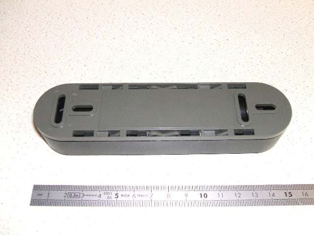
Click to zoom
Application Details
- Equipment Class
- DSC - Part 15 Security/Remote Control Transmitter
- Date of Grant
- Oct 29, 2007
- Application Purpose
- Original Equipment
- Date of Application
- Oct 29, 2007
- Equipment Note
- Eolis WireFree 3D Remote Controller
- Frequency Range
- 433.42000000 - 433.42000000
- Company
- Somfy Systems
- Country
- United States
Documents & Files
Document Text
Text extracted from the exhibit documents filed with the FCC. Open a document above to read the original.
Users Manual
Installationsanleitung Der Eolis 3D WireFree RTS ist ein drahtlo- ser, autonomer Schwingungssensor. Er misst die an der Markise bei Wind auftretenden Schwingungen in 3 Dimensionen und sendet bei Überschreiten des eingestellten Schwellenwertes ein „Wind“-Signal an einen Funkempfänger. Die Gelenkarmmarkise wird dann durch den Antrieb eingefahren. Der Eolis 3D Wirefree RTS ist ausschließlich für offene, halbgeschlossene und vollgeschlossene Markisen mit Gelenkarmen bestimmt und kompatibel zu allen Somfy RTS-Empfängern, die Windsignale verarbeiten können. Der Eolis 3D Wirefree RTS ist mit die aktuellen RTS-Antrieben, RTS-Fernbedienungen und RTS-Sensoren von Somfy kompatibel. Die Markise kann nicht vor plötzlichen Windböen geschützt werden. Im Falle solcher witterungsbe- dingter Risiken müssen Sie sicherstellen, dass die Markise geschlossen bleibt. 1. Sicherheit Dieses Somfy-Produkt muss von einer fachlich quali- fizierten Person installiert werden, für den diese Anleitung bestimmt ist. Vor der Montage muss die Kompatibilität dieses Produkts mit den dazugehörigen Ausrüstungs- und Zubehörteilen geprüft werden. Diese Anleitung beschreibt die Installation, die Inbetriebnahme und die Bedienung dieses Produkts. Die fachlich qualifizierte Person muss außerdem alle im Installationsland geltenden Normen und Gesetze befolgen, und seine Kunden über die Bedienungs- und Wartungsbedingungen des Produkts informieren. Jede Verwendung, die nicht dem von Somfy bestim- mten Anwendungsbereich entspricht, gilt als nicht bestimmungsgemäß. Im Falle einer nicht bestim- mungsgemäßen Verwendung, wie auch bei Nicht- Befolgung der Hinweise in dieser Anleitung, verfällt die Verantwortung und die Gewährleistungspflicht von Somfy. 2. Einstellmodi 2.1 Einstellung durch das Auswählen eines „vorgegebenen Schwellenwertes“ Diese Einstellung entspricht einer Bewertung der Schwingungen anhand eines mit einem Potentiometer vorgegebenen Schwellenwertes. Schwellenwert 1 = hohe Empfindlichkeit gegen Schwingungen; schon schwache Schwingungen führen zum Einfahren der Markise. Schwellenwert 9 = niedrige Empfindlichkeit gegen Schwingungen; erst schwere Schwingungen führen • • zum Einfahren der Markise. Der Schwellenwert 2 bietet eine Empfindlichkeit, die auf allgemeine Erfahrungen beruht. Werksseitig wird der Eolis 3D auf den Schwellenwert 2 eingestellt. 2.2 Einstellung durch Vorgabe einer „manuellen Schwingung“ Diese Einstellung erfasst Schwingungen, die an der ausgefahrenen Markise von Hand vorgegeben werden. Die Intensität der manuell hervorgerufenen Schwingungen wird vom Sensor gemessen und gespeichert. Werden keine manuellen Schwingungen vorgegeben, schaltet der Eolis 3 D WireFree RTS automatisch auf den Schwellenwert 2. Nach Einstellen eines Schwellenwertes schaltet der Sensor für die ersten zwei Zyklen in den Demo- Modus um. In diesem Modus kann die Markise gestoppt und sofort wieder ausgefahren werden. Die Empfindlichkeit kann neu eingestellt werden. Nach diesen zwei Zyklen schaltet der Sensor automa- tisch in den Normalbetrieb. 3. Beschreibung der Komponen- ten 1. Gehäusedeckel 2. Sensor 3. Halterung 4. Potentiometer 5. PROG-Taste 6. Alkali-Batterien AAA Siehe Abbildung A 4. Montage 4.1 Montagehinweise Montieren Sie die Halterung des Eolis 3D an den Enden oder in der Mitte des Ausfallprofils. Für die bestmögli- che Erfassung der Schwingungen empfehlen wir eine Montage an den Enden des Ausfallprofils. Achtung! Der Eolis 3D darf nie in den Hohlraum des Ausfallprofils eingeschlossen werden! Achtung! Der Eolis 3D ist erst aktiv, wenn der Sensor (2) in der Halterung (3) eingeschoben und die Einstellung abgeschlossen ist. Achtung! Die Reichweite des Sensors beträgt X = 20 m. Die Funktion des Sensors kann durch leistungsstarke lokale Sendegeräte (z.B. schnurlose Kopfhörer), die auf der gleichen Frequenz senden, beeinträchtigt werden. Siehe Abbildung B 4.2 Vormontage der Halterung Achtung! Kombinieren Sie nie verschiedene Befesti- gungssysteme miteinander. 4.2.1 Befestigung der Halterung mittels Klebeband Achtung! Das mitgelieferte doppelseitige Klebeband ► ► ist nur für eine einmalige Verwendung bestimmt. Nur das von Somfy mitgelieferte Klebeband verwenden. Die Verwendung von anderen Klebebändern ist untersagt! Wählen Sie eine geeignete Stelle am Ausfallprofil. Vergewissern Sie sich, dass bei vollständig geschlossener Markise genügend Platz für den Eolis 3D vorhanden ist. Das Schließen der Markise darf nicht behindert und der Sensor beim Einfahren nicht beschädigt werden. Reinigen Sie diese Stelle des Ausfallprofils. Tragen Sie das Klebeband auf die Rückseite der Halterung (3) auf. Befestigen Sie die Halterung samt Klebeband am Ausfallprofil: Der Pfeil (7) auf der Halterung muss nach oben zeigen. Siehe Abbildung C 4.2.2 Weitere Befestigungsmöglichkeiten für die Halterung Die Halterung (3) kann ohne Unterlegscheiben mit Hilfe von 2 passenden Zylinderkopfschrauben ø 4 mm, 2 passenden Linsenkopfschrauben ø 4 mm, 2 passenden Blindnieten oder weiterem Zubehör von Somfy befestigt werden (diese Befestigungsmittel sind nicht im Lieferumfang enthalten). Wählen Sie eine geeignete Stelle am Ausfallprofil. Vergewissern Sie sich, dass bei vollständig geschlossener Markise genügend Platz für den Eolis 3D vorhanden ist. Das Schließen der Markise darf nicht behindert und der Sensor beim Einfahren nicht beschädigt werden. Bohren Sie bei Befestigung mittels Schrauben zwei Löcher in das Ausfallprofil. Der Abstand der beiden Bohrlöcher muss dem Mittelabstand der Befestigungsbohrungen an der Halterung entspre- chen (siehe technische Daten – Abbildung F). Befestigen Sie die Halterung am Ausfallprofil: Der Pfeil auf der Halterung muss nach oben zeigen Siehe Abbildungen D und F 4.3 Einlegen der Batterien Achtung! Keine wiederaufladbaren Akkus zum Betrieb des Eolis 3D verwenden! Entfernen Sie den Sensor (2) mittels eines Schlitzschraubendrehers aus dem Gehäusedeckel (1). Legen Sie die mitgelieferten Batterien (6) entspre- chend der angegebenen Polarität in de…
Text truncated - open the document above for the full version.
Cover Letter(s)
October 12, 2007 Compliance Certification Services Certification Division 561F Monterey Road Morgan Hill, CA 95037 To whom it may concern: We, the undersigned, hereby authorize Advanced Compliance Lab, to act on our behalf in all manners relating to application for equipment authorization, including signing of all documents relating to these matters. Any and all acts carried out by Advanced Compliance Lab on our behalf shall have the same effect as acts of our own. We, the undersigned, hereby certify that we are not subject to a denial of federal benefits, that includes FCC benefits, pursuant to Section 5301 of the Anti-Drug Abuse Act of 1988, 21 U.S.C. 853(a). In authorizing Advanced Compliance as our agent, we still recognize that we are responsible to: a) comply with the relevant provisions of the certification program; b) make all necessary arrangements for the conduct of the evaluation, including provision for examining documentation and access to all areas, records (including internal audit reports) and personnel for the purposes of evaluation (e.g. testing, inspection, assessment, surveillance, reassessment) and resolution of complaints; c) make claims regarding certification only in respect of the scope for which certification has been granted; d) do not use our product certification in such a manner as to bring the Certification Division into disrepute and not make any statement regarding our product certification which the Certification Division may consider misleading or unauthorized; e) upon suspension or cancellation of certification, discontinue use of all advertising matter that contains any reference thereto and return any certification documents as required by the Certification Division; f) use certification only to indicate the products are certified as being in conformity with specified standards; g) endeavor to ensure that no certificate or report nor any part thereof is used in a misleading manner; h) ensure that any reference to our product certification in communication media such as documents, brochures or advertising, complies with the requirements of the Certification Division; i) keep a record of all complaints made known to the us relating to the product’s compliance with requirements of the relevant standard and to make these records available to the Certification Division when requested; j) take appropriate action with respect to such complaints and any deficiencies found in products or services that affect compliance with the requirements for certification; k) document the actions taken. This authorization is valid until further written notice from the applicant. Sincerely Yours, Jim Hellander Industrial Operations Mgr. Somfy Systems, Inc.
Cover Letter(s)
FCC ID: DWNEWF3D October 12, 2007 FCC and IC Confidentiality Request In accordance with 0.459 & 0.457 of CFR 47, please, accept this letter as an official request to have the schematics, block diagram of the EUT treated as confidential. The information contained within is a result of extensive investment and development effort by Somfy Systems, Inc. and its disclosure will compromise Somfy’s Intellectual Property and competitive edge. We thus ask the FCC and IC NOT to publish the information mentioned above, in order to protect Somfy’s Intellectual Property. Regards, Jim Hellander Somfy Systems, Inc. Jim Hellander Industrial Operations Mgr.
Cover Letter(s)
From: W Li <[email protected]> Date: October 29, 2007 4:28:05 PM PDT To: [email protected] Subject: Re: Somfy Systems,Inc., FCC ID: DWNEWF3D, Assessment NO.: AN07T7267, Notice#1 Hi, Tom. Finally I got the correct info on pulse train plot ( mixed up with others) and revised the report. Also send you the revised manual. I think these will be the last thing for approval. Thanks again for your patient. Wei [email protected] wrote: Dear Wei Li, I have reviewed the referenced application and have the following questions: 1. Please submit a signed authorization letter from the applicant naming you or your company as their agent. The date on the letter must be less than one year old. 2. Please submit a transmitter output spectrum analyzer plot showing the entire 139 msec burst, and include markers to show the beginning and end points of the 100 msec period during which the field strength is at its maximum value. If necessary please re-calculate and submit the total ON time, duty cycle, and field strength values. 3. There was no letter requesting confidentiality for block diagram, schematic diagram and theory of operation. If you want these exhibits to be kept from public inspection, please submit a confidentiality request letter per 0.457 and 0.459 of the Rules, otherwise these exhibits will be available for public inspection on the FCC website 4. Please provide a modified user manual with the information required by section 15.21 of the Rules The items indicated above must be submitted before processing can continue on the above referenced application. Failure to provide the requested information within 30 days of the original e-mail date may result in application dismissal and forfeiture of the filing fee. Also, please note that partial responses increase processing time and should not be submitted. Any questions about the content of this correspondence should be directed to the e-mail address listed below the name of the sender. From: W Li <[email protected]> Date: October 16, 2007 1:08:46 PM PDT To: [email protected] Subject: Re: Somfy Systems,Inc., FCC ID: DWNEWF3D, Assessment NO.: AN07T7267, Notice#1 Thanks a lot ! The letters were uploaded to the site already. I attach them again here. Regards, Wei [email protected] wrote: Dear Wei Li, I have reviewed the referenced application and have the following questions: 1. Please submit a signed authorization letter from the applicant naming you or your company as their agent. The date on the letter must be less than one year old. 2. Please submit a transmitter output spectrum analyzer plot showing the entire 139 msec burst, and include markers to show the beginning and end points of the 100 msec period during which the field strength is at its maximum value. If necessary please re-calculate and submit the total ON time, duty cycle, and field strength values. 3. There was no letter requesting confidentiality for block diagram, schematic diagram and theory of operation. If you want these exhibits to be kept from public inspection, please submit a confidentiality request letter per 0.457 and 0.459 of the Rules, otherwise these exhibits will be available for public inspection on the FCC website 4. Please provide a modified user manual with the information required by section 15.21 of the Rules The items indicated above must be submitted before processing can continue on the above referenced application. Failure to provide the requested information within 30 days of the original e-mail date may result in application dismissal and forfeiture of the filing fee. Also, please note that partial responses increase processing time and should not be submitted. Any questions about the content of this correspondence should be directed to the e-mail address listed below the name of the sender.
External Photos
FCC ID : DWNEWF3D 2. External photos
ID Label/Location Info
FCC ID: DWNEWF3D 8 2. PRODUCT LABELING Figure 2.1 FCC ID Label Figure 2.2 Location of Label on the Side of EUT Figure 2.2 FCC ID Label Location FCC ID: DWNEWF3D This device complies with part 15 of the FCC Rules. Operating is subject to the following two conditions: (1) This device may not cause harmful interference, and (2) this device must accept any interference received, including interference that may cause undesired operation. Figure 2.1 FCC ID Label (FCC statement will be shown in the user manual)
Internal Photos
FCC ID : DWNEWF3D 3. Internal photos FCC ID : DWNEWF3D
Operational Description
FCC ID : DWNEWF3D 5. Operational description The Eolis 3D wirefree RTS is a movement sensor bound to be fixed on the load bar of a RF- controlled motorized awning. When it detects any excessive vibrations of the awning due to the wind, it sends to the awning motor a RF frame in order to make it get in. The sensitivity of the device may be adjusted by a 10-position rotary switch A pushbutton and a led are needed for the pairing of the device to the awning motor. The RF frame is modulated (AM) to 433.42 signal by the transmitter, and amplified before the antenna. Power supply : 2 AAA batteries supply the system
Test Report
FCC ID: DWNEWF3D 1 ELECTROMAGNETIC EMISSION COMPLIANCE REPORT of EOLIS MODEL: WIREFREE 3D FCC ID: DWNEWF3D October 9, 2007 This report concerns (check one): Original grant x Class II change Equipment type: Low Power Intentional Radiator Deferred grant requested per 47 CF 0.457(d)(1)(ii)? yes no x If yes, defer until: (date) Company agrees to notify the Commission by (date) of the intended date of announcement of the product so that the grant can be issued on that date. Transition Rules Request per 15.37? yes no x If no, assumed Part 15, Subpart B for unintentional radiators - the new 47 CFR [10-1-90 Edition] provision. Report prepared for: Somfy System, Inc. Report prepared by: Advanced Compliance Lab Report number: 0048-070925-01 The test result in this report IS supported and covered by the NVLAP accreditation 6 Randolph Way Hillsborough, NJ 08844 Tel: (908) 927 9288 Fax: (908) 927 0728 Advanced Compliance Laboratory FCC ID: DWNEWF3D 2 Table of Contents Report Cover Page .........................................................................................................1 Table of Contents ...........................................................................................................2 Figures.............................................................................................................................3 1. GENERAL INFORMATION ...................................................................................4 1.1 Verification of Compliance .........................................................................4 1.2 Equipment Modifications............................................................................5 1.3 Product Information....................................................................................6 1.4 Test Methodology.........................................................................................6 1.5 Test Facility ..................................................................................................6 1.6 Test Equipment ............................................................................................6 1.7 Statement of the Document Use..................................................................7 2. PRODUCT LABELING............................................................................................8 3. SYSTEM TEST CONFIGURATION ......................................................................9 3.1 Justification ..................................................................................................9 3.2 Special Accessories.......................................................................................9 3.3 Configuration of Tested System .................................................................9 4. SYSTEM SCHEMATICS .........................................................................................13 5. CONDUCTED EMISSION DATA ..........................................................................14 5.1 Test Methods and Conditions .....................................................................14 5.2 Test Data .......................................................................................................14 6. RADIATED EMISSION DATA ...............................................................................17 6.1 Field Strength Calculation ..........................................................................17 6.2 Test Methods and Conditions .....................................................................17 6.2 Test Data .......................................................................................................17 6.4. Occupied Bandwidth ..................................................................................19 7. PHOTOS OF TESTED EUT ....................................................................................22 FCC ID: DWNEWF3D 3 Figures Figure 2.1 FCC ID Label...............................................................................................8 Figure 2.2 Location of Label on Back of the EUT ......................................................8 Figure 3.1 Radiated Test Setup, Position 1..................................................................10 Figure 3.2 Radiated Test Setup, Position 2..................................................................10 Figure 3.3 Radiated Test Setup, Position 3..................................................................11 Figure 3.4 Conducted Test Setup, Front......................................................................12 Figure 3.5 Conducted Test Setup, Rear .......................................................................12 Figure 4.1 EUT Schematics ...........................................................................................13 Figure 5.1 Line Conducted............................................................................................15 Figure 5.2 Neutral Conducted .....................................................................................16 Figure 6.1 Bandwidth Plot ............................................................................................19 Figure 6.2 Pulse Train Timing......................................................................................20 Figure 7.1 Front View....................................................................................................23 Figure 7.2 Rear View .....................................................................................................24 Figure 7.3 Open View ....................................................................................................25 Figure 7.4 PCB Component & Foil Sides ....................................................................26 FCC ID: DWNEWF3D 4 1. GENERAL INFORMATION 1.1 Verification of Compliance EUT: EOLIS Model: WIREFREE 3D Applicant: SOMFY SYSTEM, INC. Test Type: FCC Part 15C CERTIFICATION (15.231: a) Result: PASS Tested by: ADVANCED COMPLIANCE LABORATORY Tes…
Text truncated - open the document above for the full version.
Test Setup Photos
FCC ID: DWNEWF3D 10 Figure 3.1 Radiated Test Setup, position 1-X Figure 3.2 Radiated Test Setup, position 2-Y FCC ID: DWNEWF3D 11 Figure 3.3 Radiated Test Setup, position 3-Z
Contact Information
Applicant
James P Hellander(Industrial Operations Manager)
Technical Contact
Advanced Compliance LabWei Li
[email protected]908 927 9288
6 Randolph Way · Hillsborough, New Jersey · United States
Test Firm
Advanced Compliance LaboratoryWei Li
Technical Specifications
| # | Rule Parts | Frequency Range | Power Output |
|---|---|---|---|
| 1 | 15.231 | 433.42 MHz - 433.42 MHz | - |
Other Applications from Somfy Systems
DWNV2TDBUBL
Aug 19, 2026Ysia 1, Ysia 5, Ysia 5 TDBU HP Zigbee II, 5175210B, 5175211B, 5175066B
Equipment Class
DTS - Digital Transmission System
DWNVARBL
Aug 18, 2026Ysia 5 Variation HP Zigbee II, 5171079B
Equipment Class
DTS - Digital Transmission System
DWNTDBU25ZB
Jun 23, 2026TDBU 25 WF Zigbee HP 5183668
Equipment Class
DTS - Digital Transmission System
DWNDECOFLEX2
Feb 25, 2026Decoflex RTS In-Wall Mount 1810830
Equipment Class
DSC - Part 15 Security/Remote Control Transmitter
DWN-ROLLUPZB24
Sep 23, 2025ROLL UP2 24 Zigbee HP LI-ON 5178669
Equipment Class
DTS - Digital Transmission System