DWNSRSSolar Rain Sensor SRS-10 9019617
Somfy Systems
Click to zoom
Application Details
- Equipment Class
- DSC - Part 15 Security/Remote Control Transmitter
- Date of Grant
- May 26, 2015
- Application Purpose
- Original Equipment
- Date of Application
- May 26, 2015
- Equipment Note
- Solar Rain Sensor SRS-10 9019617
- Frequency Range
- 433.42000000 - 433.42000000
- Company
- Somfy Systems
- Country
- United States
Documents & Files
Document Text
Text extracted from the exhibit documents filed with the FCC. Open a document above to read the original.
Users Manual
2.088” [53.04] 4.479” [113.77] 2.590” [65.79] Instructions Somfy Solar Rain Sensor (SRS) - RTS ON 1 2 3 4 RAIN DEMO SUN PROG 1 - Open the hatch by pressing the latch toward the hatch and pulling outward (Fig 1) 2 - Inside the hatch you will see the Rain and Sun threshold adjustment pots, the DEMO and Program Buttons and the Mode Dip Switches (Fig 2). 3 - Do not remove the sticker over dip switches 3 and 4. Only Dip switches 1 and 2 will be used to select the Mode for normal Awning use. 4 - Select the desired mode using dip switches 1 and 2. Dips 3 and 4 should remain off. Sticker Hatch Latch Fig 1 Fig 2 ON 1 2 3 4 ON 1 2 3 4 ON 1 2 3 4 Awning Rain Awning Rain & Sun Awning Sun 5 - In Awning Rain mode (A), the SRS will run the awning in when the rain rate exceeds the set rain threshold. 6 - In Awning Sun mode* (B), the SRS will run the awning in after about 15-30 min with the sun below the set sun threshold and out after about 2 min with the sun above the threshold. 7 - In Awning Rain & Sun mode* (C), the rain and sun functions are both active but a rain event will override the sun function until the rain rate falls below the set threshold for 5 min. 8 - The Sun and Rain threshold adjustment pots can be turned 280 deg from the minimum setting to the maximum. (Fig 3) 9 - The Rain threshold (Fig 4) can be set from: Min (fully CCW) = Very Light Rain/Heavy Mist/Heavy Condensation Max (fully CW) = Very Heavy Rain. 10 - The Sun threshold (Fig 5) can be set from Min (fully CCW) = approx 0.5klux - Facing sun with heavy cloud cover Max (Fully CW) = approx 55klux - Facing direct summer sun with no cloud cover 11- LED indicators, The rain and sun LEDs will blink when conditions are above the threshold, continuously in DEMO mode and every 5 sec in normal mode. Factory Default settings: ACB + - SUN Max Min + - RAIN Min Max + - Min Max 280 deg POT Adj Range Fig 4Fig 5 Fig 3 ON 1 2 3 4 Awning Rain A + - SUN Max Min + - RAIN Min Max Approx 9:00 Light Rain Approx 12:00 Facing Sun, Light Cloud Cover Important: If the RTS Rain and Sun sensor is removed from a job site it must be deleted from the motor memory. (see next section) Sun LED Rain LED Mode and Threshold Selection - Awning ON 1 2 3 4 RAIN DEMO SUN PROG Sticker Hatch Latch Fig 1 Fig 2 ON 1 2 3 4 ON 1 2 3 4 ON 1 2 3 4 Awning Rain Awning Sun ACB + - SUN Max Min + - RAIN Min Max + - Min Max 280 deg POT Adj Range Fig 4Fig 5 Fig 3 ON 1 2 3 4 Awning Rain A + - SUN Max Min + - RAIN Min Max Approx 9:00 Light Rain Approx 12:00 Facing Sun, Light Cloud Cover IMPORTANT - Read the entire instructions and ensure the unit is charged before starting installation (see installation section) Sun LED Rain LED Note; In order for the SRS to activate a motor in response to sun, the sun function of the motor must be enabled. To enable this feature, a Soliris Transmitter must be used and therefore programmed to the motor. This device complies with Part 15 of the FCC Rules. Operation is subject to the following conditions - This device may not cause harmful interference and - This device must accept any interference received, including interference that may cause undesired operation Warning! Changes or modifications not expressly approved by the manufacturer could void the users authority to operate the equipment. Mode and Threshold Selection - Shutter/Screen (S/S) ON 1 2 3 4 RAIN DEMO SUN PROG 1 - Open the hatch by pressing the latch toward the hatch and pulling outward (Fig 1) 2 - Inside the hatch you will see the Rain and Sun threshold adjustment pots, the DEMO and Program Buttons and the Mode Dip Switches (Fig 2). 3 - Remove the sticker over dip switches 3 and 4. 4 - Select the desired mode using dip switches 2, 3 and 4. Dip switch 1 should remain off. Sticker Hatch Latch Fig 1 Fig 2 ON 1 2 3 4 ON 1 2 3 4 ON 1 2 3 4 Shutter/Screen Rain S/S Rain & AutoS/S Rain & Sun 5 - In S/S Rain mode (E), the SRS will send a down command when the rain rate exceeds the set rain threshold and will not send another rain command until the rain falls below the rain threshold for 5 min and then goes above the threshold again.. 6 - In S/S Rain & Sun mode (F), Rain functions as per Mode E. A rain event will lock out the sun function until it falls below the threshold for 5 min. Sun light detected over the sun threshold for 2 min will cause a down (out) command. Sunlight under the threshold for 15min will cause an up (in) command 7 - In S/S Rain & Auto mode (G), Rain functions as per Mode E. When the rain falls below the rain threshold for 5 min continuous, the sensor will send an automatic up command. 8 - The Sun and Rain threshold adjustment pots can be turned 280 deg from the minimum setting to the maximum. (Fig 3) 9 - The Rain threshold (Fig 4) can be set from: Min (fully CCW) = Very Light Rain/Heavy Mist/Heavy Condensation Max (fully CW) = Very Heavy Rain. 10 - The Sun threshold (Fig 5) can be set from Min (fully CCW) = approx 0.5klux - Facing sun with heavy cloud cover Max (Fully CW) = approx 55klux - Facing direct summer sun with no cloud cover 11- LED indicators, The rain and sun LEDs will blink when conditions are above the threshold, continuously in DEMO mode and every 5 sec in normal mode. Factory Default settings: EGF + - SUN Max Min + - RAIN Min Max + - Min Max 280 deg POT Adj Range Fig 4Fig 5 Fig 3 ON 1 2 3 4 Awning Rain A + - SUN Max Min + - RAIN Min Max Approx 9:00 Light Rain Approx 12:00 Facing Sun, Light Cloud Cover Important: If the RTS Rain and Sun sensor is removed from a job site it must be deleted from the motor memory. (see next section) IMPORTANT - Read the entire instructions and ensure the unit is charged before starting installation (see installation section) Sun LED Rain LED 2.088” [53.04] 4.479” [113.77] 2.590” [65.79] Instructions Somfy Solar Rain Sensor (SRS) - RTS ON 1 2 3 4 RAIN DEMO DEMO Button -When the rain or sun condition passes a set threshold for the delay time listed above the command (XX) is given. Rain present locks out sun functions and normal transmi…
Text truncated - open the document above for the full version.
Cover Letter(s)
May 20, 2015 FCC ID: DWNSRS FCC and IC Confidentiality Request In accordance with 0.459 & 0.457 of CFR 47, please, accept this letter as an official request to have the schematics, block diagram, operational description of the EUT treated as confidential. The information contained within is a result of extensive investment and development effort by Somfy Systems, Inc. and its disclosure will compromise Somfy's Intellectual Property and competitive edge. We thus ask the FCC and IC NOT to publish the information mentioned above, in order to protect Somfy's Intellectual Property. Regards, Somfy Systems, Inc. Jim Hellander Industrial Operations Mgr.
External Photos
Solar Rain Sensor Model No: 9019617 FCC ID: DWNSRS ________________________________________________________________________________ 24 Figure 7.1 Front View (9019617) Solar Rain Sensor Model No: 9019617 FCC ID: DWNSRS ________________________________________________________________________________ 25 Figure 7.2 Rear View (9019617)
ID Label/Location Info
Solar Rain Sensor Model No: 9019617 FCC ID: DWNSRS ________________________________________________________________________________ 8 2. PRODUCT LABELING Figure 2.1 FCC ID Label Figure 2.2 Location of Label on the Side of EUT Figure 2.2 FCC ID Label Location SOMFY Solar Rain Sensor-RTS Model: 9019617 FCC ID: DWNSRS This device complies with part 15 of the FCC Rules. Operating is subject to the following two conditions: (1) This device may not cause harmful interference, and (2) this device must accept any interference received, including interference that may cause undesired operation. Figure 2.1 FCC ID Label (statement shown in the manual) ID Label
ID Label/Location Info
Solar Rain Sensor Model No: 9019617 FCC ID: DWNSRS ________________________________________________________________________________ 8 2. PRODUCT LABELING Figure 2.1 FCC ID Label Figure 2.2 Location of Label on the Side of EUT Figure 2.2 FCC ID Label Location SOMFY Solar Rain Sensor-RTS Model: 9019617 FCC ID: DWNSRS This device complies with part 15 of the FCC Rules. Operating is subject to the following two conditions: (1) This device may not cause harmful interference, and (2) this device must accept any interference received, including interference that may cause undesired operation. Figure 2.1 FCC ID Label (statement shown in the manual) ID Label
Internal Photos
Solar Rain Sensor Model No: 9019617 FCC ID: DWNSRS ________________________________________________________________________________ 26 Figure 7.3 Inside View Solar Rain Sensor Model No: 9019617 FCC ID: DWNSRS ________________________________________________________________________________ 27 Figure 7.4 Component Side Solar Rain Sensor Model No: 9019617 FCC ID: DWNSRS ________________________________________________________________________________ 28 Figure 7.5 Foil Side
Test Report
ELECTROMAGNETIC EMISSION COMPLIANCE REPORT of PRODUCT NAME: SOLAR RAIN SENSOR-RTS MODEL: 9019617 (SRS-10) FCC ID: DWNSRS May 19, 2015 This report concerns (check one): Original grant x Class II change Equipment type: Low Power Intentional Radiator Deferred grant requested per 47 CF 0.457(d)(1)(ii)? yes no x If yes, defer until: (date) Company agrees to notify the Commission by (date) of the intended date of announcement of the product so that the grant can be issued on that date. Transition Rules Request per 15.37? yes no x If no, assumed Part 15, Subpart B for unintentional radiators - the new 47 CFR [10-1-90 Edition] provision. Report prepared for: SOMFY SYSTEMS Inc. Report prepared by: Advanced Compliance Lab Report number: 0048-150504-01 The test result in this report IS supported and covered by the NVLAP accreditation 6 Randolph Way Hillsborough, NJ 08844 Tel: (908) 927 9288 Fax: (908) 927 0728 Advanced Compliance Laboratory Solar Rain Sensor Model No: 9019617 FCC ID: DWNSRS ________________________________________________________________________________ 2 Table of Contents Report Cover Page .........................................................................................................1 Table of Contents ...........................................................................................................2 Figures .............................................................................................................................3 1. GENERAL INFORMATION ...................................................................................4 1.1 Verification of Compliance .........................................................................4 1.2 Equipment Modifications ............................................................................5 1.3 Product Information ....................................................................................6 1.4 Test Methodology .........................................................................................6 1.5 Test Facility ..................................................................................................6 1.6 Test Equipment ............................................................................................6 1.7 Statement for the Document Use ................................................................7 2. PRODUCT LABELING ............................................................................................8 3. SYSTEM TEST CONFIGURATION ......................................................................9 3.1 Justification ..................................................................................................9 3.2 Special Accessories .......................................................................................9 3.3 Configuration of Tested System .................................................................9 4. SYSTEM SCHEMATICS .........................................................................................12 5. CONDUCTED EMISSION DATA ..........................................................................13 5.1 Test Methods and Conditions .....................................................................13 5.2 Measurement Instrument Configuration for Conducted Emission ........13 5.3 Testing Data ..................................................................................................14 6. RADIATED EMISSION DATA ...............................................................................17 6.1 Field Strength Calculation ..........................................................................17 6.2 Test Methods and Conditions .....................................................................17 6.3 Test Data .......................................................................................................17 6.4 Occupied Bandwidth ...................................................................................18 7. PHOTOS OF TESTED EUT ....................................................................................23 Solar Rain Sensor Model No: 9019617 FCC ID: DWNSRS ________________________________________________________________________________ 3 Figures Figure 2.1 FCC ID Label ...............................................................................................8 Figure 2.2 Location of Label on Back of the EUT ......................................................8 Figure 3.1 Radiated Test Setup ....................................................................................11 Figure 3.2 Conducted Test Setup .................................................................................11 Figure 4.1 EUT Schematics ...........................................................................................12 Figure 5.1 Line Conducted ............................................................................................15 Figure 5.2 Neutral Conducted .....................................................................................16 Figure 6.1 Bandwidth Plot ............................................................................................19 Figure 6.2 Pulse Train Timing ......................................................................................22 Figure 7.1 Front View ....................................................................................................24 Figure 7.2 Rear View .....................................................................................................25 Figure 7.3 Insider View .................................................................................................26 Figure 7.4 Component Side ...........................................................................................27 Figure 7.5 Foil Side ........................................................................................................28 Solar Rain Sensor Model No: 9019617 FCC ID: DWNSRS _________________________________________________…
Text truncated - open the document above for the full version.
Test Setup Photos
Solar Rain Sensor Model No: 9019617 FCC ID: DWNSRS ________________________________________________________________________________ 10 Solar Rain Sensor Model No: 9019617 FCC ID: DWNSRS ________________________________________________________________________________ 11 Figure 3.1 Radiated Test Setup N/A Figure 3.2 Conducted Test Setup
Contact Information
Applicant
James P Hellander(Industrial Operations Manager)
Test Firm
Advanced Compliance LaboratoryWei Li
Technical Specifications
| # | Rule Parts | Frequency Range | Power Output |
|---|---|---|---|
| 1 | 15.231 | 433.42 MHz - 433.42 MHz | - |
Other Applications from Somfy Systems
DWNV2TDBUBL
Aug 19, 2026Ysia 1, Ysia 5, Ysia 5 TDBU HP Zigbee II, 5175210B, 5175211B, 5175066B
Equipment Class
DTS - Digital Transmission System
DWNVARBL
Aug 18, 2026Ysia 5 Variation HP Zigbee II, 5171079B
Equipment Class
DTS - Digital Transmission System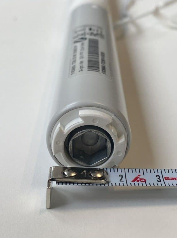
DWNTDBU25ZB
Jun 23, 2026TDBU 25 WF Zigbee HP 5183668
Equipment Class
DTS - Digital Transmission System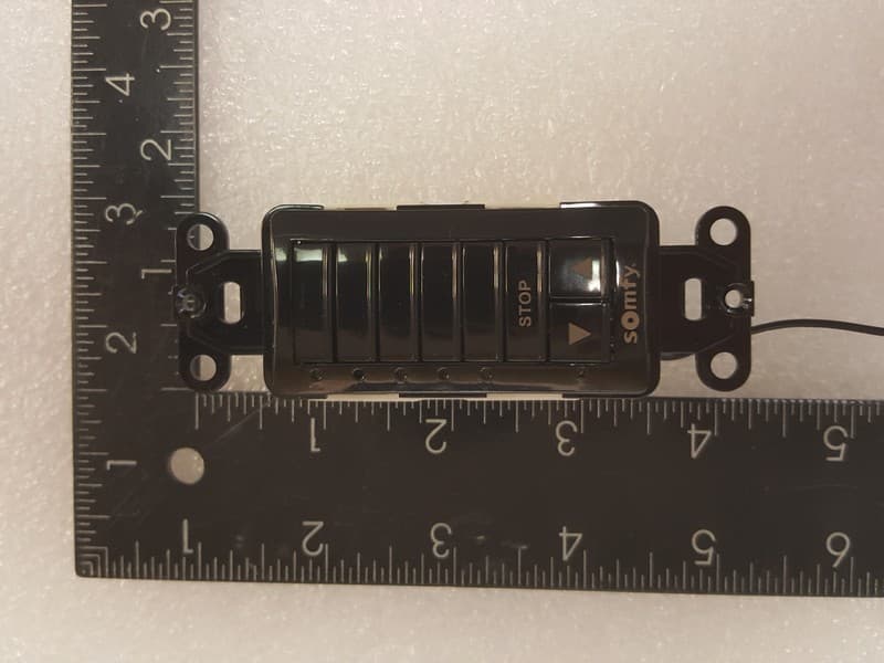
DWNDECOFLEX2
Feb 25, 2026Decoflex RTS In-Wall Mount 1810830
Equipment Class
DSC - Part 15 Security/Remote Control Transmitter
DWN-ROLLUPZB24
Sep 23, 2025ROLL UP2 24 Zigbee HP LI-ON 5178669
Equipment Class
DTS - Digital Transmission System