DWNX10RTSX10 to RTS Interface 6300110
Somfy Systems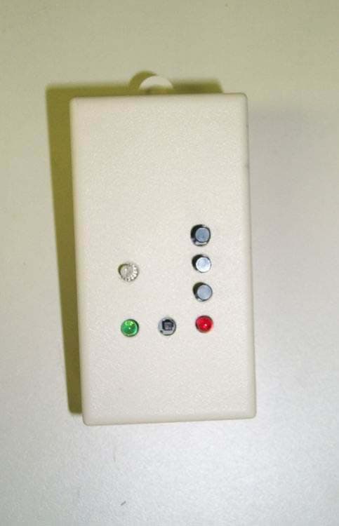
Click to zoom
Application Details
- Equipment Class
- DSC - Part 15 Security/Remote Control Transmitter
- Date of Grant
- Jul 10, 2005
- Application Purpose
- Original Equipment
- Date of Application
- Jul 10, 2005
- Equipment Note
- X10 to RTS Interface 6300110
- Frequency Range
- 433.42000000 - 433.42000000
- Company
- Somfy Systems
- Country
- United States
Documents & Files
Document Text
Text extracted from the exhibit documents filed with the FCC. Open a document above to read the original.
Users Manual
X10 to RTS Interface (6300110) Description The X10 to RTS interface is a 16-channel RTS transmitter that enables 3 rd party X10 systems to directly control Somfy’s line of RTS motors and controls using standard X10 commands. The interface also includes an RS232 input for direct control of RTS product from an RS232 port. The interface plugs into a standard 115 VAC electrical outlet. The interface has a range of 65’ in open air. Programming Instructions 1. Plug the interface into a standard electrical outlet. The green power LED illuminates. 2. Using the 16-position rotary dial, choose the channel you wish to bind to the RTS product. The RTS product must be in programming mode (refer to RTS product instructions). Depress the interface program button. The interface reverts to operating mode. 3. Repeat step 2 until all products are programmed. 4. To unbind a channel repeat step 2 for a previously programmed channel. 5. Using the 16-position rotary switch, choose the proper house code. X10 Operation The X10 commands used are BRIGHT for UP, DIM for DOWN and OFF for STOP. For example: 1 BRIGHT would send RTS signal 1 UP. RS232 Operation 9600 baud, no Parity, 1 stop bit, 7 data bits ASCII Protocol: <!><2 digit unit code><Command(U,S,D)> Somfy Systems, Inc. 47 Commerce Place, Cranbury , New Jersey 08512
Cover Letter(s)
1 Helen Zhao Subject:FW: FW: Somfy Systems,Inc., FCC ID: DWNX10RTS, Assessment NO.: AN05T4929, Notice#1 FCC-Rpt-X10-filing. pdf confidential letter.pdf POA-somfy.pdf From: weili Sent: Friday, July 08, 2005 8:41 PM To: Helen Zhao Subject: Re: FW: Somfy Systems,Inc., FCC ID: DWNX10RTS, Assessment NO.: AN05T4929, Notice#1 Hi, Helen. Attached please find the revised report and POA/ confidential letters. Regards, Wei > Question #1: Please revise the test report to indicate the rule part the EUT was tested with. > > Question #2: Please reorganize the LC test data to show frequency, Line (Hot line or Neotral line), reading, limit, margin. > > Question #3: Please submit an Agent Authorization Letter. > > Best Regards, > Helen Zhao > > > The items indicated above must be submitted before processing can continue > on the above referenced application. Failure to provide the requested > information within 30 days of the original e-mail date may result in > application dismissal and forfeiture of the filing fee. Also, please note > that partial responses increase processing time and should not be > submitted. Any questions about the content of this correspondence should > be directed to the e-mail address listed below the name of the sender. > >
External Photos
FCC ID: DWNX10RTS ——————————————————————————————————————————————— Advanced Compliance Lab, 6 Randolph Way, Hillsborough, NJ 08844 Tel: (908) 927-9288 Fax: (908) 927-0728 21 Front View FCC ID: DWNX10RTS ——————————————————————————————————————————————— Advanced Compliance Lab, 6 Randolph Way, Hillsborough, NJ 08844 Tel: (908) 927-9288 Fax: (908) 927-0728 22 Rear View
ID Label/Location Info
FCC ID: DWNX10RTS ——————————————————————————————————————————————— Advanced Compliance Lab, 6 Randolph Way, Hillsborough, NJ 08844 Tel: (908) 927-9288 Fax: (908) 927-0728 8 2. PRODUCT LABELING Figure 2.1 FCC ID Label Figure 2.2 Location of Label on the Side of EUT Figure 2.2 FCC ID Label Location FCC ID: DWNX10RTS This device complies with part 15 of the FCC Rules. Operating is subject to the following two conditions: (1) This device may not cause harmful interference, and (2) this device must accept any interference received, including interference that may cause undesired operation. Figure 2.1 FCC ID Label FCC Label
Internal Photos
FCC ID: DWNX10RTS ——————————————————————————————————————————————— Advanced Compliance Lab, 6 Randolph Way, Hillsborough, NJ 08844 Tel: (908) 927-9288 Fax: (908) 927-0728 23 Open View FCC ID: DWNX10RTS ——————————————————————————————————————————————— Advanced Compliance Lab, 6 Randolph Way, Hillsborough, NJ 08844 Tel: (908) 927-9288 Fax: (908) 927-0728 24 Component Side FCC ID: DWNX10RTS ——————————————————————————————————————————————— Advanced Compliance Lab, 6 Randolph Way, Hillsborough, NJ 08844 Tel: (908) 927-9288 Fax: (908) 927-0728 25 Foil Side FCC ID: DWNX10RTS ——————————————————————————————————————————————— Advanced Compliance Lab, 6 Randolph Way, Hillsborough, NJ 08844 Tel: (908) 927-9288 Fax: (908) 927-0728 26 Component Side/PCB1 FCC ID: DWNX10RTS ——————————————————————————————————————————————— Advanced Compliance Lab, 6 Randolph Way, Hillsborough, NJ 08844 Tel: (908) 927-9288 Fax: (908) 927-0728 27 Foil Side/PCB1
Operational Description
June 14, 2005 OPERATIONAL DESCRIPTION SOMFY X10 TO RTS CONVERTER Introduction This module receives power line carrier signals in a standard format known as X10 and up on receipt of certain such commands sends predetermined commands through a radio transmitter operating at 433.42 MHz to devices manufactured by Somfy. The module derives it power supply from the normal 120 Volt AC power line through a step down transformer. The X10 signals are capacitively coupled from the power line. A rotary switch on the module allows the user to have the module respond to one of 16 codes. Push buttons on the module allow manually sending radio commands to the target device. Technical Specifications Transmitter frequency- 433.42 MHz Transmitter stabilization- SAW (tolerance +/- 200 kHz including temperature effects) Modulation- ASK (on-off) Data rate- Approximately 1200 baud Transmission time approximately 0.13 seconds Microcomputer clock rate- 4.00 MHz (this is the only clock) Microcomputer clock reference- Quartz crystal Power source- 120 VAC power line. Draws approximately 50 mA. There is a 3V regulator for all circuits Circuit Description Power for the system is provided by a small UL approved step down transformer to about 5 Volts AC with a rectifier to provide about 6VDC. A linear voltage regulator reduces the voltage to a stabilized 3.0 volts for all of the circuits including the microcontroller and the transmitter. The transmitter oscillator is a standard Colpitts configuration using a SAW resonator to set the transmitter frequency. The ASK (on-off) modulation is carried out by turning the transmitter and amplifier one and off following the bit pattern. The control of the transmitter is directly from a port pin on the microcontroller. The oscillator operates at a nominal frequency of 433.42 MHz. The output of the oscillator is coupled to an amplifier stage that increases the power to the needed level and isolates the oscillator from antenna loading effects. The output of the amplifier goes to the antenna through a PI filter to reduce spurious signals. The microcomputer operates from a 4.00 MHz crystal. The microcomputer instruction rate is about 1 MHz (1/4 of the clock rate). The microcomputer runs at this clock rate all of the time. The detection of the X10 signals is synchronized to the 60 Hz power line. All other timings are based on software timing from the instruction sequences. There are no other timing elements. The microcomputer controls the transmit functions and the data conversion. An EEPROM memory stores the unique serial number for each module. The transmitter is activated based on receipt of the designated X10 power line carrier commands or based on manual activation of the push button switches on the module
Test Report
ELECTROMAGNETIC EMISSION COMPLIANCE REPORT of X-10 TO RTS INTERFACE MODEL: 6300110 FCC ID: DWNX10RTS July 1, 2005 This report concerns (check one): Original grant x Class II change Equipment type: Low Power Intentional Radiator Deferred grant requested per 47 CF 0.457(d)(1)(ii)? yes no x If yes, defer until: (date) Company agrees to notify the Commission by (date) of the intended date of announcement of the product so that the grant can be issued on that date. Transition Rules Request per 15.37? yes no x If no, assumed Part 15, Subpart B for unintentional radiators - the new 47 CFR [10-1-90 Edition] provision. Report prepared for: Somfy System, Inc. Report prepared by: Advanced Compliance Lab Report number: 0048-050620-01 The test result in this report IS supported and covered by the NVLAP accreditation 6 Randolph Way Hillsborough, NJ 08844 Tel: (908) 927 9288 Fax: (908) 927 0728 Advanced Compliance Laboratory FCC ID: DWNX10RTS ——————————————————————————————————————————————— Advanced Compliance Lab, 6 Randolph Way, Hillsborough, NJ 08844 Tel: (908) 927-9288 Fax: (908) 927-0728 2 Table of Contents Report Cover Page .........................................................................................................1 Table of Contents ...........................................................................................................2 Figures.............................................................................................................................3 1. GENERAL INFORMATION ...................................................................................4 1.1 Verification of Compliance .........................................................................4 1.2 Equipment Modifications............................................................................5 1.3 Product Information....................................................................................6 1.4 Test Methodology.........................................................................................6 1.5 Test Facility ..................................................................................................6 1.6 Test Equipment ............................................................................................6 1.7 Statement of the Document Use..................................................................7 2. PRODUCT LABELING............................................................................................8 3. SYSTEM TEST CONFIGURATION ......................................................................9 3.1 Justification ..................................................................................................9 3.2 Special Accessories.......................................................................................9 3.3 Configuration of Tested System .................................................................9 4. SYSTEM SCHEMATICS .........................................................................................13 5. CONDUCTED EMISSION DATA ..........................................................................14 5.1 Test Methods and Conditions .....................................................................14 5.2 Test Data .......................................................................................................14 6. RADIATED EMISSION DATA ...............................................................................17 6.1 Field Strength Calculation ..........................................................................17 6.2 Test Methods and Conditions .....................................................................17 6.2 Test Data .......................................................................................................17 6.4. Occupied Bandwidth ..................................................................................19 7. PHOTOS OF TESTED EUT ....................................................................................20 FCC ID: DWNX10RTS ——————————————————————————————————————————————— Advanced Compliance Lab, 6 Randolph Way, Hillsborough, NJ 08844 Tel: (908) 927-9288 Fax: (908) 927-0728 3 Figures Figure 2.1 FCC ID Label...............................................................................................8 Figure 2.2 Location of Label on Back of the EUT ......................................................8 Figure 3.1 Radiated Test Setup, Position 1..................................................................10 Figure 3.2 Radiated Test Setup, Position 2..................................................................10 Figure 3.3 Radiated Test Setup, Position 3..................................................................11 Figure 3.4 Conducted Test Setup, Front......................................................................12 Figure 3.5 Conducted Test Setup, Rear .......................................................................12 Figure 4.1 EUT Schematics ...........................................................................................13 Figure 5.1 Line Conducted............................................................................................15 Figure 5.2 Neutral Conducted .....................................................................................16 Figure 6.1 Bandwidth Plot ............................................................................................19 Figure 7.1 Front View....................................................................................................21 Figure 7.2 Rear View .....................................................................................................22 Figure 7.3 Inside View, Cover Opened ........................................................................23 Figure 7.4 Component Side ...........................................................................................24 Figure 7.5 Foil Side ..........................................…
Text truncated - open the document above for the full version.
Test Setup Photos
FCC ID: DWNX10RTS ——————————————————————————————————————————————— Advanced Compliance Lab, 6 Randolph Way, Hillsborough, NJ 08844 Tel: (908) 927-9288 Fax: (908) 927-0728 10 Figure 3.1 Radiated Test Setup, position 1-X Figure 3.2 Radiated Test Setup, position 2-Y FCC ID: DWNX10RTS ——————————————————————————————————————————————— Advanced Compliance Lab, 6 Randolph Way, Hillsborough, NJ 08844 Tel: (908) 927-9288 Fax: (908) 927-0728 11 Figure 3.3 Radiated Test Setup, position 3-Z FCC ID: DWNX10RTS ——————————————————————————————————————————————— Advanced Compliance Lab, 6 Randolph Way, Hillsborough, NJ 08844 Tel: (908) 927-9288 Fax: (908) 927-0728 12 Figure 3.4 Conducted Setup- Front Figure 3.5 Conducted Setup- Rear
Contact Information
Applicant
James P Hellander(Industrial Operations Manager)
Test Firm
Advanced Compliance LaboratoryWei Li
Technical Specifications
| # | Rule Parts | Frequency Range | Power Output |
|---|---|---|---|
| 1 | 15.231 | 433.42 MHz - 433.42 MHz | - |
Other Applications from Somfy Systems
DWNV2TDBUBL
Aug 19, 2026Ysia 1, Ysia 5, Ysia 5 TDBU HP Zigbee II, 5175210B, 5175211B, 5175066B
Equipment Class
DTS - Digital Transmission System
DWNVARBL
Aug 18, 2026Ysia 5 Variation HP Zigbee II, 5171079B
Equipment Class
DTS - Digital Transmission System
DWNTDBU25ZB
Jun 23, 2026TDBU 25 WF Zigbee HP 5183668
Equipment Class
DTS - Digital Transmission System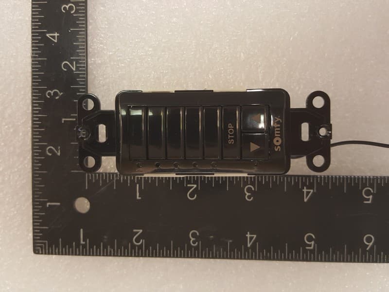
DWNDECOFLEX2
Feb 25, 2026Decoflex RTS In-Wall Mount 1810830
Equipment Class
DSC - Part 15 Security/Remote Control Transmitter
DWN-ROLLUPZB24
Sep 23, 2025ROLL UP2 24 Zigbee HP LI-ON 5178669
Equipment Class
DTS - Digital Transmission System