DWNZRTSIZwave to RTS Interface (ZRTSI) Model #1870202
Somfy Systems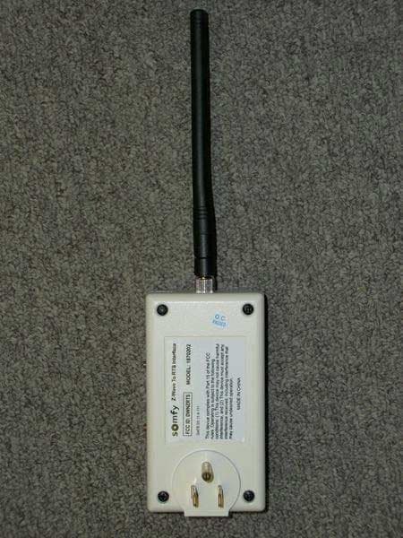
Click to zoom
Application Details
- Equipment Class
- DXT - Part 15 Low Power Transceiver, Rx Verified
- Date of Grant
- Jun 21, 2011
- Application Purpose
- Original Equipment
- Date of Application
- Jun 21, 2011
- Equipment Note
- Zwave to RTS Interface (ZRTSI) Model #1870202
- Frequency Range
- 908.42000000 - 908.42000000
- Company
- Somfy Systems
- Country
- United States
Documents & Files
Document Text
Text extracted from the exhibit documents filed with the FCC. Open a document above to read the original.
Users Manual
Page 1 of 5 Z-Wave RTS Interface Preliminary Instructions (ZRTSI) Somfy Part # 1870202 Product Overview The Somfy Z-Wave Universal RTS Interface (“ZRTSI”) is a Z-Wave bridge controller that resides as a secondary controller (only) node within a designated Z-Wave control network. It receives Z-Wave transmissions and coverts them to motor control commands for Somfy’s full range of RTS wireless controlled motors. It is recommended that one interface be used for each RTS motor area within a 25-35 foot radius of the interface. The ZRTSI has sixteen (16) virtual Z-Wave nodes that correspond to sixteen (16) RTS channels. All nodes can be automatically included with a Somfy TaHoma primary controller #1811151 (or other Z-Wave SIS controllers). Individual nodes can also be manually included in the network with TaHoma or other standard Z-Wave controllers. RTS channels are linked to Somfy RTS embedded motors per the RTS programming instructions for each RTS motor type. The ZRTSI is powered when plugged into an active receptacle. Z-Wave Certification ♦ This device is Z-Wave certified pending and can be controlled by all Z-Wave certified controllers. Page 2 of 5 Z- LED Z-BUTTON Rotary Selector S-LED S-BUTTON ZRTSI Installation and Operating Instructions Programming and operation buttons and indicators are found on the side of the ZRTSI as illustrated. The ZRTSI must be plugged into an AC power outlet within Z-Wave and RTS transmission ranges for programming and operation. Buttons & Indicators S-BUTTON - The S-BUTTON has 4 primary purposes: 1. Used for binding RTS Channels to Somfy RTS motors. 2. Used for manually including or excluding the ZRTSI into or out-of a Zwave network. 3. Used for verifying RTS communication between the ZRTSI and an RTS motor. Repeatedly pressing and releasing the S-BUTTON while in Normal Mode (see Mode Descriptions) will drive an RTS motor UP-STOP-DOWN etc. 4. Used for accessing inclusion mode or exclusion mode when pressed & held during power-up (see Mode Descriptions). S-LED - The S-LED changes 3 different colors: 1. Green – indicates normal mode of operation. 2. Red – flashing red indicates that an RTS transmission is occurring. 3. Yellow - Solid yellow indicates that a manual node inclusion is permitted. Flashing yellow indicates that manual node exclusion is permitted. ROTARY SELECTOR – The Rotary Selector is used to select individual virtual Z-Wave nodes or individual RTS channels. There are sixteen (16) total node/channels; Channels 1-9, Channel 10 = A, Channel 11 = B, Channel 12 = C, Channel 13 = D, Channel 14 = E, Channel 15 = F, Channel 16 = 0. Page 3 of 5 Z-BUTTON – The Z-BUTTON has 3 primary purposes: 1. Used for manually including the ZRTSI main node to a Zwave network. 2. Used for automatically including (with a SIS controller) all virtual nodes to a ZWave network. 3. Used for resetting the ZRTSI Z-Wave chip to factory defaults when pressed & held together with the S-BUTTON upon power-up (see Mode Descriptions). Z-LED - The Z-LED will be on during power-up of the ZRTSI. If the ZRTSI is included in a network, the LED will remain on. If the ZRTSI is not included in a network, the LED will turn off after 5 seconds. The Z-LED will also flash during automatic inclusion of the virtual nodes. Mode Descriptions Normal Mode - (also known as Green Mode) – Inserting the ZRTSI into an AC outlet will turn the S-LED green and enable Normal Mode. This means the ZRTSI is prepared for normal operation or programming. Normal Mode can also be enabled from Zwave Include or Exclude Modes (see Programming). Factory Default Mode – With the ZRTSI removed from the AC outlet, press & hold the Z-BUTTON. While holding the button, insert the ZRTSI into the AC outlet. Continue holding the Z-BUTTON while the Zwave chip and PIC variables are reset (approximately 10 seconds). The LEDs will flash during this time, and when reset is complete the S-LED will be GREEN and the Z-LED will be off. Please note that Factory Default does not reset any RTS programming. Z-Wave Node Include Mode - (also known as Solid Yellow Mode) – With the ZRTSI removed from the AC outlet, press & hold the the S-BUTTON. While holding the button, insert the ZRTSI into the AC outlet. Continue holding the S-BUTTON while Include Mode is being initiated. The S-LED will flash for approximately 6 seconds during this time, and Include Mode will be enabled when the S-LED is solid yellow. Release the S-BUTTON after the S-LED turns solid yellow. Z-Wave Node Exclusion Mode - (also known as Flashing Yellow Mode) – With the Zwave Include Mode enabled (see above), press & hold the S-Button for approximately 3 seconds until the S-LED begins to flash yellow. Release the S-BUTTON while the S-LED is flashing yellow. Factory Default / Include Mode – The ZRTSI can be reset to Factory Default and Node Include Mode in one step if desired. With the ZRTSI removed from the AC outlet, press & hold the Z -BUTTON and S-BUTTON together . While holding the buttons, insert the ZRTSI into the AC outlet. Continue holding both buttons while the Zwave chip is reset and Include Mode is enabled - this may take about 17 seconds. When the S-LED turns solid yellow, release the buttons. PROGRAMMING Add ZRTSI Base Node & ALL 16 Virtual Nodes to a Primary Z-Wave (SIS) Controller Automatically 1. Verify that the ZRTSI is not included in a Zwave network. 2. Enable the “Listening Mode” on the SIS controller. 3. Enable the Zwave Node Include Mode on the ZRTSI. 4. Press & hold the Z-BUTTON until the Z-LED begins to flash (approximately 3 seconds). The Base Node and 16 Virtual Nodes will be added to the SIS controller. This process may take several minutes, and the Z-LED will flash rapidly from time to time. The process is complete when the Z-LED stays solid red for 15 seconds or until all 16 virtual nodes appear with your SIS controller. Page 4 of 5 Add ZRTSI Base Node (Bridge Controller) Only 1. Verify that the ZRTSI is not included in a Zwave network. 2. Enable the “Li…
Text truncated - open the document above for the full version.
External Photos
FCC ID: DWNZRTSI ——————————————————————————————————————————————— Advanced Compliance Lab, 6 Randolph Way, Hillsborough, NJ 08844 Tel: (908) 927-9288 Fax: (908) 927- 0728 24 7.1 Top View FCC ID: DWNZRTSI ——————————————————————————————————————————————— Advanced Compliance Lab, 6 Randolph Way, Hillsborough, NJ 08844 Tel: (908) 927-9288 Fax: (908) 927- 0728 25 7.2 Back View
ID Label/Location Info
FCC ID: DWNZRTSI ——————————————————————————————————————————————— Advanced Compliance Lab, 6 Randolph Way, Hillsborough, NJ 08844 Tel: (908) 927-9288 Fax: (908) 927- 0728 8 2. PRODUCT LABELING Figure 2.1 FCC ID Label Figure 2.2 Location of Label on the Side of EUT Figure 2.2 FCC Label Location FCC ID: DWNZRTSI This device complies with part 15 of the FCC Rules. Operating is subject to the following two conditions: (1) This device may not cause harmful interference, and (2) this device must accept any interference received, including interference that may cause undesired operation. Figure 2.1 FCC ID Label (Only FCC ID shown on EUT) FCC Label
Internal Photos
FCC ID: DWNZRTSI ——————————————————————————————————————————————— Advanced Compliance Lab, 6 Randolph Way, Hillsborough, NJ 08844 Tel: (908) 927-9288 Fax: (908) 927- 0728 26 7.3 Cover Open Inside View FCC ID: DWNZRTSI ——————————————————————————————————————————————— Advanced Compliance Lab, 6 Randolph Way, Hillsborough, NJ 08844 Tel: (908) 927-9288 Fax: (908) 927- 0728 27 7.4 PCB Component View FCC ID: DWNZRTSI ——————————————————————————————————————————————— Advanced Compliance Lab, 6 Randolph Way, Hillsborough, NJ 08844 Tel: (908) 927-9288 Fax: (908) 927- 0728 28 7.5 PCB Foil View
Test Report
ELECTROMAGNETIC EMISSION COMPLIANCE REPORT of Z-WAVE TO RTS INTERFACE MODEL: 1870202 FCC ID: DWNZRTSI MAY 11, 2011 This report concerns (check one): Original grant x Class II change Equipment type: Low Power Intentional Radiator Deferred grant requested per 47 CF 0.457(d)(1)(ii)? yes no x If yes, defer until: (date) Company agrees to notify the Commission by (date) of the intended date of announcement of the product so that the grant can be issued on that date. Transition Rules Request per 15.37? yes no x If no, assumed Part 15, Subpart B for unintentional radiators - the new 47 CFR [10-1-90 Edition] provision. Report prepared for: SOMFY SYSTEM, INC. Report prepared by: Advanced Compliance Lab Report number: 0048-110509-01 Lab Code: 200101 The test result in this report IS supported and covered by the NVLAP accreditation 6 Randolph Way Hillsborough, NJ 08844 Tel: (908) 927 9288 Fax: (908) 927 0728 Advanced Compliance Laboratory FCC ID: DWNZRTSI ——————————————————————————————————————————————— Advanced Compliance Lab, 6 Randolph Way, Hillsborough, NJ 08844 Tel: (908) 927-9288 Fax: (908) 927- 0728 2 Table of Contents Report Cover Page .................................................................................................... 1 Table of Contents ...................................................................................................... 2 Figures ....................................................................................................................... 3 1. GENERAL INFORMATION ............................................................................... 4 1.1 Verification of Compliance ...................................................................... 4 1.2 Equipment Modifications ........................................................................ 5 1.3 Product Information ................................................................................ 6 1.4 Test Methodology..................................................................................... 6 1.5 Test Facility .............................................................................................. 6 1.6 Test Equipment ........................................................................................ 6 1.7 Statement of the Document Use............................................................... 7 2. PRODUCT LABELING........................................................................................ 8 3. SYSTEM TEST CONFIGURATION................................................................... 9 3.1 Justification .............................................................................................. 9 3.2 Special Accessories ................................................................................... 9 3.3 Configuration of Tested System .............................................................. 9 4. SYSTEM SCHEMATICS ..................................................................................... 12 5. RADIATED EMISSION DATA........................................................................... 13 5.1 Field Strength Calculation....................................................................... 13 5.2 Test Methods and Conditions.................................................................. 13 5.3 Test Data .................................................................................................. 13 6. CONDUCTED EMISSION DATA....................................................................... 20 7. PHOTOS OF TESTED EUT................................................................................. 23 FCC ID: DWNZRTSI ——————————————————————————————————————————————— Advanced Compliance Lab, 6 Randolph Way, Hillsborough, NJ 08844 Tel: (908) 927-9288 Fax: (908) 927- 0728 3 Figures Figure 2.1 FCC ID Label........................................................................................... 8 Figure 2.2 Location of Label on Back of the EUT.................................................... 8 Figure 3.1 Radiated Test Setup................................................................................. 10 Figure 3.2 Conducted Test Setup.............................................................................. 11 Figure 4.1 EUT Schematics ....................................................................................... 12 Figure 7.1-7.5 EUT Photos ........................................................................................ 24+ FCC ID: DWNZRTSI ——————————————————————————————————————————————— Advanced Compliance Lab, 6 Randolph Way, Hillsborough, NJ 08844 Tel: (908) 927-9288 Fax: (908) 927- 0728 4 1. GENERAL INFORMATION 1.1 Verification of Compliance EUT: Z-WAVE TO RTS INTERFACE Model: 1870202 Applicant: SOMFY SYSTEM, INC. Test Type: FCC Part 15C CERTIFICATION 15.231 and 15.249 Result: PASS Tested by: ADVANCED COMPLIANCE LABORATORY Test Completion Date: MAY 11, 2011 Report Number: 0048-110509-01 The above equipment was tested by Compliance Laboratory, Advanced Technologies, Inc. for compliance with the requirement set forth in the FCC rules and regulations Part 15 subpart C. This said equipment in the configuration described in the report, shows the maximum emission levels emanating from equipment are within the compliance requirements. The estimated uncertainty of the test result is given as following. The method of uncertainty calculation is provided in Advanced Compliance Lab. Doc. No. 0048-01-01. Prob. Dist. Uncertainty(dB) Uncertainty(dB) Uncertainty(dB) 30-1000MHz 1-6.5GHz Conducted Combined Std. Uncertainty u c norm. ±2.36 ±2.99 ±1.83 ____________________ Wei Li Date: MAY 11, 2011 Lab Manager Advanced Compliance Lab FCC ID: DWNZRTSI ——————————————————————————————————————————————— Advanced Compliance Lab, 6 Randolph Way, Hillsborough, NJ 08844 Tel: (908) 927-9288 Fax: (908) 927- 0728 5 1.2 Equipment Modifications N/A FCC ID: DWNZRTSI ——————————————————————————————————————————————— Advanced Compli…
Text truncated - open the document above for the full version.
Test Setup Photos
FCC ID: DWNZRTSI ——————————————————————————————————————————————— Advanced Compliance Lab, 6 Randolph Way, Hillsborough, NJ 08844 Tel: (908) 927-9288 Fax: (908) 927- 0728 10 Figure 3.1 Radiated Test Setup FCC ID: DWNZRTSI ——————————————————————————————————————————————— Advanced Compliance Lab, 6 Randolph Way, Hillsborough, NJ 08844 Tel: (908) 927-9288 Fax: (908) 927- 0728 11 Figure 3.2 Conducted Test Setup
Contact Information
Applicant
James P Hellander(Industrial Operations Manager)
Test Firm
Advanced Compliance LaboratoryWei Li
Technical Specifications
| # | Rule Parts | Frequency Range | Power Output |
|---|---|---|---|
| 1 | 15C | 908.42 MHz - 908.42 MHz | - |
Other Applications from Somfy Systems
DWNV2TDBUBL
Aug 19, 2026Ysia 1, Ysia 5, Ysia 5 TDBU HP Zigbee II, 5175210B, 5175211B, 5175066B
Equipment Class
DTS - Digital Transmission System
DWNVARBL
Aug 18, 2026Ysia 5 Variation HP Zigbee II, 5171079B
Equipment Class
DTS - Digital Transmission System
DWNTDBU25ZB
Jun 23, 2026TDBU 25 WF Zigbee HP 5183668
Equipment Class
DTS - Digital Transmission System
DWNDECOFLEX2
Feb 25, 2026Decoflex RTS In-Wall Mount 1810830
Equipment Class
DSC - Part 15 Security/Remote Control Transmitter
DWN-ROLLUPZB24
Sep 23, 2025ROLL UP2 24 Zigbee HP LI-ON 5178669
Equipment Class
DTS - Digital Transmission System